Hardware Maintenance Manual
Page 1
ThinkCentre Hardware Maintenance Manual Machine Types: 7258, 7259, 7260, 7267, 7268, 7269, 7270, 7279, 7280, 7290, 7296, 7297, 7298, 7303, 7304, 7306, 7307, 7408, 7413, 7487, 7491, 7506, 7508, 7514, 7843, and 7847
ThinkCentre Hardware Maintenance Manual Machine Types: 7258, 7259, 7260, 7267, 7268, 7269, 7270, 7279, 7280, 7290, 7296, 7297, 7298, 7303, 7304, 7306, 7307, 7408, 7413, 7487, 7491, 7506, 7508, 7514, 7843, and 7847
Hardware Maintenance Manual
Page 3
ThinkCentre Hardware Maintenance Manual Machine Types: 7258, 7259, 7260, 7267, 7268, 7269, 7270, 7279, 7280, 7290, 7296, 7297, 7298, 7303, 7304, 7306, 7307, 7408, 7413, 7487, 7491, 7506, 7508, 7514, 7843, and 7847
ThinkCentre Hardware Maintenance Manual Machine Types: 7258, 7259, 7260, 7267, 7268, 7269, 7270, 7279, 7280, 7290, 7296, 7297, 7298, 7303, 7304, 7306, 7307, 7408, 7413, 7487, 7491, 7506, 7508, 7514, 7843, and 7847
Hardware Maintenance Manual
Page 5
... 39 Using passwords 39 Password considerations 39 Power-On Password 40 Privileged Access Password 40 Setting, changing, and deleting a password . 40 © Copyright Lenovo 2008, 2011 Enabling or disabling a device 40 Selecting a startup device 41 Selecting a temporary startup device . . . . 41 Selecting or changing the...7260, 7268, 7270, 7280, 7296, 7298, 7304, 7307,7413, 7491, and 7508 . . . 30 Types 7259, 7267, 7269, 7279, 7297, 7303, 7306, 7487, 7506, and 7514 30 Chapter 4. Symptom-to-FRU Index . 43 Hard disk drive boot error 43 Power Supply Problems 43 Diagnostic error codes...
... 39 Using passwords 39 Password considerations 39 Power-On Password 40 Privileged Access Password 40 Setting, changing, and deleting a password . 40 © Copyright Lenovo 2008, 2011 Enabling or disabling a device 40 Selecting a startup device 41 Selecting a temporary startup device . . . . 41 Selecting or changing the...7260, 7268, 7270, 7280, 7296, 7298, 7304, 7307,7413, 7491, and 7508 . . . 30 Types 7259, 7267, 7269, 7279, 7297, 7303, 7306, 7487, 7506, and 7514 30 Chapter 4. Symptom-to-FRU Index . 43 Hard disk drive boot error 43 Power Supply Problems 43 Diagnostic error codes...
Hardware Maintenance Manual
Page 6
...update failure . . 522 Power management 523 Automatic configuration and power interface (ACPI) BIOS 523 Automatic Power-On features 523 Appendix A. 7303, 7306, 7408, 7487, 7506 and 7514 97 Locations 97 Rear connectors 97 Computer components 98 System board connectors 98 Opening the cover... an adapter card . . . . . 116 Completing the FRU replacement 118 Chapter 10. Notices 525 Television output notice 526 Trademarks 526 Index 527 iv ThinkCentre Hardware Maintenance Manual FRU lists 121 Overall: MT 7258, 7260, 7268, 7270, 7280, 7296, 7298, 7304, 7307,7413, 7491, and 7508 . ...
...update failure . . 522 Power management 523 Automatic configuration and power interface (ACPI) BIOS 523 Automatic Power-On features 523 Appendix A. 7303, 7306, 7408, 7487, 7506 and 7514 97 Locations 97 Rear connectors 97 Computer components 98 System board connectors 98 Opening the cover... an adapter card . . . . . 116 Completing the FRU replacement 118 Chapter 10. Notices 525 Television output notice 526 Trademarks 526 Index 527 iv ThinkCentre Hardware Maintenance Manual FRU lists 121 Overall: MT 7258, 7260, 7268, 7270, 7280, 7296, 7298, 7304, 7307,7413, 7491, and 7508 . ...
Hardware Maintenance Manual
Page 36
...) Height: 402 mm (15.8 inches) Depth: 440 mm (17.3 inches) Weight Maximum configuration as shipped: 11.2 kg (24.7 lbs) Types 7259, 7267, 7269, 7279, 7297, 7303, 7306, 7487, 7506, and 7514 This section lists the physical specifications. 30 ThinkCentre Hardware Maintenance Manual
...) Height: 402 mm (15.8 inches) Depth: 440 mm (17.3 inches) Weight Maximum configuration as shipped: 11.2 kg (24.7 lbs) Types 7259, 7267, 7269, 7279, 7297, 7303, 7306, 7487, 7506, and 7514 This section lists the physical specifications. 30 ThinkCentre Hardware Maintenance Manual
Hardware Maintenance Manual
Page 103
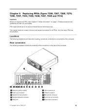
... connector 4 Standard keyboard connector 5 Serial port 8 USB connectors (4) 9 Ethernet connector 10 Microphone connector 11 Audio line-out connector 12 Audio line-in connector © Copyright Lenovo 2008, 2011 97 FRU replacements are documented. This chapter does not contain a remove and replace procedure for all FRUs. Replacing FRUs (Types 7259, 7267, 7269...
... connector 4 Standard keyboard connector 5 Serial port 8 USB connectors (4) 9 Ethernet connector 10 Microphone connector 11 Audio line-out connector 12 Audio line-in connector © Copyright Lenovo 2008, 2011 97 FRU replacements are documented. This chapter does not contain a remove and replace procedure for all FRUs. Replacing FRUs (Types 7259, 7267, 7269...
Hardware Maintenance Manual
Page 105
Replacing FRUs (Types 7259, 7267, 7269, 7279, 7290, 7297, 7303, 7306, 7408, 7487, 7506 and 7514) 99 Disconnect the cables attached to remove the cover. Chapter 9. Unplug all power cords from the drives, shut down ...
Replacing FRUs (Types 7259, 7267, 7269, 7279, 7290, 7297, 7303, 7306, 7408, 7487, 7506 and 7514) 99 Disconnect the cables attached to remove the cover. Chapter 9. Unplug all power cords from the drives, shut down ...
Hardware Maintenance Manual
Page 107
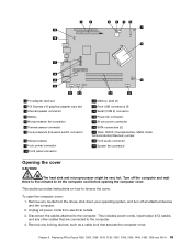
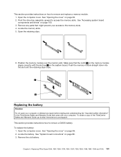
...Open the retaining clips. 6. Position the memory module over the memory slot. To obtain a copy of the ThinkCentre Safety and Warranty Guide, go to:http://www.lenovo.com/support This section provides instructions how to access the memory slots. Replacing the battery Attention Do not open... Open the computer cover. See "Opening the cover" on page 98. 3. Chapter 9. Replacing FRUs (Types 7259, 7267, 7269, 7279, 7290, 7297, 7303, 7306, 7408, 7487, 7506 and 7514) 101 Locate the battery. See "Accessing system board components and drives" on page 99. 2. Open the computer...
...Open the retaining clips. 6. Position the memory module over the memory slot. To obtain a copy of the ThinkCentre Safety and Warranty Guide, go to:http://www.lenovo.com/support This section provides instructions how to access the memory slots. Replacing the battery Attention Do not open... Open the computer cover. See "Opening the cover" on page 98. 3. Chapter 9. Replacing FRUs (Types 7259, 7267, 7269, 7279, 7290, 7297, 7303, 7306, 7408, 7487, 7506 and 7514) 101 Locate the battery. See "Accessing system board components and drives" on page 99. 2. Open the computer...
Hardware Maintenance Manual
Page 109
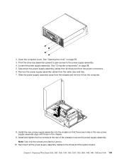
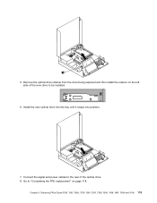
..." on page 99. 3. Remove the power supply assembly cables from the power connectors. 6. Replacing FRUs (Types 7259, 7267, 7269, 7279, 7290, 7297, 7303, 7306, 7408, 7487, 7506 and 7514) 103 Locate the power supply assembly. Install the new power supply assembly into the chassis so that the screw... holes in the new power supply assembly align with those in the chassis. 9. Note: Use only the screws provided by Lenovo. 10. Install and tighten the four screws at the rear of the chassis to the power supply assembly. 4. 2. Chapter 9. Open the computer ...
..." on page 99. 3. Remove the power supply assembly cables from the power connectors. 6. Replacing FRUs (Types 7259, 7267, 7269, 7279, 7290, 7297, 7303, 7306, 7408, 7487, 7506 and 7514) 103 Locate the power supply assembly. Install the new power supply assembly into the chassis so that the screw... holes in the new power supply assembly align with those in the chassis. 9. Note: Use only the screws provided by Lenovo. 10. Install and tighten the four screws at the rear of the chassis to the power supply assembly. 4. 2. Chapter 9. Open the computer ...

Hardware Maintenance Manual
Page 111
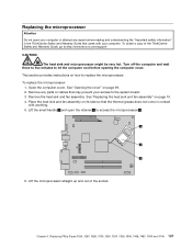
... microprocessor socket. The failing system board must be returned with the alignment keys 2 of the socket. c. Replacing FRUs (Types 7259, 7267, 7269, 7279, 7290, 7297, 7303, 7306, 7408, 7487, 7506 and 7514) 105 Grasp the microprocessor on the failing system board.
... microprocessor socket. The failing system board must be returned with the alignment keys 2 of the socket. c. Replacing FRUs (Types 7259, 7267, 7269, 7279, 7290, 7297, 7303, 7306, 7408, 7487, 7506 and 7514) 105 Grasp the microprocessor on the failing system board.
Hardware Maintenance Manual
Page 113
... fan assembly on page 74. 4. Replacing FRUs (Types 7259, 7267, 7269, 7279, 7290, 7297, 7303, 7306, 7408, 7487, 7506 and 7514) 107 To obtain a copy of the socket. This section provides ...fan assembly" on its side so that the thermal grease does not come in the ThinkCentre Safety and Warranty Guide that may prevent your computer. Turn off the computer and wait...any parts or cables that came with anything. 5. Lift the microprocessor straight up and out of the ThinkCentre Safety and Warranty Guide, go to access the microprocessor 2 . 6. To replace the microprocessor: 1. Open...
... fan assembly on page 74. 4. Replacing FRUs (Types 7259, 7267, 7269, 7279, 7290, 7297, 7303, 7306, 7408, 7487, 7506 and 7514) 107 To obtain a copy of the socket. This section provides ...fan assembly" on its side so that the thermal grease does not come in the ThinkCentre Safety and Warranty Guide that may prevent your computer. Turn off the computer and wait...any parts or cables that came with anything. 5. Lift the microprocessor straight up and out of the ThinkCentre Safety and Warranty Guide, go to access the microprocessor 2 . 6. To replace the microprocessor: 1. Open...
Hardware Maintenance Manual
Page 115
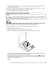
...fan assembly. See "Replacing the heat sink and fan assembly" on page 99. 2. To obtain a copy of the ThinkCentre Safety and Warranty Guide, go to the heat sink and fan assembly. 3. Open the computer cover. Pivot the drive ...bay assembly upward to gain access to :http://www.lenovo.com/support CAUTION: The heat sink and microprocessor might be very hot. Reinstall any other parts or reconnect any repair... and fan assembly: 1. Replacing FRUs (Types 7259, 7267, 7269, 7279, 7290, 7297, 7303, 7306, 7408, 7487, 7506 and 7514) 109
...fan assembly. See "Replacing the heat sink and fan assembly" on page 99. 2. To obtain a copy of the ThinkCentre Safety and Warranty Guide, go to the heat sink and fan assembly. 3. Open the computer cover. Pivot the drive ...bay assembly upward to gain access to :http://www.lenovo.com/support CAUTION: The heat sink and microprocessor might be very hot. Reinstall any other parts or reconnect any repair... and fan assembly: 1. Replacing FRUs (Types 7259, 7267, 7269, 7279, 7290, 7297, 7303, 7306, 7408, 7487, 7506 and 7514) 109

Hardware Maintenance Manual
Page 117
... install a new hard disk drive into position. 10. Chapter 9. Go to the new hard disk drive. 9. Replacing FRUs (Types 7259, 7267, 7269, 7279, 7290, 7297, 7303, 7306, 7408, 7487, 7506 and 7514) 111 Connect the signal cable and the power cable to "Completing the FRU replacement" on the bracket with the...
... install a new hard disk drive into position. 10. Chapter 9. Go to the new hard disk drive. 9. Replacing FRUs (Types 7259, 7267, 7269, 7279, 7290, 7297, 7303, 7306, 7408, 7487, 7506 and 7514) 111 Connect the signal cable and the power cable to "Completing the FRU replacement" on the bracket with the...
Hardware Maintenance Manual
Page 119
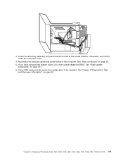
Install the new optical drive into the bay until it snaps into position. 7. Chapter 9. Go to "Completing the FRU replacement" on the left side of the new drive to the rear of the optical drive. 8. Replacing FRUs (Types 7259, 7267, 7269, 7279, 7290, 7297, 7303, 7306, 7408, 7487, 7506 and 7514) 113 5. Connect the signal and power cables to be installed. 6. Remove the optical drive retainer from the drive being replaced and then install the retainer on page 118.
Install the new optical drive into the bay until it snaps into position. 7. Chapter 9. Go to "Completing the FRU replacement" on the left side of the new drive to the rear of the optical drive. 8. Replacing FRUs (Types 7259, 7267, 7269, 7279, 7290, 7297, 7303, 7306, 7408, 7487, 7506 and 7514) 113 5. Connect the signal and power cables to be installed. 6. Remove the optical drive retainer from the drive being replaced and then install the retainer on page 118.
Hardware Maintenance Manual
Page 121
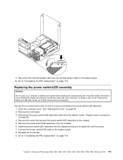
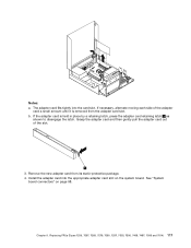
Go to "Completing the FRU replacement" on how to :http://www.lenovo.com/support This section provides instructions on page 118. To obtain a copy of the ThinkCentre Safety and Warranty Guide, go to remove and replace the power switch/LED assembly. 1. "System board connectors" on page 118. 9. ...the thermal sensor cable to the system board. 8. Remove the front bezel. 3. Replacing FRUs (Types 7259, 7267, 7269, 7279, 7290, 7297, 7303, 7306, 7408, 7487, 7506 and 7514) 115 Replacing the power switch/LED assembly Attention Do not open your computer. Remove the screw that came ...
Go to "Completing the FRU replacement" on how to :http://www.lenovo.com/support This section provides instructions on page 118. To obtain a copy of the ThinkCentre Safety and Warranty Guide, go to remove and replace the power switch/LED assembly. 1. "System board connectors" on page 118. 9. ...the thermal sensor cable to the system board. 8. Remove the front bezel. 3. Replacing FRUs (Types 7259, 7267, 7269, 7279, 7290, 7297, 7303, 7306, 7408, 7487, 7506 and 7514) 115 Replacing the power switch/LED assembly Attention Do not open your computer. Remove the screw that came ...
Hardware Maintenance Manual
Page 123
... adapter card from the adapter card slot. Install the adapter card into the card slot. Chapter 9. Replacing FRUs (Types 7259, 7267, 7269, 7279, 7290, 7297, 7303, 7306, 7408, 7487, 7506 and 7514) 117 If necessary, alternate moving each side of the slot. 3. b.
... adapter card from the adapter card slot. Install the adapter card into the card slot. Chapter 9. Replacing FRUs (Types 7259, 7267, 7269, 7279, 7290, 7297, 7303, 7306, 7408, 7487, 7506 and 7514) 117 If necessary, alternate moving each side of the slot. 3. b.
Hardware Maintenance Manual
Page 125
... the locked position. If you have replaced the system board, you cannot close the computer cover. 4. Replacing FRUs (Types 7259, 7267, 7269, 7279, 7290, 7297, 7303, 7306, 7408, 7487, 7506 and 7514) 119
... the locked position. If you have replaced the system board, you cannot close the computer cover. 4. Replacing FRUs (Types 7259, 7267, 7269, 7279, 7290, 7297, 7303, 7306, 7408, 7487, 7506 and 7514) 119
Hardware Maintenance Manual
Page 323
...; MT 7298: • MT 7304: • MT 7307: • MT 7491: • MT 7508: FRU # CRU 89Y1896 1 89Y1897 1 Overall: MT 7259, 7267, 7269, 7279, 7297, 7303, 7306, 7487, 7506, and 7514 The following replaceable components are available for the 7259, 7267, 7269, 7279, 7297...
...; MT 7298: • MT 7304: • MT 7307: • MT 7491: • MT 7508: FRU # CRU 89Y1896 1 89Y1897 1 Overall: MT 7259, 7267, 7269, 7279, 7297, 7303, 7306, 7487, 7506, and 7514 The following replaceable components are available for the 7259, 7267, 7269, 7279, 7297...
Hardware Maintenance Manual
Page 324
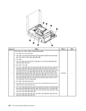
...: B2V B3J B5J B6J B7J B8J B9J A1J A3J A8U A8G A8M A8A A8H A8V A9U A9L B1U • MT 7297: A1V A2V • MT 7303: G2S G2P G2Y C4V G3A G3Q G3T G4A G4Q G4T G5A G5Q G5T A2M A2A A2Q A2T A2K E9A E9Q E9T F2M F2A F2Q F2T... 7514: A2U A2F A2S A2P A2L A2D A2Y A2G A2M A2A A2Q A2T A2C A2B A2H A2V A2K A2R A2E A2J FRU # 40Y9035 CRU 1 318 ThinkCentre Hardware Maintenance Manual
...: B2V B3J B5J B6J B7J B8J B9J A1J A3J A8U A8G A8M A8A A8H A8V A9U A9L B1U • MT 7297: A1V A2V • MT 7303: G2S G2P G2Y C4V G3A G3Q G3T G4A G4Q G4T G5A G5Q G5T A2M A2A A2Q A2T A2K E9A E9Q E9T F2M F2A F2Q F2T... 7514: A2U A2F A2S A2P A2L A2D A2Y A2G A2M A2A A2Q A2T A2C A2B A2H A2V A2K A2R A2E A2J FRU # 40Y9035 CRU 1 318 ThinkCentre Hardware Maintenance Manual
Hardware Maintenance Manual
Page 326
... C2F C3U C3F • MT 7269: • MT 7279: A4J A5J A6J • MT 7297: • MT 7303: BAU BAF BBU BBF BCU BCF G6M A3M A3A A4M A4A A4Q A4T A4K C3G B1G B2G B3G C1S C1Y C1M C1A C1Q...C4F • MT 7269: F3S F3D F3Y H1S H1D H1Y • MT 7279: E1G E2G A7J • MT 7297: • MT 7303: S2V S3V S4V S5V A5M A5K A6M A6K • MT 7306: • MT 7408: • MT 7506: A6G A7G •... C4F • MT 7269: F3S F3D F3Y H1S H1D H1Y • MT 7279: E1G E2G A7J • MT 7297: • MT 7303: S2V S3V S4V S5V A5M A5K A6M A6K • MT 7306: • MT 7408: • MT 7506: • MT 7514: ...
... C2F C3U C3F • MT 7269: • MT 7279: A4J A5J A6J • MT 7297: • MT 7303: BAU BAF BBU BBF BCU BCF G6M A3M A3A A4M A4A A4Q A4T A4K C3G B1G B2G B3G C1S C1Y C1M C1A C1Q...C4F • MT 7269: F3S F3D F3Y H1S H1D H1Y • MT 7279: E1G E2G A7J • MT 7297: • MT 7303: S2V S3V S4V S5V A5M A5K A6M A6K • MT 7306: • MT 7408: • MT 7506: A6G A7G •... C4F • MT 7269: F3S F3D F3Y H1S H1D H1Y • MT 7279: E1G E2G A7J • MT 7297: • MT 7303: S2V S3V S4V S5V A5M A5K A6M A6K • MT 7306: • MT 7408: • MT 7506: • MT 7514: ...