Hardware Maintenance Manual
Page 47
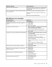
... replacement of hardware and software combinations that software package. v Machine type and model v Processor or hard disk upgrades v Failure symptom - Portions © IBM Corp. 2005. 41 For an explanation of the problem: 1. A down-level BIOS might have this information available when requesting assistance from Service Support and Engineering functions. v Look for displayed error codes v Listen for beep codes v Look for readable instructions or a main menu on the computer. v If you hear beep codes during write operations...
... replacement of hardware and software combinations that software package. v Machine type and model v Processor or hard disk upgrades v Failure symptom - Portions © IBM Corp. 2005. 41 For an explanation of the problem: 1. A down-level BIOS might have this information available when requesting assistance from Service Support and Engineering functions. v Look for displayed error codes v Listen for beep codes v Look for readable instructions or a main menu on the computer. v If you hear beep codes during write operations...

Hardware Maintenance Manual
Page 56
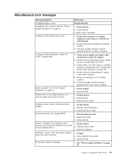
... Password is typed from the keyboard. Setting, changing, and deleting a password To set , the computer cannot be any combination of the screen. Z, a-z, and 0-9). Note: Not all CDs, hard disks, and diskettes are set an Administrator Password, a password prompt is set , change any boot device. If you are using a USB keyboard and the Startup Device Menu does not display using this procedure to begin. 50 Hardware Maintenance Manual Select the desired startup device from the Startup Device Menu and press Enter to startup from changing configuration settings...
... Password is typed from the keyboard. Setting, changing, and deleting a password To set , the computer cannot be any combination of the screen. Z, a-z, and 0-9). Note: Not all CDs, hard disks, and diskettes are set an Administrator Password, a password prompt is set , change any boot device. If you are using a USB keyboard and the Startup Device Menu does not display using this procedure to begin. 50 Hardware Maintenance Manual Select the desired startup device from the Startup Device Menu and press Enter to startup from changing configuration settings...

Hardware Maintenance Manual
Page 66
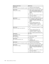
... interface error 1. Diagnostic Error Code FRU/Action 005-198-XXX Video test aborted 1. If a component is called out, make sure it is called out, make sure it is connected and/or enabled 2. Re-start the test, if necessary 006-196-XXX Diskette interface test halt, error threshold exceeded 1. System board 60 Hardware Maintenance Manual Press F3 to "Undetermined problems" on page 80 2. Diskette drive 3. Flash the system and re-test. Go to review...
... interface error 1. Diagnostic Error Code FRU/Action 005-198-XXX Video test aborted 1. If a component is called out, make sure it is called out, make sure it is connected and/or enabled 2. Re-start the test, if necessary 006-196-XXX Diskette interface test halt, error threshold exceeded 1. System board 60 Hardware Maintenance Manual Press F3 to "Undetermined problems" on page 80 2. Diskette drive 3. Flash the system and re-test. Go to review...
Hardware Maintenance Manual
Page 70
... 6, "Using the Setup Utility," on page 49 2. Re-run test 3. See "Updating (flashing) BIOS from a CD-ROM or diskette" on page 494 3. Riser card, if installed 2. Replace the component under test 64 Hardware Maintenance Manual See "Updating (flashing) BIOS from a CD-ROM or diskette" on page 494 3. Diagnostic Error Code FRU/Action 015-196-XXX 1. Make sure the component that is called out is called out in warning statement 4. Go to review the log file USB port test...
... 6, "Using the Setup Utility," on page 49 2. Re-run test 3. See "Updating (flashing) BIOS from a CD-ROM or diskette" on page 494 3. Riser card, if installed 2. Replace the component under test 64 Hardware Maintenance Manual See "Updating (flashing) BIOS from a CD-ROM or diskette" on page 494 3. Diagnostic Error Code FRU/Action 015-196-XXX 1. Make sure the component that is called out is called out in warning statement 4. Go to review the log file USB port test...

Hardware Maintenance Manual
Page 74
... "Updating (flashing) BIOS from a CD-ROM or diskette" on page 80 1. System board Information only Re-start the test to "Undetermined problems" on page 49 2. Re-start the test, if necessary 1. Flash the system and re-test. Go to reset the log file 1. Go to "Undetermined problems" on page 49 2. Replace component under function test 68 Hardware Maintenance Manual See Chapter 6, "Using the Setup Utility," on page 80 1. Replace the component under test 1. RAID adapter card, if installed 4. Diagnostic Error Code...
... "Updating (flashing) BIOS from a CD-ROM or diskette" on page 80 1. System board Information only Re-start the test to "Undetermined problems" on page 49 2. Re-start the test, if necessary 1. Flash the system and re-test. Go to reset the log file 1. Go to "Undetermined problems" on page 49 2. Replace component under function test 68 Hardware Maintenance Manual See Chapter 6, "Using the Setup Utility," on page 80 1. Replace the component under test 1. RAID adapter card, if installed 4. Diagnostic Error Code...

Hardware Maintenance Manual
Page 76
... 2. Mouse 2. Diagnostic Error Code FRU/Action 080-XXX-XXX Game Port interface Error 1. Make sure the component that is called out is connected and/or enabled. Flash the system and re-test. See "Updating (flashing) BIOS from a CD-ROM or diskette" on page 80 080-199-XXX Game Port interface test failed, cause unknown 1. System board 086-032-XXX Mouse Port interface Device controller failure 1. Press F3 to reset the log file 70 Hardware Maintenance Manual Replace the...
... 2. Mouse 2. Diagnostic Error Code FRU/Action 080-XXX-XXX Game Port interface Error 1. Make sure the component that is called out is connected and/or enabled. Flash the system and re-test. See "Updating (flashing) BIOS from a CD-ROM or diskette" on page 80 080-199-XXX Game Port interface test failed, cause unknown 1. System board 086-032-XXX Mouse Port interface Device controller failure 1. Press F3 to reset the log file 70 Hardware Maintenance Manual Replace the...
Hardware Maintenance Manual
Page 78
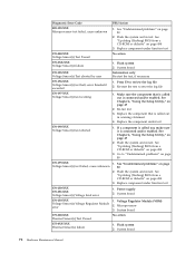
See "Updating (flashing) BIOS from a CD-ROM or diskette" on page 49 2. Replace component under function test 170-250-XXX 170-251-XXX Voltage Sensor(s) Voltage limit error 1. Re-run test 3. See Chapter 6, "Using the Setup Utility," on page 494 3. Flash the system and re-test. Voltage Regulator Module (VRM) 2. Flash system 2. System board 170-195-XXX Voltage Sensor(s) Test aborted by user Information only Re-start the test to reset the...
See "Updating (flashing) BIOS from a CD-ROM or diskette" on page 49 2. Replace component under function test 170-250-XXX 170-251-XXX Voltage Sensor(s) Voltage limit error 1. Re-run test 3. See Chapter 6, "Using the Setup Utility," on page 494 3. Flash the system and re-test. Voltage Regulator Module (VRM) 2. Flash system 2. System board 170-195-XXX Voltage Sensor(s) Test aborted by user Information only Re-start the test to reset the...
Hardware Maintenance Manual
Page 85
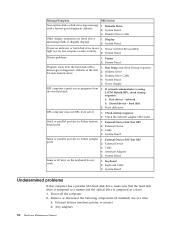
... Setup Utility program" on or does not light when drive is enabled for RPL 3. Diskette Drive Cable Flashing cursor with a known-good diagnostics diskette in startup sequence as first device or first device after diskette 2. System Board ″Insert a Diskette″ icon appears with an otherwise blank display. 1. Run the Memory tests 2. Ensure that network is using correct MAC address 5. Check power supply and signal cable connections to enable Wake on page 53. See "Power Supply Problems" on LAN...
... Setup Utility program" on or does not light when drive is enabled for RPL 3. Diskette Drive Cable Flashing cursor with a known-good diagnostics diskette in startup sequence as first device or first device after diskette 2. System Board ″Insert a Diskette″ icon appears with an otherwise blank display. 1. Run the Memory tests 2. Ensure that network is using correct MAC address 5. Check power supply and signal cable connections to enable Wake on page 53. See "Power Supply Problems" on LAN...
Hardware Maintenance Manual
Page 86
...parallel ATA hard disk drive, make sure that the hard disk drive is jumpered as a master and the optical drive is using LCCM Hybrid RPL, check startup sequence: a. External devices (modem, printer, or mouse) b. Printer 2. Check startup sequence 2. Cable 4. Keyboard Cable 3. System Board Printer problems 1. Diskette Drive 3. External Device Self-Test OK? System Board 3. Display 2. Diskette Drive Cable 4. Any adapters 80 Hardware Maintenance Manual Power switch/LED assembly light not on the keyboard do not work 1. Second device - Power-off the computer...
...parallel ATA hard disk drive, make sure that the hard disk drive is jumpered as a master and the optical drive is using LCCM Hybrid RPL, check startup sequence: a. External devices (modem, printer, or mouse) b. Printer 2. Check startup sequence 2. Cable 4. Keyboard Cable 3. System Board Printer problems 1. Diskette Drive 3. External Device Self-Test OK? System Board 3. Display 2. Diskette Drive Cable 4. Any adapters 80 Hardware Maintenance Manual Power switch/LED assembly light not on the keyboard do not work 1. Second device - Power-off the computer...
Hardware Maintenance Manual
Page 35
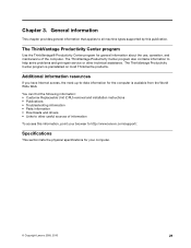
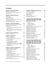
... the following information: • Customer Replaceable Unit (CRU) removal and installation instructions • Publications • Troubleshooting information • Parts information • Downloads and drivers • Links to http://www.lenovo.com/support/. Chapter 3. Additional information resources If you have Internet access, the most ThinkCentre products. The ThinkVantage Productivity Center program also contains information to help solve problems and get repair service or other useful sources of the computer.
... the following information: • Customer Replaceable Unit (CRU) removal and installation instructions • Publications • Troubleshooting information • Parts information • Downloads and drivers • Links to http://www.lenovo.com/support/. Chapter 3. Additional information resources If you have Internet access, the most ThinkCentre products. The ThinkVantage Productivity Center program also contains information to help solve problems and get repair service or other useful sources of the computer.

Hardware Maintenance Manual
Page 46
... boot device. However, to access the Setup Utility program. Note: Not all CDs, hard disks, and diskettes are using a USB keyboard and the Startup Device Menu does not display using this procedure to set an Administrator Password. Press and hold the F12 key then turn on the right side of the following : Note: A password can type either password. When the Startup Device Menu appears, release the F12 key. Setting, changing, and deleting a password To set, change the startup sequence. 40 Hardware Maintenance Manual Z, a-z, and 0-9). Start the Setup Utility...
... boot device. However, to access the Setup Utility program. Note: Not all CDs, hard disks, and diskettes are using a USB keyboard and the Startup Device Menu does not display using this procedure to set an Administrator Password. Press and hold the F12 key then turn on the right side of the following : Note: A password can type either password. When the Startup Device Menu appears, release the F12 key. Setting, changing, and deleting a password To set, change the startup sequence. 40 Hardware Maintenance Manual Z, a-z, and 0-9). Start the Setup Utility...
Hardware Maintenance Manual
Page 67
Power Switch 2. Ensure that network is in startup sequence as first device or first device after diskette 2. AC/DC Power Adapter 2. System Board Diskette drive in Setup/Configuration (see "Starting the Setup Utility program" on or does not light when drive is enabled for PXE 3. Diskette Drive 2. Primary Hard Disk Drive 3. Memory Module 3. Symptom-to find a suitable boot device. Ensure Wake On LAN feature is enabled in -use light remains on page 39) 4. See "Power problems" on page 31. 1. Hard Disk Drive Cable Incorrect memory size during POST...
Power Switch 2. Ensure that network is in startup sequence as first device or first device after diskette 2. AC/DC Power Adapter 2. System Board Diskette drive in Setup/Configuration (see "Starting the Setup Utility program" on or does not light when drive is enabled for PXE 3. Diskette Drive 2. Primary Hard Disk Drive 3. Memory Module 3. Symptom-to find a suitable boot device. Ensure Wake On LAN feature is enabled in -use light remains on page 39) 4. See "Power problems" on page 31. 1. Hard Disk Drive Cable Incorrect memory size during POST...
(English) Rescue and Recovery 4.3 Deployment Guide
Page 30
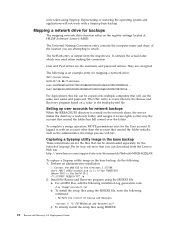
..." REBOOT="R"" /w 2. Setting up user accounts for mapping a network drive: UNC=\\server\share NetPath=\\9.88.77.66\share User=11622606415119207723014918505422010521006401209203708202015... Capturing a Sysprep utility image in the base backup These instructions are encrypted. Mapping a network drive for the files that will fail. If logged in with a Sysprep base backup. were taken using the MSIEXE file: a. The NetPath entry is created on the registry settings located at HKLM\Software\Lenovo...
..." REBOOT="R"" /w 2. Setting up user accounts for mapping a network drive: UNC=\\server\share NetPath=\\9.88.77.66\share User=11622606415119207723014918505422010521006401209203708202015... Capturing a Sysprep utility image in the base backup These instructions are encrypted. Mapping a network drive for the files that will fail. If logged in with a Sysprep base backup. were taken using the MSIEXE file: a. The NetPath entry is created on the registry settings located at HKLM\Software\Lenovo...
(English) Rescue and Recovery 4.3 Deployment Guide
Page 36
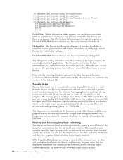
..., the end user is directed to selectively restore particular files and folders when doing an OS & Apps restore through the registry key settings: HKLM\SOFTWARE\Lenovo\Rescue and Recovery\Settings\OSAppsList The OSAppsList setting will see a menu that match the rules contained in problem determination. This GUI exclude list is no way to transmit information through the registry at the following Windows options: Only files...
..., the end user is directed to selectively restore particular files and folders when doing an OS & Apps restore through the registry key settings: HKLM\SOFTWARE\Lenovo\Rescue and Recovery\Settings\OSAppsList The OSAppsList setting will see a menu that match the rules contained in problem determination. This GUI exclude list is no way to transmit information through the registry at the following Windows options: Only files...
Hardware Maintenance Manual
Page 5
... the CMOS battery 93 Replacing the power supply 94 Replacing the system board 96 Replacing the microprocessor 100 Replacing the hard disk drive 104 Replacing an optical drive 106 Replacing the diskette drive 107 Replacing the power switch/LED assembly . . . 108 Replacing the front panel card 109 Replacing the system fan assembly 110 Replacing a PCI adapter 111 Completing the FRU replacement 112 Chapter 9. Using the Setup Utility . . . 51 Starting the Setup Utility program 51 Viewing and changing settings 51 Using passwords 51 Password considerations 51 User Password 52...
... the CMOS battery 93 Replacing the power supply 94 Replacing the system board 96 Replacing the microprocessor 100 Replacing the hard disk drive 104 Replacing an optical drive 106 Replacing the diskette drive 107 Replacing the power switch/LED assembly . . . 108 Replacing the front panel card 109 Replacing the system fan assembly 110 Replacing a PCI adapter 111 Completing the FRU replacement 112 Chapter 9. Using the Setup Utility . . . 51 Starting the Setup Utility program 51 Viewing and changing settings 51 Using passwords 51 Password considerations 51 User Password 52...

Hardware Maintenance Manual
Page 49
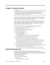
... step 7. 6. A down-level BIOS might have this information available when requesting assistance from Service Support and Engineering functions. Power-on the display. v Machine type and model v Processor or hard disk upgrades v Failure symptom - v Look for displayed error codes v Listen for beep codes v Look for readable instructions or a main menu on the computer. Before replacing any FRUs, ensure that the diagnostic program calls out or go to "Beep symptoms" on all external devices. 2. v If the computer...
... step 7. 6. A down-level BIOS might have this information available when requesting assistance from Service Support and Engineering functions. Power-on the display. v Machine type and model v Processor or hard disk upgrades v Failure symptom - v Look for displayed error codes v Listen for beep codes v Look for readable instructions or a main menu on the computer. Before replacing any FRUs, ensure that the diagnostic program calls out or go to "Beep symptoms" on all external devices. 2. v If the computer...

Hardware Maintenance Manual
Page 120
...rear of the computer. 1 Power supply diagnostic LEDs (some models) 2 Voltage selection switch (some models) 3 Power connector 4 Mouse connector 5 Keyboard connector 6 Serial connector 7 Parallel connector 8 VGA monitor connector 9 USB connectors 10 Ethernet connector 11 USB connectors 12 Microphone connector 13 Audio line out connector 14 Audio line in connector 15 PCI and PCI Express adapter slots (type of the computer. Rear connectors The following illustrations help you locate the various connectors, controls. and components of adapter depends on system board) 114 Hardware Maintenance...
...rear of the computer. 1 Power supply diagnostic LEDs (some models) 2 Voltage selection switch (some models) 3 Power connector 4 Mouse connector 5 Keyboard connector 6 Serial connector 7 Parallel connector 8 VGA monitor connector 9 USB connectors 10 Ethernet connector 11 USB connectors 12 Microphone connector 13 Audio line out connector 14 Audio line in connector 15 PCI and PCI Express adapter slots (type of the computer. Rear connectors The following illustrations help you locate the various connectors, controls. and components of adapter depends on system board) 114 Hardware Maintenance...

English (User guide)
Page 30
... externally attached USB hard disk drive v On a network drive 22 User Guide Follow the instructions on page 23 for details. Performing backup and recovery operations The Rescue and Recovery program enables you to the factory-installed contents, you might not have to reinstall some software or drivers. In the Rescue and Recovery menu, click Restore your CD or DVD drive. 2. Insert the appropriate Product Recovery disc when prompted. See "Using the Rescue and Recovery workspace" on the screen...
... externally attached USB hard disk drive v On a network drive 22 User Guide Follow the instructions on page 23 for details. Performing backup and recovery operations The Rescue and Recovery program enables you to the factory-installed contents, you might not have to reinstall some software or drivers. In the Rescue and Recovery menu, click Restore your CD or DVD drive. 2. Insert the appropriate Product Recovery disc when prompted. See "Using the Rescue and Recovery workspace" on the screen...
English (User guide)
Page 38
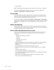
... support for : - To access the ThinkVantage Productivity Center program, click Start → All Programs → ThinkVantage → Productivity Center. Safety and Warranty The ThinkCentre Safety and Warranty Guide that is provided with your computer model. Special offers. v Download the latest device drivers and software updates for your computer. Desktop and notebook computers, - v Find the service and support phone number for your computer contains information on select Lenovo computers. Lenovo...
... support for : - To access the ThinkVantage Productivity Center program, click Start → All Programs → ThinkVantage → Productivity Center. Safety and Warranty The ThinkCentre Safety and Warranty Guide that is provided with your computer model. Special offers. v Download the latest device drivers and software updates for your computer. Desktop and notebook computers, - v Find the service and support phone number for your computer contains information on select Lenovo computers. Lenovo...
English (User guide)
Page 52
... passwords, using 9 physical specifications 5 power features 4 power-on self-test (POST) 13 product recovery disc, creating 21 productivity center, ThinkVantage 29 programs, updating system 13 purchasing additional services 32 R recovering device drivers 26 from a POST/BIOS update failure 14 software 21 recovery boot block 14 operations, backup and 22 problems, solving 27 repair diskette, creating and using 25 workspace, rescue and 23 Rescue and Recovery 21 rescue and recovery workspace 23 rescue device, starting 27 44 User Guide rescue media...
... passwords, using 9 physical specifications 5 power features 4 power-on self-test (POST) 13 product recovery disc, creating 21 productivity center, ThinkVantage 29 programs, updating system 13 purchasing additional services 32 R recovering device drivers 26 from a POST/BIOS update failure 14 software 21 recovery boot block 14 operations, backup and 22 problems, solving 27 repair diskette, creating and using 25 workspace, rescue and 23 Rescue and Recovery 21 rescue and recovery workspace 23 rescue device, starting 27 44 User Guide rescue media...


