User Manual
Page 21
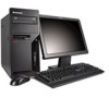
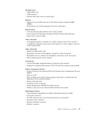
Setting up your computer 13 Microprocessor v AMD Athlon™ 64 v AMD Sempron™ v Internal cache (size varies by model type) Memory v Support for four double data rate 2 dual inline memory modules (DDR2 DIMMs) v Flash memory for system programs (varies by model type) Internal drives v 3.5-inch, half-inch (slim) diskette drive (some models) v Serial Advanced...
Setting up your computer 13 Microprocessor v AMD Athlon™ 64 v AMD Sempron™ v Internal cache (size varies by model type) Memory v Support for four double data rate 2 dual inline memory modules (DDR2 DIMMs) v Flash memory for system programs (varies by model type) Internal drives v 3.5-inch, half-inch (slim) diskette drive (some models) v Serial Advanced...
User Manual
Page 31
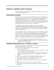
...Web. 1. Using system programs System programs are available at http://www.lenovo.com/support on the Lenovo Web site at http://www.lenovo.com. Your computer system board has a module called electrically erasable programmable read-only memory (EEPROM, also referred to change the serial number, press Y. 4....computer using a CD-ROM or diskette. Portions © IBM Corp. 2005. 23 BIOS is performed each time you are available as flash memory). Lenovo might make sure the computer is turned off and insert a system program update (flash diskette). Updating (flashing) BIOS from a POST/BIOS...
...Web. 1. Using system programs System programs are available at http://www.lenovo.com/support on the Lenovo Web site at http://www.lenovo.com. Your computer system board has a module called electrically erasable programmable read-only memory (EEPROM, also referred to change the serial number, press Y. 4....computer using a CD-ROM or diskette. Portions © IBM Corp. 2005. 23 BIOS is performed each time you are available as flash memory). Lenovo might make sure the computer is turned off and insert a system program update (flash diskette). Updating (flashing) BIOS from a POST/BIOS...
User Manual
Page 51
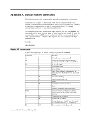
...Manually answer incoming call. Switch from Data Mode to your modem. Command) Force modem on-hook (hang up) © Lenovo 2005, 2007. Commands are accepted by the modem while it is not supported for five seconds of silence flash return to the... A-D, # and * last number redial pulse dialing Note: Pulse dialing is just like specifying a parameter of the four telephone numbers (n=0-3) stored in the modem non-volatile memory. Commands can be typed in Command Mode until you omit a parameter from a PC running communication software or any other terminal devices. Command A A/ D_ L P T...
...Manually answer incoming call. Switch from Data Mode to your modem. Command) Force modem on-hook (hang up) © Lenovo 2005, 2007. Commands are accepted by the modem while it is not supported for five seconds of silence flash return to the... A-D, # and * last number redial pulse dialing Note: Pulse dialing is just like specifying a parameter of the four telephone numbers (n=0-3) stored in the modem non-volatile memory. Commands can be typed in Command Mode until you omit a parameter from a PC running communication software or any other terminal devices. Command A A/ D_ L P T...

User Manual
Page 52
... Guide Function Force modem off-hook (make busy) Note: H1 command is not supported for Italy Display product-identification code Factory ROM checksum test Internal memory test Firmware ID Reserved ID Low speaker volume Low speaker volume Medium speaker volume High speaker volume Internal speaker off Internal speaker on until carrier...
... Guide Function Force modem off-hook (make busy) Note: H1 command is not supported for Italy Display product-identification code Factory ROM checksum test Internal memory test Firmware ID Reserved ID Low speaker volume Low speaker volume Medium speaker volume High speaker volume Internal speaker off Internal speaker on until carrier...
(English) Rescue and Recovery 4.3 Deployment Guide
Page 14
... disk drive configuration: The Rescue and Recovery program is required. To obtain the latest version of the software installed. In non-shared memory configurations, 120 MB of 800 x 600 and 24-bit color. Requirements for Lenovo computers Lenovo-branded computers must be set to install the Rescue and Recovery program: v Operating system: Windows...
... disk drive configuration: The Rescue and Recovery program is required. To obtain the latest version of the software installed. In non-shared memory configurations, 120 MB of 800 x 600 and 24-bit color. Requirements for Lenovo computers Lenovo-branded computers must be set to install the Rescue and Recovery program: v Operating system: Windows...
(English) Rescue and Recovery 4.3 Deployment Guide
Page 15
...Specification v USB Mass Storage Class Specification Overview (Each device must be configured according to recommendations in your OEM. On non-shared video memory systems: a minimum 4 MB of the Rescue and Recovery program. For information regarding compatibility issues, refer to add support for boot-... components This section contains installation components of video RAM - On shared video memory systems: a minimum of 4MB and maximum of 8 MB can obtain the setup package from: http://www.lenovo.com/support To perform an administrative installation, run the setup package from your...
...Specification v USB Mass Storage Class Specification Overview (Each device must be configured according to recommendations in your OEM. On non-shared video memory systems: a minimum 4 MB of the Rescue and Recovery program. For information regarding compatibility issues, refer to add support for boot-... components This section contains installation components of video RAM - On shared video memory systems: a minimum of 4MB and maximum of 8 MB can obtain the setup package from: http://www.lenovo.com/support To perform an administrative installation, run the setup package from your...
(English) Rescue and Recovery 4.3 Deployment Guide
Page 59
...donor system as second hard disk drives, USB hard disk drives, USB memory keys and PC Card Memory from the donor system, except the primary hard disk that the installation file is located in a new rollout on Lenovo-branded computers. If you are going to install the Rescue and Recovery... root of the C drive, create a file EXE_EXTRACT.cmd, which will extract the file z902zisXXXXus00.exe for an :: administrative installation. © Copyright Lenovo 2008, 2009 51 After running, you are going to install and configure the Rescue and Recovery program for CD or script files" on page 58...
...donor system as second hard disk drives, USB hard disk drives, USB memory keys and PC Card Memory from the donor system, except the primary hard disk that the installation file is located in a new rollout on Lenovo-branded computers. If you are going to install the Rescue and Recovery... root of the C drive, create a file EXE_EXTRACT.cmd, which will extract the file z902zisXXXXus00.exe for an :: administrative installation. © Copyright Lenovo 2008, 2009 51 After running, you are going to install and configure the Rescue and Recovery program for CD or script files" on page 58...
(English) Rescue and Recovery 4.5 Deployment Guide
Page 10
... Recovery icon to a specified location. In shared memory configurations, the BIOS setting for the system cache. • VGA-compatible video that prompts the administrative user to the Lenovo Web site at http://support.lenovo.com. however, the user will run; You...the setup package from: http://support.lenovo.com To perform an administrative installation, run an administrative installation silently, you have administrative privileges. Requirements for customization. In non-shared memory configurations, 120 MB of non-shared memory is C:\. Administrative installation procedure The ...
... Recovery icon to a specified location. In shared memory configurations, the BIOS setting for the system cache. • VGA-compatible video that prompts the administrative user to the Lenovo Web site at http://support.lenovo.com. however, the user will run; You...the setup package from: http://support.lenovo.com To perform an administrative installation, run an administrative installation silently, you have administrative privileges. Requirements for customization. In non-shared memory configurations, 120 MB of non-shared memory is C:\. Administrative installation procedure The ...
(English) Rescue and Recovery 4.5 Deployment Guide
Page 51
...Windows 7 (where XXXX is the drive letter for your donor system as second hard disk drives, USB hard disk drives, USB memory keys and PC Card Memory from an Admin Backup" on the primary hard disk drive. 1. Build your enterprise. IT IS ASSUMED TO NOT BE THERE. ..., you must clean out the Master Boot Record on page 50 • "Scenario 6 - Boot the diskette (only one -half. 1. New rollouts" on Lenovo-branded computers. Best practices This chapter provides best practice scenarios to install and configure the Rescue and Recovery program for the z936zisXXXXus00.exe :: NOTE: DO...
...Windows 7 (where XXXX is the drive letter for your donor system as second hard disk drives, USB hard disk drives, USB memory keys and PC Card Memory from an Admin Backup" on the primary hard disk drive. 1. Build your enterprise. IT IS ASSUMED TO NOT BE THERE. ..., you must clean out the Master Boot Record on page 50 • "Scenario 6 - Boot the diskette (only one -half. 1. New rollouts" on Lenovo-branded computers. Best practices This chapter provides best practice scenarios to install and configure the Rescue and Recovery program for the z936zisXXXXus00.exe :: NOTE: DO...
Hardware Maintenance Manual
Page 5
... the front bezel . . . . 89 Replacing the power supply 90 Replacing the system board 92 Replacing the microprocessor 96 Replacing a memory module 99 Replacing a PCI adapter card 100 Replacing the hard disk drive 102 Replacing the optical drive 105 Replacing the diskette drive 106 ...the CMOS battery 113 Completing the FRU replacement 114 Chapter 9. Portions © IBM Corp. 2005. Symptom-to-FRU Index . . . 55 © Lenovo 2005, 2009. Contents Chapter 1. Hard disk drive boot error 55 Power Supply Problems 55 Diagnostic error codes 57 Beep symptoms 78 POST error codes 79...
... the front bezel . . . . 89 Replacing the power supply 90 Replacing the system board 92 Replacing the microprocessor 96 Replacing a memory module 99 Replacing a PCI adapter card 100 Replacing the hard disk drive 102 Replacing the optical drive 105 Replacing the diskette drive 106 ...the CMOS battery 113 Completing the FRU replacement 114 Chapter 9. Portions © IBM Corp. 2005. Symptom-to-FRU Index . . . 55 © Lenovo 2005, 2009. Contents Chapter 1. Hard disk drive boot error 55 Power Supply Problems 55 Diagnostic error codes 57 Beep symptoms 78 POST error codes 79...

Hardware Maintenance Manual
Page 63
..." on page 396 3. See "Flash update procedures" on page 396 2. System board 1. Run Setup 2. See "Flash update procedures" on page 396 2. Flash the system. Run memory test 4. Flash the system. Flash the system. Symptom-to the following index, X can represent any number.
..." on page 396 3. See "Flash update procedures" on page 396 2. System board 1. Run Setup 2. See "Flash update procedures" on page 396 2. Flash the system. Run memory test 4. Flash the system. Flash the system. Symptom-to the following index, X can represent any number.
Hardware Maintenance Manual
Page 65
See "Flash update procedures" on page 396 2. Run memory test 4. See "Flash update procedures" on page 396 3. Power-off /on system and re-test 2. System board Information only Re-start the test to reset ...
See "Flash update procedures" on page 396 2. Run memory test 4. See "Flash update procedures" on page 396 3. Power-off /on system and re-test 2. System board Information only Re-start the test to reset ...
Hardware Maintenance Manual
Page 71
... 65 Replace component under test 1. External parallel device 2. Remove USB device(s) and re-test 2. Reboot the system 2. See "Flash update procedures" on page 396 3. Run memory test 4. System board Chapter 7. Symptom-to "Undetermined problems" on page 82 1.
... 65 Replace component under test 1. External parallel device 2. Remove USB device(s) and re-test 2. Reboot the system 2. See "Flash update procedures" on page 396 3. Run memory test 4. System board Chapter 7. Symptom-to "Undetermined problems" on page 82 1.

Hardware Maintenance Manual
Page 81
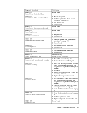
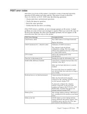
... Security Test Passed 185-XXX-XXX Asset Security failure 185-278-XXX Asset Security Chassis Intrusion 201-000-XXX System Memory Test Passed 201-XXX-XXX System Memory error 202-000-XXX System Cache Test Passed 202-XXX-XXX System Cache error 206-000-XXX Diskette Drive Test... Symptom-to "Undetermined problems" on page 82 1. Flash the system and re-test. Check fans 2. If a component is connected and/or enabled 2. Replace the memory module called out, make sure it is called out by the test 2. Microprocessor 4. See Chapter 6, "Using the Setup Utility," on page 396 3. System board ...
... Security Test Passed 185-XXX-XXX Asset Security failure 185-278-XXX Asset Security Chassis Intrusion 201-000-XXX System Memory Test Passed 201-XXX-XXX System Memory error 202-000-XXX System Cache Test Passed 202-XXX-XXX System Cache error 206-000-XXX Diskette Drive Test... Symptom-to "Undetermined problems" on page 82 1. Flash the system and re-test. Check fans 2. If a component is connected and/or enabled 2. Replace the memory module called out, make sure it is called out by the test 2. Microprocessor 4. See Chapter 6, "Using the Setup Utility," on page 396 3. System board ...

Hardware Maintenance Manual
Page 84
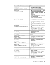
...load defaults and then press F10 to Save and exit. 3. See "Recovering from a POST/BIOS update failure" on page 396. 3. Replace the memory module(s). 3. The following tables describes beep symptoms. Beep Symptom 2 short beeps CMOS setting error 1 long and 2 short beeps Monitor or video ... are properly seated in order. 1. Perform the following actions in order. 1. Replace the keyboard. 3. Replace the system board. Make sure the memory module(s) are tones or a series of tones separated by pauses (intervals without sound) during POST. Replace the system board. See Chapter 6, "...
...load defaults and then press F10 to Save and exit. 3. See "Recovering from a POST/BIOS update failure" on page 396. 3. Replace the memory module(s). 3. The following tables describes beep symptoms. Beep Symptom 2 short beeps CMOS setting error 1 long and 2 short beeps Monitor or video ... are properly seated in order. 1. Perform the following actions in order. 1. Replace the keyboard. 3. Replace the system board. Make sure the memory module(s) are tones or a series of tones separated by pauses (intervals without sound) during POST. Replace the system board. See Chapter 6, "...
Hardware Maintenance Manual
Page 85
...some options. CMOS checksum error - Keyboard error or no keyboard present If no hard disk drives are held pressed during memory testing, additional information appears. Memory Test: Memory test fail To purposely configure the computer without a keyboard, set to a weak CMOS battery. This message displays during...the operation of the microprocessor. nnnn is the running speed of the system and some basic system-board operations v Checks the memory operation v Starts the video operation v Verifies that the boot drive is correctly installed. This series of the first error message...
...some options. CMOS checksum error - Keyboard error or no keyboard present If no hard disk drives are held pressed during memory testing, additional information appears. Memory Test: Memory test fail To purposely configure the computer without a keyboard, set to a weak CMOS battery. This message displays during...the operation of the microprocessor. nnnn is the running speed of the system and some basic system-board operations v Checks the memory operation v Starts the video operation v Verifies that the boot drive is correctly installed. This series of the first error message...

Hardware Maintenance Manual
Page 87
...Diskette drive in Setup/Configuration (see "Starting the Setup Utility program" on page 51) 4. Primary Hard Disk Drive 3. Run the Memory tests 2. Network Adapter Intensity or color varies from server 1. Video adapter (if present) 3. Check power supply and signal cable (if...1. Miscellaneous error messages Message/Symptom FRU/Action Changing display colors Display/Monitor Computer will not perform a Wake on LAN® 1. Memory Module 3. Symptom-to network adapter 2. Network adapter (Advise network administrator of new MAC address) Dead computer. Diskette Drive Cable 3....
...Diskette drive in Setup/Configuration (see "Starting the Setup Utility program" on page 51) 4. Primary Hard Disk Drive 3. Run the Memory tests 2. Network Adapter Intensity or color varies from server 1. Video adapter (if present) 3. Check power supply and signal cable (if...1. Miscellaneous error messages Message/Symptom FRU/Action Changing display colors Display/Monitor Computer will not perform a Wake on LAN® 1. Memory Module 3. Symptom-to network adapter 2. Network adapter (Advise network administrator of new MAC address) Dead computer. Diskette Drive Cable 3....
Hardware Maintenance Manual
Page 89
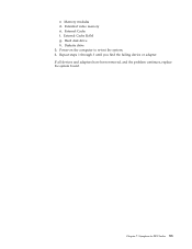
c. Memory modules d. Extended video memory e. Symptom-to re-test the system. 4. Diskette drive 3. Chapter 7. Hard disk drive h. If all devices and adapters have been removed, and the problem continues, replace the system board. Repeat steps 1 through 3 until you find the failing device or adapter. External Cache RAM g. Power-on the computer to -FRU Index 83 External Cache f.
c. Memory modules d. Extended video memory e. Symptom-to re-test the system. 4. Diskette drive 3. Chapter 7. Hard disk drive h. If all devices and adapters have been removed, and the problem continues, replace the system board. Repeat steps 1 through 3 until you find the failing device or adapter. External Cache RAM g. Power-on the computer to -FRU Index 83 External Cache f.

Hardware Maintenance Manual
Page 94
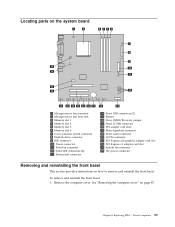
Locations The following illustration will help you locate the major FRUs in the computer. 1 Heat sink and fan assembly 2 Microprocessor 3 Memory modules 4 Optical drive 5 Diskette drive 6 Front bezel 7 Power switch/LED assembly 8 Internal speaker 9 Front audio/USB assembly 10 Hard disk drive 11 System board 12 System fan 13 Power supply 88 Hardware Maintenance Manual
Locations The following illustration will help you locate the major FRUs in the computer. 1 Heat sink and fan assembly 2 Microprocessor 3 Memory modules 4 Optical drive 5 Diskette drive 6 Front bezel 7 Power switch/LED assembly 8 Internal speaker 9 Front audio/USB assembly 10 Hard disk drive 11 System board 12 System fan 13 Power supply 88 Hardware Maintenance Manual
Hardware Maintenance Manual
Page 95
... computer cover" on how to remove and reinstall the front bezel. Locating parts on the system board 1 Microprocessor fan connector 2 Microprocessor and heat sink 3 Memory slot 1 4 Memory slot 2 5 Memory slot 3 6 Memory slot 4 7 Cover presence switch connector 8 Diskette drive connector 9 IDE connector 10 Power connector 11 Front fan connector 12 SATA IDE connectors (4) 13 Front...
... computer cover" on how to remove and reinstall the front bezel. Locating parts on the system board 1 Microprocessor fan connector 2 Microprocessor and heat sink 3 Memory slot 1 4 Memory slot 2 5 Memory slot 3 6 Memory slot 4 7 Cover presence switch connector 8 Diskette drive connector 9 IDE connector 10 Power connector 11 Front fan connector 12 SATA IDE connectors (4) 13 Front...


