(English) User Guide - Lenovo H50 Series
Page 42
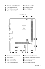
Hardware clear CMOS jumper Front panel connector Front USB connectors (2) Front audio connector LPC debug header Power fan header Mini PCI-E slot Lenovo H50-05 12 3 4 5 12 11 10 9 87 6 Microprocessor and heat sink Memory slots (2) Clear CMOS jumper SATA connectors (2) Front USB connectors (2) Microprocessor fan header Hard disk drive power connector Front panel connector Mini PCI-E slot Front audio connector User Guide 37
Hardware clear CMOS jumper Front panel connector Front USB connectors (2) Front audio connector LPC debug header Power fan header Mini PCI-E slot Lenovo H50-05 12 3 4 5 12 11 10 9 87 6 Microprocessor and heat sink Memory slots (2) Clear CMOS jumper SATA connectors (2) Front USB connectors (2) Microprocessor fan header Hard disk drive power connector Front panel connector Mini PCI-E slot Front audio connector User Guide 37

(English) User Guide - Lenovo H50 Series
Page 49
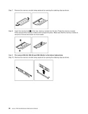
Position the new memory module over the memory connector. Make sure the notch on the memory module is correctly aligned with the connector key on the system board. For Lenovo H50-05, H50-50 and H50-55 refer to "Completing the installation". 44 User Guide Push the memory module straight down into the connector until the retaining clips close. 5. Remove the memory module being replaced by opening the retaining clips as shown. 4. Refer to the below instructions: 3.
Position the new memory module over the memory connector. Make sure the notch on the memory module is correctly aligned with the connector key on the system board. For Lenovo H50-05, H50-50 and H50-55 refer to "Completing the installation". 44 User Guide Push the memory module straight down into the connector until the retaining clips close. 5. Remove the memory module being replaced by opening the retaining clips as shown. 4. Refer to the below instructions: 3.

Lenovo H50 Series Hardware Maintenance Manual
Page 3
Lenovo H50 Series Hardware Maintenance Manual Machine Types: 90C1 [H50-00]; 90BH [H50-05]; 90B6 [H50-50 ES]; 90B7 [H50-50 Non-ES]; 90BF [H50-55 ES]; 90BG [H50-55 Non-ES]
Lenovo H50 Series Hardware Maintenance Manual Machine Types: 90C1 [H50-00]; 90BH [H50-05]; 90B6 [H50-50 ES]; 90B7 [H50-50 Non-ES]; 90BF [H50-55 ES]; 90BG [H50-55 Non-ES]

Lenovo H50 Series Hardware Maintenance Manual
Page 5
...and changing settings 13 Using passwords 13 Enabling or disabling a device 15 Selecting a startup device 16 Exiting the Lenovo BIOS Setup Utility program . . 17 Chapter 6. Safety information 3 General safety 3 Electrical safety 3 Safety inspection...11 Chapter 5. General information . . . 85 Additional Service Information 85 © Copyright Lenovo 2014 iii FRU lists-H50-00 . . . . . 55 Chapter 10. FRU lists-H50-05 . . . . . 61 Chapter 11. FRU lists-H50-55 . . . . . 77 Chapter 13. FRU lists-H50-50 . . . . . 69 Chapter 12. About this manual 1 Important Safety ...
...and changing settings 13 Using passwords 13 Enabling or disabling a device 15 Selecting a startup device 16 Exiting the Lenovo BIOS Setup Utility program . . 17 Chapter 6. Safety information 3 General safety 3 Electrical safety 3 Safety inspection...11 Chapter 5. General information . . . 85 Additional Service Information 85 © Copyright Lenovo 2014 iii FRU lists-H50-00 . . . . . 55 Chapter 10. FRU lists-H50-05 . . . . . 61 Chapter 11. FRU lists-H50-55 . . . . . 77 Chapter 13. FRU lists-H50-50 . . . . . 69 Chapter 12. About this manual 1 Important Safety ...

Lenovo H50 Series Hardware Maintenance Manual
Page 33
Microprocessor and heat sink 2. Clear CMOS jumper 6. SATA connectors (2) 8. Microprocessor fan header 3. Memory slots (2) 4. Front panel connector 5 9 87 6 7. Mini PCI-E slot 9. PCI express X 16 adapter slot Chapter 7. Front USB connectors (2) 10. Hard disk drive power connector 5. Lenovo H50-05 12 3 4 12 11 10 1. PCI express X 1 adapter slot 12. Locating connectors, controls and components 27 Front audio connector 11.
Microprocessor and heat sink 2. Clear CMOS jumper 6. SATA connectors (2) 8. Microprocessor fan header 3. Memory slots (2) 4. Front panel connector 5 9 87 6 7. Mini PCI-E slot 9. PCI express X 16 adapter slot Chapter 7. Front USB connectors (2) 10. Hard disk drive power connector 5. Lenovo H50-05 12 3 4 12 11 10 1. PCI express X 1 adapter slot 12. Locating connectors, controls and components 27 Front audio connector 11.
Lenovo H50 Series Hardware Maintenance Manual
Page 44
Press the memory module firmly and pivot the memory module until it snaps into the slot. Insert the notched end 1 of the new memory module into place. Make sure that the memory module is secured in the slot and does not move easily. For Lenovo H50-05, H50-50 and H50-55refer to the below instructions: Step 10. Step 8. Remove the memory module being replaced by opening the retaining clips as shown. 38 Lenovo H50 SeriesHardware Maintenance Manual Step 9. Step 7. Remove the memory module being replaced by opening the retaining clips as shown.
Press the memory module firmly and pivot the memory module until it snaps into the slot. Insert the notched end 1 of the new memory module into place. Make sure that the memory module is secured in the slot and does not move easily. For Lenovo H50-05, H50-50 and H50-55refer to the below instructions: Step 10. Step 8. Remove the memory module being replaced by opening the retaining clips as shown. 38 Lenovo H50 SeriesHardware Maintenance Manual Step 9. Step 7. Remove the memory module being replaced by opening the retaining clips as shown.

Lenovo H50 Series Hardware Maintenance Manual
Page 67
... SB20F54953 SB20F54956 SB20F54959 SB20F76029 SB20F54951 SB20F54954 SB20F54957 SB20F76027 SB20F76030 SPP0G06453 SPP0G06442 SPP0G06448 SPP0G06427 SPP0G06443 SPP0G06449 SPP0G06441 SPP0G06440 SPP0G06450 SPP0G06438 SPP0G06445 © Copyright Lenovo 2014 61 identifies parts that are fairly simple to read and understand all the safety information before replacing any FRUs. Chapter 10. ... • N-identifies parts that have a 1 or 2 in the CRU column are not to be replaced by the customer. FRU lists-H50-05 This chapter lists the information on the field replaceable units (FRUs).
... SB20F54953 SB20F54956 SB20F54959 SB20F76029 SB20F54951 SB20F54954 SB20F54957 SB20F76027 SB20F76030 SPP0G06453 SPP0G06442 SPP0G06448 SPP0G06427 SPP0G06443 SPP0G06449 SPP0G06441 SPP0G06440 SPP0G06450 SPP0G06438 SPP0G06445 © Copyright Lenovo 2014 61 identifies parts that are fairly simple to read and understand all the safety information before replacing any FRUs. Chapter 10. ... • N-identifies parts that have a 1 or 2 in the CRU column are not to be replaced by the customer. FRU lists-H50-05 This chapter lists the information on the field replaceable units (FRUs).


