B505-11 - Lenovo B505

Related Manual Pages


Similar Questions

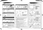
Wall Bracket Adapter B Series All In 0ne As Described Pages 11 And 12 Of The
(Posted by davidpayne001 11 years ago)
Find free Lenovo B505 manuals and user guides available at ManualOwl.com. Try out our unique manual viewer allowing you to interact with manuals from directly within your browser!
View thousands of Lenovo B505 user reviews and customer ratings available at ReviewOwl.com.
Complete Lenovo customer service contact information including steps to reach representatives, hours of operation, customer support links and more from ContactHelp.com.
See detailed Lenovo customer service rankings, employee comments and much more from our sister site.
Find comprehensive Lenovo recall information updated hourly on RecallOwl.com.