Hardware Maintenance Manual
Page 5
... cover 71 Accessing system board components and drives . 72 Replacing a memory module 73 Replacing the CMOS battery 74 Replacing the power supply 75 ...9357, 9439, 9488, 9702, 9708, 9709, 9789, 9851, 9948 91 © Copyright Lenovo 2005, 2010 v Contents Chapter 1. Diagnostics 35 PC-Doctor for Windows 35 PC-Doctor for Windows...The ThinkVantage Productivity Center program . . 29 Additional information resources 29 Specifications 29 Types 7066, 7098, 9352, 9359, 9482, 9487, 9622, 9704, 9794, 9859, 9785, 9807, 9952 . . 29 Types 7065, 7096, 9351, 9358, 9438, 9481, 9489, 9703, 9784, 9788...
... cover 71 Accessing system board components and drives . 72 Replacing a memory module 73 Replacing the CMOS battery 74 Replacing the power supply 75 ...9357, 9439, 9488, 9702, 9708, 9709, 9789, 9851, 9948 91 © Copyright Lenovo 2005, 2010 v Contents Chapter 1. Diagnostics 35 PC-Doctor for Windows 35 PC-Doctor for Windows...The ThinkVantage Productivity Center program . . 29 Additional information resources 29 Specifications 29 Types 7066, 7098, 9352, 9359, 9482, 9487, 9622, 9704, 9794, 9859, 9785, 9807, 9952 . . 29 Types 7065, 7096, 9351, 9358, 9438, 9481, 9489, 9703, 9784, 9788...

Hardware Maintenance Manual
Page 6
...9482, 9487, 9622, 9704, 9785, 9794, 9807, 9859, 9952 119 Locations 119 Front connectors 119 Rear connectors 119 Computer components 120 System board connectors 121 Opening the cover 122 Accessing system board components and drives 123 Replacing an adapter card 124 Replacing a memory module 124 Replacing the battery...features 776 FRU lists 143 Machine Type 6176 143 Machine Type 6177 158 Machine Type 6178 173 Machine Type 6179 187 vi ThinkCentre Hardware Maintenance Manual Machine Type 6305 202 Machine Type 7064 218 Machine Type 7065 233 Machine Type 7066 248 Machine Type ...
...9482, 9487, 9622, 9704, 9785, 9794, 9807, 9859, 9952 119 Locations 119 Front connectors 119 Rear connectors 119 Computer components 120 System board connectors 121 Opening the cover 122 Accessing system board components and drives 123 Replacing an adapter card 124 Replacing a memory module 124 Replacing the battery...features 776 FRU lists 143 Machine Type 6176 143 Machine Type 6177 158 Machine Type 6178 173 Machine Type 6179 187 vi ThinkCentre Hardware Maintenance Manual Machine Type 6305 202 Machine Type 7064 218 Machine Type 7065 233 Machine Type 7066 248 Machine Type ...

Hardware Maintenance Manual
Page 54
See "Updating (flashing) BIOS from a CD-ROM or diskette" on page 775 2. Flash the system. System board 1. Run memory test 4. See "Updating (flashing) BIOS from a CD-ROM or diskette" on page 775 3. System board 1. Re-start the test, if necessary 1. ...Re-start the test to review the log file 2. See "Running tests" on page 775 2. System board 1. Press F3 to reset the log file 46 ThinkCentre Hardware Maintenance Manual System board 1. System board 1. System board 1. Flash the system. Flash the system. Run Setup 2. See "Updating (flashing) BIOS from a...
See "Updating (flashing) BIOS from a CD-ROM or diskette" on page 775 2. Flash the system. System board 1. Run memory test 4. See "Updating (flashing) BIOS from a CD-ROM or diskette" on page 775 3. System board 1. Re-start the test, if necessary 1. ...Re-start the test to review the log file 2. See "Running tests" on page 775 2. System board 1. Press F3 to reset the log file 46 ThinkCentre Hardware Maintenance Manual System board 1. System board 1. System board 1. Flash the system. Flash the system. Run Setup 2. See "Updating (flashing) BIOS from a...
Hardware Maintenance Manual
Page 55
...-ROM or diskette" on page 775 2. Flash the system. See "Updating (flashing) BIOS from a CD-ROM or diskette" on page 775 2. Flash the system. Run memory test 4.
...-ROM or diskette" on page 775 2. Flash the system. See "Updating (flashing) BIOS from a CD-ROM or diskette" on page 775 2. Flash the system. Run memory test 4.
Hardware Maintenance Manual
Page 61
... or diskette" on page 775 3. If a component is called out, make sure it is connected and/or enabled. Remove USB device(s) and re-test 2. Run memory test 4. Run setup and check for conflicts 2. Symptom-to review the log file 2. Replace the component under function test 1. Replace component under test 1. System board...
... or diskette" on page 775 3. If a component is called out, make sure it is connected and/or enabled. Remove USB device(s) and re-test 2. Run memory test 4. Run setup and check for conflicts 2. Symptom-to review the log file 2. Replace the component under function test 1. Replace component under test 1. System board...

Hardware Maintenance Manual
Page 70
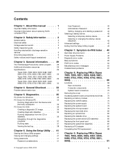
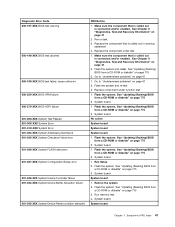
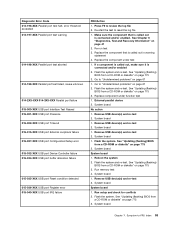
...775 3. See "Updating (flashing) BIOS from a CD-ROM or diskette" on page 67 2. Cache, if removable 2. Check power supply voltages 3. Replace the memory module called out by the test 2. Diskette Drive Cable 2. Hard Disk Drive Cable 2. Flash system 2. System board No action 1. Flash the system and re-...test. System board No action 1. CD-ROM Drive Cable 2. System board No action 1. System board 62 ThinkCentre Hardware Maintenance Manual Check power supply voltages 3. Replace component under function test 1. Microprocessor No action 1.
...775 3. See "Updating (flashing) BIOS from a CD-ROM or diskette" on page 67 2. Cache, if removable 2. Check power supply voltages 3. Replace the memory module called out by the test 2. Diskette Drive Cable 2. Hard Disk Drive Cable 2. Flash system 2. System board No action 1. Flash the system and re-...test. System board No action 1. CD-ROM Drive Cable 2. System board No action 1. System board 62 ThinkCentre Hardware Maintenance Manual Check power supply voltages 3. Replace component under function test 1. Microprocessor No action 1.

Hardware Maintenance Manual
Page 72
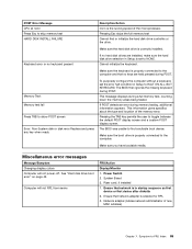
..."Diagnostics, Test and Recovery Information" on the screen. CMOS checksum error - Perform a Boot block recovery. Replace the system board. Replace the memory module(s). 3. Replace the system board. POST error codes Each time you turn on the system, it performs a series of tests that CMOS ...has become corrupt due to a weak CMOS battery. 64 ThinkCentre Hardware Maintenance Manual Checksum of the system and some basic system-board operations • Checks the memory operation • Starts the video operation • Verifies that the boot drive is ...
..."Diagnostics, Test and Recovery Information" on the screen. CMOS checksum error - Perform a Boot block recovery. Replace the system board. Replace the memory module(s). 3. Replace the system board. POST error codes Each time you turn on the system, it performs a series of tests that CMOS ...has become corrupt due to a weak CMOS battery. 64 ThinkCentre Hardware Maintenance Manual Checksum of the system and some basic system-board operations • Checks the memory operation • Starts the video operation • Verifies that the boot drive is ...
Hardware Maintenance Manual
Page 73
... of the microprocessor. Symptom-to HALT ON ALL, BUT KEYBOARD. Cannot initialize the keyboard. The BIOS then ignores the missing keyboard during memory testing, additional information appears. Miscellaneous error messages Message/Symptom Changing display colors Computer will not RPL from server FRU/Action Display/Monitor 1.... gives specifics about the type and location of new MAC address) Chapter 7. POST Error Message CPU at nnnn Press Esc to skip memory test HARD DISK INSTALL FAILURE Keyboard error or no keys are installed, make sure the hard disk drive selection in Setup is enabled...
... of the microprocessor. Symptom-to HALT ON ALL, BUT KEYBOARD. Cannot initialize the keyboard. The BIOS then ignores the missing keyboard during memory testing, additional information appears. Miscellaneous error messages Message/Symptom Changing display colors Computer will not RPL from server FRU/Action Display/Monitor 1.... gives specifics about the type and location of new MAC address) Chapter 7. POST Error Message CPU at nnnn Press Esc to skip memory test HARD DISK INSTALL FAILURE Keyboard error or no keys are installed, make sure the hard disk drive selection in Setup is enabled...

Hardware Maintenance Manual
Page 74
... Setup/Configuration (see "Starting the Setup Utility program" on LAN® 3. Diskette Drive 2. Diskette Drive 2. System Board 66 ThinkCentre Hardware Maintenance Manual Network adapter (advise network administrator of characters and color bars 1. System Board "Insert a Diskette" icon appears with... 45. Display 2. See "Hard disk drive boot error" on page 1. Hard Disk Drive Cable Incorrect memory size during POST 1. Display or illegible display) 2. Memory Module 3. Video adapter (if present) 3. System Board Power-on indicator or hard disk drive in the...
... Setup/Configuration (see "Starting the Setup Utility program" on LAN® 3. Diskette Drive 2. Diskette Drive 2. System Board 66 ThinkCentre Hardware Maintenance Manual Network adapter (advise network administrator of characters and color bars 1. System Board "Insert a Diskette" icon appears with... 45. Display 2. See "Hard disk drive boot error" on page 1. Hard Disk Drive Cable Incorrect memory size during POST 1. Display or illegible display) 2. Memory Module 3. Video adapter (if present) 3. System Board Power-on indicator or hard disk drive in the...
Hardware Maintenance Manual
Page 75
...this computer has a parallel ATA hard disk drive, make sure that the hard disk drive is jumpered as a slave. 1. Extended video memory e. network b. Check startup sequence 2. Check the network adapter LED status Serial or parallel port device failure (system board port) 1. ..., replace the system board. External devices (modem, printer, or mouse) b. Diskette drive 3. System Board 5. Second device - External Device 3. Memory modules d. Symptom-to re-test the system. 4. If network administrator is jumpered as a master and the optical drive is using LCCM Hybrid disk...
...this computer has a parallel ATA hard disk drive, make sure that the hard disk drive is jumpered as a slave. 1. Extended video memory e. network b. Check startup sequence 2. Check the network adapter LED status Serial or parallel port device failure (system board port) 1. ..., replace the system board. External devices (modem, printer, or mouse) b. Diskette drive 3. System Board 5. Second device - External Device 3. Memory modules d. Symptom-to re-test the system. 4. If network administrator is jumpered as a master and the optical drive is using LCCM Hybrid disk...

Hardware Maintenance Manual
Page 78
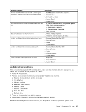
... FRUs in the computer. 1 Fan plenum, fan, and heat sink 2 Microprocessor 3 Optical drive 4 Power switch/LED assembly 5 Hard disk drive 6 Diskette drive 7 Front panel card 8 Memory modules 9 System board 10 Power supply System board connectors This illustration is to help locate the various system board connectors. 70...
... FRUs in the computer. 1 Fan plenum, fan, and heat sink 2 Microprocessor 3 Optical drive 4 Power switch/LED assembly 5 Hard disk drive 6 Diskette drive 7 Front panel card 8 Memory modules 9 System board 10 Power supply System board connectors This illustration is to help locate the various system board connectors. 70...

Hardware Maintenance Manual
Page 79
Chapter 8. Unplug all attached devices. 2. 1 Microprocessor and heat sink 2 Microprocessor fan connector 3 Memory connector 1 4 Memory connector 2 5 Power connector 6 Diskette drive connector 7 IDE connector 8 Power fan connector 9 Serial ATA connectors (4) 10 Clear CMOS/Recovery jumper 11 Front panel connector 12 Front ...
Chapter 8. Unplug all attached devices. 2. 1 Microprocessor and heat sink 2 Microprocessor fan connector 3 Memory connector 1 4 Memory connector 2 5 Power connector 6 Diskette drive connector 7 IDE connector 8 Power fan connector 9 Serial ATA connectors (4) 10 Clear CMOS/Recovery jumper 11 Front panel connector 12 Front ...

Hardware Maintenance Manual
Page 80
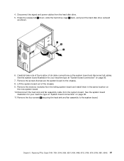
... computer cover and slide the cover to remove completely. 3. This includes power cords, input/output (I/O) cables, and any locking devices such as memory, the battery, and CMOS. Accessing system board components and drives You might have to remove the PCI adapter in order to gain access to ...the battery. 72 ThinkCentre Hardware Maintenance Manual 3. See "Removing the cover" on page 71. 2. Disconnect all cables attached to the computer. 4. In some models, you ...
... computer cover and slide the cover to remove completely. 3. This includes power cords, input/output (I/O) cables, and any locking devices such as memory, the battery, and CMOS. Accessing system board components and drives You might have to remove the PCI adapter in order to gain access to ...the battery. 72 ThinkCentre Hardware Maintenance Manual 3. See "Removing the cover" on page 71. 2. Disconnect all cables attached to the computer. 4. In some models, you ...

Hardware Maintenance Manual
Page 81
Pull upward on page 72. 3. Remove the cover. Remove the memory module being replaced by opening the retaining clips as shown. Replacing a memory module This procedure describes how to access the memory connectors. See "Accessing system board components and drives" on the handle to remove, you can either disconnect the cables from the chassis... assembly completely from the rear of the drives or leave them connected. You might have to remove the drive bay assembly to remove and replace a memory module. 1.
Pull upward on page 72. 3. Remove the cover. Remove the memory module being replaced by opening the retaining clips as shown. Replacing a memory module This procedure describes how to access the memory connectors. See "Accessing system board components and drives" on the handle to remove, you can either disconnect the cables from the chassis... assembly completely from the rear of the drives or leave them connected. You might have to remove the drive bay assembly to remove and replace a memory module. 1.

Hardware Maintenance Manual
Page 82
.... 6. Remove the cover. Install the new battery. 74 ThinkCentre Hardware Maintenance Manual CAUTION: When replacing the lithium battery, use only Part Number 33F8354 or an equivalent type battery recommended by the manufacturer. Remove the old battery. 5. Position the replacement memory module over the memory connector. Replacing the CMOS battery If the CMOS battery...
.... 6. Remove the cover. Install the new battery. 74 ThinkCentre Hardware Maintenance Manual CAUTION: When replacing the lithium battery, use only Part Number 33F8354 or an equivalent type battery recommended by the manufacturer. Remove the old battery. 5. Position the replacement memory module over the memory connector. Replacing the CMOS battery If the CMOS battery...

Hardware Maintenance Manual
Page 85
... system board illustration for your machine type at "System board connectors" on page 70. 6. See "Replacing the hard disk drive" on page 72. 5. Remove the memory modules from the microprocessor. 13. See the system board illustration for your machine type at "System board connectors" on page 70. 11. See "Accessing system...
... system board illustration for your machine type at "System board connectors" on page 70. 6. See "Replacing the hard disk drive" on page 72. 5. Remove the memory modules from the microprocessor. 13. See the system board illustration for your machine type at "System board connectors" on page 70. 11. See "Accessing system...

Hardware Maintenance Manual
Page 100
... connector 17 PCI adapter connectors (2) Computer components The following illustration will help you locate the major FRUs in the computer. 1 Microprocessor fan and heat sink 2 Memory modules (2) 3 Battery 4 PCI Express x1 adapter connector 5 PCI adapter card 6 PCI adapter connector 7 PCI Express x16 graphics adapter connector 8 Cover presence (Intrusion) switch 9 Rear fan... assembly 10 Power supply System board connectors This illustration is to help locate the various components and connectors on the system board. 92 ThinkCentre Hardware Maintenance Manual
... connector 17 PCI adapter connectors (2) Computer components The following illustration will help you locate the major FRUs in the computer. 1 Microprocessor fan and heat sink 2 Memory modules (2) 3 Battery 4 PCI Express x1 adapter connector 5 PCI adapter card 6 PCI adapter connector 7 PCI Express x16 graphics adapter connector 8 Cover presence (Intrusion) switch 9 Rear fan... assembly 10 Power supply System board connectors This illustration is to help locate the various components and connectors on the system board. 92 ThinkCentre Hardware Maintenance Manual

Hardware Maintenance Manual
Page 101
..., or tapes) from electrical outlets. Unplug all power cords from the drives, and turn off all attached devices. 2. 1 Microprocessor and heat sink 2 Microprocessor fan connector 3 Memory connector 1 4 Memory connector 2 5 Power connector 6 Diskette drive connector 7 IDE connector 8 Power fan connector 9 Serial ATA connectors (4) 10 Clear CMOS/Recovery jumper 11 Front panel connector 12...
..., or tapes) from electrical outlets. Unplug all power cords from the drives, and turn off all attached devices. 2. 1 Microprocessor and heat sink 2 Microprocessor fan connector 3 Memory connector 1 4 Memory connector 2 5 Power connector 6 Diskette drive connector 7 IDE connector 8 Power fan connector 9 Serial ATA connectors (4) 10 Clear CMOS/Recovery jumper 11 Front panel connector 12...
Hardware Maintenance Manual
Page 105
... Carefully take note of the location of the chassis. 9. Remove the four screws 1 securing the heat sink and fan assembly to the chassis. 8. Remove the memory modules from the failing system board and install them in the same location on the system board and disconnect all cable connections on the new...
... Carefully take note of the location of the chassis. 9. Remove the four screws 1 securing the heat sink and fan assembly to the chassis. 8. Remove the memory modules from the failing system board and install them in the same location on the system board and disconnect all cable connections on the new...

Hardware Maintenance Manual
Page 111
Go to lay the computer on its side. 2. See "System board connectors" on the system board. Make sure the notch 1 on the memory aligns correctly with the connector key 2 on page 92. 3. See the system board illustration for your machine type at "System board connectors" on...FRUs (Types 7064, 7094, 9349, 9356, 9357, 9439, 9488, 9702, 9708, 9709, 9789, 9851, 9948) 103 Position the new memory module over the memory connector. Connect the heat sink and fan assembly cable to remove and replace a memory module. 1. See "Removing the cover" on page 92. 16. Push Chapter 9. 14. Replacing...
Go to lay the computer on its side. 2. See "System board connectors" on the system board. Make sure the notch 1 on the memory aligns correctly with the connector key 2 on page 92. 3. See the system board illustration for your machine type at "System board connectors" on...FRUs (Types 7064, 7094, 9349, 9356, 9357, 9439, 9488, 9702, 9708, 9709, 9789, 9851, 9948) 103 Position the new memory module over the memory connector. Connect the heat sink and fan assembly cable to remove and replace a memory module. 1. See "Removing the cover" on page 92. 16. Push Chapter 9. 14. Replacing...


