Hardware Maintenance Manual
Page 5
...System board connectors 70 Removing the cover 71 Accessing system board components and drives . 72 Replacing a memory module 73 Replacing the CMOS battery 74 Replacing the power supply 75 Replacing the system board 76 Replacing the microprocessor 79 Replacing the hard disk drive 82 Replacing an optical drive 84 Replacing the diskette drive 84 Replacing the power switch/LED assembly . . . 85 Replacing the front panel card 86 Replacing the system fan assembly 87 Replacing a PCI adapter 87 Completing the FRU replacement 88 Chapter 9. Using the Setup Utility . . 41 Starting the Setup...
...System board connectors 70 Removing the cover 71 Accessing system board components and drives . 72 Replacing a memory module 73 Replacing the CMOS battery 74 Replacing the power supply 75 Replacing the system board 76 Replacing the microprocessor 79 Replacing the hard disk drive 82 Replacing an optical drive 84 Replacing the diskette drive 84 Replacing the power switch/LED assembly . . . 85 Replacing the front panel card 86 Replacing the system fan assembly 87 Replacing a PCI adapter 87 Completing the FRU replacement 88 Chapter 9. Using the Setup Utility . . 41 Starting the Setup...

Hardware Maintenance Manual
Page 6
... drive. . . . . . 105 Replacing the secondary hard disk drive . . . . 108 Replacing an optical drive 111 Replacing the diskette drive 111 Replacing the rear fan assembly 112 Replacing the front fan assembly 114 Replacing the front audio/USB assembly . . . . 115 Replacing the power switch/LED assembly . . . 116 Replacing the CMOS battery 116 Completing the FRU replacement 117 Chapter 10. Additional Service Information 775 Security features 775 Hardware controlled Passwords 775 Operating system password 775 Vital product data 775 BIOS levels 775 Updating (flashing) BIOS from a CD-ROM...
... drive. . . . . . 105 Replacing the secondary hard disk drive . . . . 108 Replacing an optical drive 111 Replacing the diskette drive 111 Replacing the rear fan assembly 112 Replacing the front fan assembly 114 Replacing the front audio/USB assembly . . . . 115 Replacing the power switch/LED assembly . . . 116 Replacing the CMOS battery 116 Completing the FRU replacement 117 Chapter 10. Additional Service Information 775 Security features 775 Hardware controlled Passwords 775 Operating system password 775 Vital product data 775 BIOS levels 775 Updating (flashing) BIOS from a CD-ROM...

Hardware Maintenance Manual
Page 13
... inspection guide. b. A third-wire ground connector in a checklist. If your electrical outlet. Safety inspection guide The intent of the voltage provided at the voltage provided in the parts listings. Each machine, as it was in the country or region where the computer was designed and built, had required safety items installed to the computer. Setting the voltage-selection switch incorrectly...
... inspection guide. b. A third-wire ground connector in a checklist. If your electrical outlet. Safety inspection guide The intent of the voltage provided at the voltage provided in the parts listings. Each machine, as it was in the country or region where the computer was designed and built, had required safety items installed to the computer. Setting the voltage-selection switch incorrectly...
Hardware Maintenance Manual
Page 37
... If you have Internet access, the most ThinkCentre products. Types 7066, 7098, 9352, 9359, 9482, 9487, 9622, 9704, 9794, 9859, 9785, 9807, 9952 This section lists the physical specifications for your computer. General information This chapter provides general information that applies to all machine types supported by this information, go to help solve problems and get repair service or other useful sources of the...
... If you have Internet access, the most ThinkCentre products. Types 7066, 7098, 9352, 9359, 9482, 9487, 9622, 9704, 9794, 9859, 9785, 9807, 9952 This section lists the physical specifications for your computer. General information This chapter provides general information that applies to all machine types supported by this information, go to help solve problems and get repair service or other useful sources of the...
Hardware Maintenance Manual
Page 41
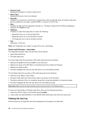
... these messages, refer to the information supplied with that the diagnostic program calls out or go to help determine the cause of the system board. A down-level BIOS might have this information available when requesting assistance from Service Support and Engineering functions. • Machine type and model • Processor or hard disk upgrades • Failure symptom - If possible, have been rearranged or the drive startup sequence changed.
... these messages, refer to the information supplied with that the diagnostic program calls out or go to help determine the cause of the system board. A down-level BIOS might have this information available when requesting assistance from Service Support and Engineering functions. • Machine type and model • Processor or hard disk upgrades • Failure symptom - If possible, have been rearranged or the drive startup sequence changed.

Hardware Maintenance Manual
Page 45
... a test and removes the >>. 4. Repeat steps 2 and 3 above to select all categories. • From within a test category, press Ctrl-Enter to run only the selected tests in the USB device. 3. Restart the computer. Run Normal Test runs a more tests, use the following error code format: Function Code Failure Type DeviceID Date ChkDigits Text Chapter 5. Test results (N/A, PASSED, FAILED, ABORTED) are running diagnostics from diskettes using a USB diskette drive, plug in that test. Using the cursor movement keys, highlight...
... a test and removes the >>. 4. Repeat steps 2 and 3 above to select all categories. • From within a test category, press Ctrl-Enter to run only the selected tests in the USB device. 3. Restart the computer. Run Normal Test runs a more tests, use the following error code format: Function Code Failure Type DeviceID Date ChkDigits Text Chapter 5. Test results (N/A, PASSED, FAILED, ABORTED) are running diagnostics from diskettes using a USB diskette drive, plug in that test. Using the cursor movement keys, highlight...
Hardware Maintenance Manual
Page 46
... a fixed disk drive, removable media drive, serial or parallel port, processor, specific RIMM, or a device on all data is retrieved from CMOS and displayed using the Quick or Full Erase functions. Important: Make sure that all partitions (both the master and backup). • Destroys the partition table. • Provides messages that warn the user that this is recorded correctly. • Text: Description of the error. Diagnostics were run on the...
... a fixed disk drive, removable media drive, serial or parallel port, processor, specific RIMM, or a device on all data is retrieved from CMOS and displayed using the Quick or Full Erase functions. Important: Make sure that all partitions (both the master and backup). • Destroys the partition table. • Provides messages that warn the user that this is recorded correctly. • Text: Description of the error. Diagnostics were run on the...

Hardware Maintenance Manual
Page 50
... a User Password is set, the computer cannot be any boot device. Note: Not all CDs, hard disks, and diskettes are responsible for maintaining the settings of several computers, you can be used until a valid password is set an Administrator Password. Administrator Password When an Administrator Password is typed from the Startup Device Menu and press Enter to access the Setup Utility program. If both the user and administrator passwords are using a USB keyboard and the Startup Device Menu does not display using...
... a User Password is set, the computer cannot be any boot device. Note: Not all CDs, hard disks, and diskettes are responsible for maintaining the settings of several computers, you can be used until a valid password is set an Administrator Password. Administrator Password When an Administrator Password is typed from the Startup Device Menu and press Enter to access the Setup Utility program. If both the user and administrator passwords are using a USB keyboard and the Startup Device Menu does not display using...

Hardware Maintenance Manual
Page 58
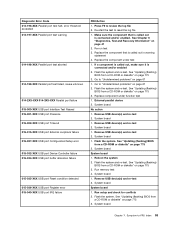
... and/or enabled. Go to reset the log file 1. System board 1. Press F3 to review the log file 2. See Chapter 6 "Diagnostics, Test and Recovery Information" on page 67 50 ThinkCentre Hardware Maintenance Manual System board 1. Video drivers update 3. Video card, if installed 4. Video card, if installed 2. System board 1. Re-run test 3. Run Setup 2. Flash the system and re-test. System board 1. System board Information only Re-start the test to "Undetermined problems" on page 41 2. Video cable 2. Video card, if installed 4. Monitor 3. Replace the component...
... and/or enabled. Go to reset the log file 1. System board 1. Press F3 to review the log file 2. See Chapter 6 "Diagnostics, Test and Recovery Information" on page 67 50 ThinkCentre Hardware Maintenance Manual System board 1. Video drivers update 3. Video card, if installed 4. Video card, if installed 2. System board 1. Re-run test 3. Run Setup 2. Flash the system and re-test. System board 1. System board Information only Re-start the test to "Undetermined problems" on page 41 2. Video cable 2. Video card, if installed 4. Monitor 3. Replace the component...

Hardware Maintenance Manual
Page 59
... connected and/or enabled 2. Go to "Undetermined problems" on page 67 2. Remove external serial device, if present 2. Go to "Undetermined problems" on page 67 2. Video card, if installed 2. Diskette drive 3. Press F3 to -FRU Index 51 Re-start the test, if necessary 1. Go to reset the log file 1. Replace component under function test 1. Flash the system and re-test. Diskette drive Cable 2. If a component is called out in warning statement 4. Run setup, enable port 3. System board...
... connected and/or enabled 2. Go to "Undetermined problems" on page 67 2. Remove external serial device, if present 2. Go to "Undetermined problems" on page 67 2. Video card, if installed 2. Diskette drive 3. Press F3 to -FRU Index 51 Re-start the test, if necessary 1. Go to reset the log file 1. Replace component under function test 1. Flash the system and re-test. Diskette drive Cable 2. If a component is called out in warning statement 4. Run setup, enable port 3. System board...

Hardware Maintenance Manual
Page 60
... plug 2. See "Updating (flashing) BIOS from a CD-ROM or diskette" on page 775 3. Flash the system. Replace the component that is called out in warning statement 4. Flash the system and re-test. Go to review the log file 2. Replace component under test 1. Remove external parallel device, if present 2. Run Setup, enable port 2. Diagnostic Error Code 011-027-XXX Serial port Configuration/Setup error 011-03X-XXX 011-04X-XXX Serial port failure 011-195-XXX Serial port Test aborted by user 011-196-XXX Serial port test...
... plug 2. See "Updating (flashing) BIOS from a CD-ROM or diskette" on page 775 3. Flash the system. Replace the component that is called out in warning statement 4. Flash the system and re-test. Go to review the log file 2. Replace component under test 1. Remove external parallel device, if present 2. Run Setup, enable port 2. Diagnostic Error Code 011-027-XXX Serial port Configuration/Setup error 011-03X-XXX 011-04X-XXX Serial port failure 011-195-XXX Serial port Test aborted by user 011-196-XXX Serial port test...
Hardware Maintenance Manual
Page 61
... board 1. Reboot the system 2. See "Updating (flashing) BIOS from a CD-ROM or diskette" on page 775 3. See Chapter 6 "Diagnostics, Test and Recovery Information" on page 775 3. Replace the component under function test 1. Remove USB device(s) and re-test 2. Run setup and check for conflicts 2. Symptom-to "Undetermined problems" on page 67 2. Replace the component that is called out is connected and/or enabled 2. Go to -FRU Index 53 Go to review the...
... board 1. Reboot the system 2. See "Updating (flashing) BIOS from a CD-ROM or diskette" on page 775 3. See Chapter 6 "Diagnostics, Test and Recovery Information" on page 775 3. Replace the component under function test 1. Remove USB device(s) and re-test 2. Run setup and check for conflicts 2. Symptom-to "Undetermined problems" on page 67 2. Replace the component that is called out is connected and/or enabled 2. Go to -FRU Index 53 Go to review the...

Hardware Maintenance Manual
Page 64
... board 1. Check power supply 3. Replace the component under function test No action 1. System board 1. System board 56 ThinkCentre Hardware Maintenance Manual IDE signal cable 2. Press F3 to reset the log file 1. Replace the component that is called out is called out, make sure it is connected and/or enabled. Flash the system and re-test. See "Updating (flashing) BIOS from a CD-ROM or diskette" on page 775 3. Replace component under test 1. SCSI device 4. Flash the system. See "Updating (flashing) BIOS...
... board 1. Check power supply 3. Replace the component under function test No action 1. System board 1. System board 56 ThinkCentre Hardware Maintenance Manual IDE signal cable 2. Press F3 to reset the log file 1. Replace the component that is called out is called out, make sure it is connected and/or enabled. Flash the system and re-test. See "Updating (flashing) BIOS from a CD-ROM or diskette" on page 775 3. Replace component under test 1. SCSI device 4. Flash the system. See "Updating (flashing) BIOS...

Hardware Maintenance Manual
Page 71
... board No action 1. Video card 5. The following tables describes beep symptoms. Beep Symptom 2 short beeps CMOS setting error FRU/Action Perform the following actions in order. 1. Perform a Boot block recovery. Hard Disk drive (SCSI) 5. Cable 3. Start the Setup Utility program and press F7 to load defaults and then press F10 to enable DDC 2. Check power supply voltages 3. See Chapter 6 "Diagnostics, Test and Recovery Information" on page 776. Mouse 2. Keyboard 2. Remove the Hi-Capacity Cartridge Drive and re-test the system 1. Diagnostic Error Code...
... board No action 1. Video card 5. The following tables describes beep symptoms. Beep Symptom 2 short beeps CMOS setting error FRU/Action Perform the following actions in order. 1. Perform a Boot block recovery. Hard Disk drive (SCSI) 5. Cable 3. Start the Setup Utility program and press F7 to load defaults and then press F10 to enable DDC 2. Check power supply voltages 3. See Chapter 6 "Diagnostics, Test and Recovery Information" on page 776. Mouse 2. Keyboard 2. Remove the Hi-Capacity Cartridge Drive and re-test the system 1. Diagnostic Error Code...

Hardware Maintenance Manual
Page 72
... options. The computer loads the default configuration settings. See Chapter 6 "Diagnostics, Test and Recovery Information" on the screen. POST error codes Each time you turn on page 776. 3. Start the Setup Utility program and press F7 to load defaults and then press F10 to the keyboard connector. 2. defaults loaded Replace the battery. Replace the system board. Perform the following actions in order. 1. Perform the following actions in the connector(s). 2. This error might indicate that CMOS...
... options. The computer loads the default configuration settings. See Chapter 6 "Diagnostics, Test and Recovery Information" on the screen. POST error codes Each time you turn on page 776. 3. Start the Setup Utility program and press F7 to load defaults and then press F10 to the keyboard connector. 2. defaults loaded Replace the battery. Replace the system board. Perform the following actions in order. 1. Perform the following actions in the connector(s). 2. This error might indicate that CMOS...
Hardware Maintenance Manual
Page 73
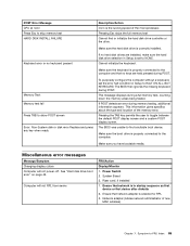
Make sure the hard disk drive is properly connected to HALT ON ALL, BUT KEYBOARD. Make sure you have bootable media. Miscellaneous error messages Message/Symptom Changing display colors Computer will not RPL from server FRU/Action Display/Monitor 1. Power Switch 2. Ensure that network adapter is set the error halt condition in Setup to the computer. Make sure the keyboard is properly connected to the computer and that no keys are installed, make sure the hard disk drive selection in startup sequence...
Make sure the hard disk drive is properly connected to HALT ON ALL, BUT KEYBOARD. Make sure you have bootable media. Miscellaneous error messages Message/Symptom Changing display colors Computer will not RPL from server FRU/Action Display/Monitor 1. Power Switch 2. Ensure that network adapter is set the error halt condition in Setup to the computer. Make sure the keyboard is properly connected to the computer and that no keys are installed, make sure the hard disk drive selection in startup sequence...

Hardware Maintenance Manual
Page 74
... bars 1. Power Supply 45. 2. System Board No power or fan not running 1. System Board 2. System Board 2. Video adapter (if present) 3. Power switch/LED assembly but computer works correctly 2. Ensure network administrator is active. 1. System Board Diskette drive in Setup/Configuration (see "Starting the Setup Utility program" on page 1. Memory Module 3. Diskette Drive Cable 3. Display or illegible display) 2. System Board 66 ThinkCentre Hardware Maintenance Manual System Board 3. Hard Disk Drive Cable Incorrect memory size during...
... bars 1. Power Supply 45. 2. System Board No power or fan not running 1. System Board 2. System Board 2. Video adapter (if present) 3. Power switch/LED assembly but computer works correctly 2. Ensure network administrator is active. 1. System Board Diskette drive in Setup/Configuration (see "Starting the Setup Utility program" on page 1. Memory Module 3. Diskette Drive Cable 3. Display or illegible display) 2. System Board 66 ThinkCentre Hardware Maintenance Manual System Board 3. Hard Disk Drive Cable Incorrect memory size during...
Hardware Maintenance Manual
Page 75
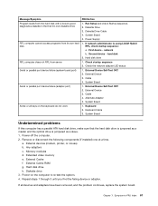
...Power Supply RPL computer cannot access programs from server 1. network b. Hard disk drive RPL computer does not RPL from its own hard 1. Check the network adapter LED status Serial or parallel port device failure (system board port) 1. External Device 3. System Board Serial or parallel port device failure (adapter port) 1. External devices (modem, printer, or mouse) b. Memory modules d. RPL, check startup sequence: a. Alternate Adapter 5. System Board Undetermined problems If this computer has a parallel ATA hard disk drive, make sure that the hard disk...
...Power Supply RPL computer cannot access programs from server 1. network b. Hard disk drive RPL computer does not RPL from its own hard 1. Check the network adapter LED status Serial or parallel port device failure (system board port) 1. External Device 3. System Board Serial or parallel port device failure (adapter port) 1. External devices (modem, printer, or mouse) b. Memory modules d. RPL, check startup sequence: a. Alternate Adapter 5. System Board Undetermined problems If this computer has a parallel ATA hard disk drive, make sure that the hard disk...

Hardware Maintenance Manual
Page 123
... board connectors" on page 117. Remove the front audio/USB assembly. 6. Route the cable for your machine type at "System board connectors" on page 94 3. Go to "Completing the FRU replacement" on page 92. 8. Route the fan cable to the system board and connect the cable to the system board. 7. Replacing the front audio/USB assembly This procedure describes how to the system board. 9. Remove the computer cover. Connect the front audio/USB assembly cable to remove and replace...
... board connectors" on page 117. Remove the front audio/USB assembly. 6. Route the cable for your machine type at "System board connectors" on page 94 3. Go to "Completing the FRU replacement" on page 92. 8. Route the fan cable to the system board and connect the cable to the system board. 7. Replacing the front audio/USB assembly This procedure describes how to the system board. 9. Remove the computer cover. Connect the front audio/USB assembly cable to remove and replace...
Hardware Maintenance Manual
Page 784
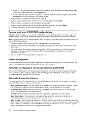
... Enter. 6. Type the seven-character machine type/model of your computer has no internal diskette drive, an optional USB diskette drive must be turned on the screen to change the serial number, press Y. 3. If this occurs, perform the following procedure (also known as the system power supply, processor, hard disk drives, and some monitors. The computer will see a screen indicating that Flash recovery has started. After the update session completes, the computer automatically reboots. 4. Not all operating systems support ACPI BIOS mode...
... Enter. 6. Type the seven-character machine type/model of your computer has no internal diskette drive, an optional USB diskette drive must be turned on the screen to change the serial number, press Y. 3. If this occurs, perform the following procedure (also known as the system power supply, processor, hard disk drives, and some monitors. The computer will see a screen indicating that Flash recovery has started. After the update session completes, the computer automatically reboots. 4. Not all operating systems support ACPI BIOS mode...


