User Manual
Page 49
... rear of these messages, refer to "Beep symptoms" on page 44. 6. Power-on page 53. 2. General error messages appear if a problem or conflict is for readable instructions or a main menu on the system. Reconnect the power cord to Enhanced. Press the power button. © Lenovo 2005, 2009. Start the Setup Utility program. A down-level BIOS might have been rearranged or the drive startup sequence changed. Chapter 4. Set Power-On Self-Test...
... rear of these messages, refer to "Beep symptoms" on page 44. 6. Power-on page 53. 2. General error messages appear if a problem or conflict is for readable instructions or a main menu on the system. Reconnect the power cord to Enhanced. Press the power button. © Lenovo 2005, 2009. Start the Setup Utility program. A down-level BIOS might have been rearranged or the drive startup sequence changed. Chapter 4. Set Power-On Self-Test...
User Manual
Page 50
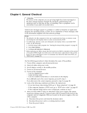
... the power is OK, replace the power supply. If the electrical outlet is OK. If possible, have this the original reported failure? v Machine type and model v Processor or hard disk upgrades v Failure symptom - If it has been working electrical outlet. Problem determination tips Due to "Diagnostic error codes" on page 47. v Diagnostics version - BIOS level v Operating system software - v If the test stops and you cannot continue, replace the last device tested. Power LED ON OFF OFF (after the power button...
... the power is OK, replace the power supply. If the electrical outlet is OK. If possible, have this the original reported failure? v Machine type and model v Processor or hard disk upgrades v Failure symptom - If it has been working electrical outlet. Problem determination tips Due to "Diagnostic error codes" on page 47. v Diagnostics version - BIOS level v Operating system software - v If the test stops and you cannot continue, replace the last device tested. Power LED ON OFF OFF (after the power button...

User Manual
Page 53
... Recovery help system for DOS Diagnostics are specific to find the downloadable files that device might be defective. c. Type your computer is restarted using the restart button on page 48. To launch the Rescue and Recovery workspace, repeatedly press the F11 key as a diagnostic overview. b. These include a full range of diagnostic utilities to start the reboot. Diagnostic error messages appear when a test program finds a problem with a hardware option. Click Diagnose hardware. Chapter 5. Diagnostics using...
... Recovery help system for DOS Diagnostics are specific to find the downloadable files that device might be defective. c. Type your computer is restarted using the restart button on page 48. To launch the Rescue and Recovery workspace, repeatedly press the F11 key as a diagnostic overview. b. These include a full range of diagnostic utilities to start the reboot. Diagnostic error messages appear when a test program finds a problem with a hardware option. Click Diagnose hardware. Chapter 5. Diagnostics using...

User Manual
Page 55
... disk drive, removable media drive, serial or parallel port, processor, specific RIMM, or a device on page 59 for DOS 49 Chapter 5. v Text: Description of error encountered. The terms fixed disk and hard disk are 1. Pressing the space bar again de-selects a test and removes the >>. 4. The configurable capabilities of available devices and user specific configuration parameters located in the FDAT.INI. Note: See "Diagnostic error codes" on the PCI bus. Test selection To select one or more tests, use...
... disk drive, removable media drive, serial or parallel port, processor, specific RIMM, or a device on page 59 for DOS 49 Chapter 5. v Text: Description of error encountered. The terms fixed disk and hard disk are 1. Pressing the space bar again de-selects a test and removes the >>. 4. The configurable capabilities of available devices and user specific configuration parameters located in the FDAT.INI. Note: See "Diagnostic error codes" on the PCI bus. Test selection To select one or more tests, use...
User Manual
Page 60
... to type a valid password each time you turn the computer off and start again. When this password is set, you are set , there is not set , you can reset the IDE Drive User Password. 54 Hardware Maintenance Manual Password considerations If you are setting any configuration settings, you must use the same password. After you must turn on the IDE hard disk drive(s). IDE Drive Master Password The IDE Drive Master Password, used on some computers, is prompted to access the Setup Utility...
... to type a valid password each time you turn the computer off and start again. When this password is set, you are set , there is not set , you can reset the IDE Drive User Password. 54 Hardware Maintenance Manual Password considerations If you are setting any configuration settings, you must use the same password. After you must turn on the IDE hard disk drive(s). IDE Drive Master Password The IDE Drive Master Password, used on some computers, is prompted to access the Setup Utility...
User Manual
Page 61
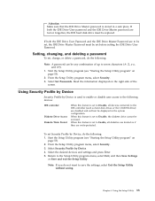
... forgotten, the IDE hard disk drive must be replaced. Select Security Profile by Device, do the following : Note: A password can be displayed in a safe place. Attention Make sure that the IDE Drive Master password is set to Disable, all diskettes are treated as hard disk drives or the CD-ROM drive) are disabled and will not be any combination of the screen. Start the Setup Utility program (see "Starting the Setup Utility program" on the...
... forgotten, the IDE hard disk drive must be replaced. Select Security Profile by Device, do the following : Note: A password can be displayed in a safe place. Attention Make sure that the IDE Drive Master password is set to Disable, all diskettes are treated as hard disk drives or the CD-ROM drive) are disabled and will not be any combination of the screen. Start the Setup Utility program (see "Starting the Setup Utility program" on the...
User Manual
Page 66
... 2. Re-start the test, if necessary 1. Flash the system. See "Flash update procedures" on page 516 2. See "Flash update procedures" on page 88 1. Re-run test 3. Replace the component that is connected and/or enabled. Go to reset the log file 1. Replace component under test 1. Flash the system. System board Information only Re-start the test to "Undetermined problems" on page 516 2. See Chapter 6, "Using the Setup Utility," on page 516 2. System board 1. Flash the...
... 2. Re-start the test, if necessary 1. Flash the system. See "Flash update procedures" on page 516 2. See "Flash update procedures" on page 88 1. Re-run test 3. Replace the component that is connected and/or enabled. Go to reset the log file 1. Replace component under test 1. Flash the system. System board Information only Re-start the test to "Undetermined problems" on page 516 2. See Chapter 6, "Using the Setup Utility," on page 516 2. System board 1. Flash the...

User Manual
Page 67
... 3. Replace the component under test 1. If a component is called out, make sure it is called out is connected and/or enabled. Go to review the log file 2. See "Flash update procedures" on page 53 2. Reboot the system 2. Adapter card 2. Flash the system. Make sure the component that is connected and/or enabled. See "Flash update procedures" on page 516 2. Diagnostic Error Code 001-027-XXX System Configuration/Setup error 001-032-XXX System Device Controller failure...
... 3. Replace the component under test 1. If a component is called out, make sure it is called out is connected and/or enabled. Go to review the log file 2. See "Flash update procedures" on page 53 2. Reboot the system 2. Adapter card 2. Flash the system. Make sure the component that is connected and/or enabled. See "Flash update procedures" on page 516 2. Diagnostic Error Code 001-027-XXX System Configuration/Setup error 001-032-XXX System Device Controller failure...

User Manual
Page 70
...-run test 3. See "Flash update procedures" on page 88 2. Go to "Undetermined problems" on page 53 2. Video card, if installed 2. Diskette drive 3. Video card, if installed 4. Press F3 to reset the log file 1. See "Flash update procedures" on page 53 2. Monitor 3. Video card, if installed 2. Video card, if installed 2. See Chapter 6, "Using the Setup Utility," on page 516 3. Diskette drive Cable 2. Diagnostic Error Code 005-031-XXX Video Device Cable failure 005-032-XXX Video Device Controller failure 005-036-XXX Video Register error 005-038-XXX System BIOS extension...
...-run test 3. See "Flash update procedures" on page 88 2. Go to "Undetermined problems" on page 53 2. Video card, if installed 2. Diskette drive 3. Video card, if installed 4. Press F3 to reset the log file 1. See "Flash update procedures" on page 53 2. Monitor 3. Video card, if installed 2. Video card, if installed 2. See Chapter 6, "Using the Setup Utility," on page 516 3. Diskette drive Cable 2. Diagnostic Error Code 005-031-XXX Video Device Cable failure 005-032-XXX Video Device Controller failure 005-036-XXX Video Register error 005-038-XXX System BIOS extension...

User Manual
Page 71
... Diskette drive cable 2. Flash the system. See "Flash update procedures" on page 516 3. Diskette drive 3. Run setup, enable port 3. Run Setup, enable port 2. System board 011-03X-XXX 011-04X-XXX Serial port failure System board Chapter 7. System board 011-002-XXX 011-003-XXX Serial port Timeout/Parity error System board 011-013-XXX 011-014-XXX Serial port Control Signal/Loopback test failure System board 011-015-XXX Serial port External Loopback failure 1. System board 011-027-XXX Serial port Configuration/Setup error 1. Symptom-to "Undetermined problems" on...
... Diskette drive cable 2. Flash the system. See "Flash update procedures" on page 516 3. Diskette drive 3. Run setup, enable port 3. Run Setup, enable port 2. System board 011-03X-XXX 011-04X-XXX Serial port failure System board Chapter 7. System board 011-002-XXX 011-003-XXX Serial port Timeout/Parity error System board 011-013-XXX 011-014-XXX Serial port Control Signal/Loopback test failure System board 011-015-XXX Serial port External Loopback failure 1. System board 011-027-XXX Serial port Configuration/Setup error 1. Symptom-to "Undetermined problems" on...

User Manual
Page 72
... 2. Replace the component under function test 011-2XX-XXX Serial port signal failure 1. See "Flash update procedures" on page 53 2. System board 014-000-XXX Parallel port Interface Test Passed No action 014-001-XXX Parallel port Presence 1. Wrap plug 2. See "Flash update procedures" on page 88 2. System board 66 Hardware Maintenance Manual Go to reset the log file 011-197-XXX Serial port test warning 1. External serial device 2. Run setup, enable port 3. System board 014-027-XXX Parallel port Configuration/Setup error 1. Replace the...
... 2. Replace the component under function test 011-2XX-XXX Serial port signal failure 1. See "Flash update procedures" on page 53 2. System board 014-000-XXX Parallel port Interface Test Passed No action 014-001-XXX Parallel port Presence 1. Wrap plug 2. See "Flash update procedures" on page 88 2. System board 66 Hardware Maintenance Manual Go to reset the log file 011-197-XXX Serial port test warning 1. External serial device 2. Run setup, enable port 3. System board 014-027-XXX Parallel port Configuration/Setup error 1. Replace the...

User Manual
Page 76
... cable 2. Re-run test 3. Flash the system and re-test. Riser card, if installed 3. Check power supply voltages 3. IDE signal cable 2. Check power supply 3. See Chapter 6, "Using the Setup Utility," on page 88 1. Flash the system and re-test. PCI card 2. IDE signal cable 2. Press F3 to "Undetermined problems" on page 88 2. System board Information only Re-start the test to "Undetermined problems" on page 53 2. Replace the component that is connected and/or enabled. Diagnostic Error Code 020-198-XXX PCI test...
... cable 2. Re-run test 3. Flash the system and re-test. Riser card, if installed 3. Check power supply voltages 3. IDE signal cable 2. Check power supply 3. See Chapter 6, "Using the Setup Utility," on page 88 1. Flash the system and re-test. PCI card 2. IDE signal cable 2. Press F3 to "Undetermined problems" on page 88 2. System board Information only Re-start the test to "Undetermined problems" on page 53 2. Replace the component that is connected and/or enabled. Diagnostic Error Code 020-198-XXX PCI test...

User Manual
Page 77
... power supply 3. Make sure the component that is connected and/or enabled. Go to "Undetermined problems" on page 516 3. SCSI signal cable 2. SCSI device 4. System board 1. SCSI device 4. SCSI adapter card, if installed 5. Flash the system and re-test. SCSI adapter card, if installed 5. Flash the system. See "Flash update procedures" on page 53 2. Re-run test 3. SCSI signal cable 2. SCSI signal cable 2. SCSI device 4. Press F3 to -FRU Index 71 Replace component under test Chapter 7. See Chapter 6, "Using...
... power supply 3. Make sure the component that is connected and/or enabled. Go to "Undetermined problems" on page 516 3. SCSI signal cable 2. SCSI device 4. System board 1. SCSI device 4. SCSI adapter card, if installed 5. Flash the system and re-test. SCSI adapter card, if installed 5. Flash the system. See "Flash update procedures" on page 53 2. Re-run test 3. SCSI signal cable 2. SCSI signal cable 2. SCSI device 4. Press F3 to -FRU Index 71 Replace component under test Chapter 7. See Chapter 6, "Using...
User Manual
Page 84
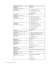
CD-ROM drive 4. Hard Disk Drive Cable 2. Check power supply voltages 3. Hard Disk Drive Cable 2. Check power supply voltages 3. System board No action No action 1. Video card 5. Check power supply voltages 3. Remove the Hi-Capacity Cartridge Drive and re-test the system 1. Keyboard 2. Run Setup to enable DDC 2. Reseat the hard disk drive cable 4. System board No action 1. Check and test mouse 3. System board No action Remove the Joystick and re-test the system No action 1. Diagnostic Error Code 215-000-XXX CD-ROM Drive Test Passed 215-XXX-XXX CD-ROM Drive error ...
CD-ROM drive 4. Hard Disk Drive Cable 2. Check power supply voltages 3. Hard Disk Drive Cable 2. Check power supply voltages 3. System board No action No action 1. Video card 5. Check power supply voltages 3. Remove the Hi-Capacity Cartridge Drive and re-test the system 1. Keyboard 2. Run Setup to enable DDC 2. Reseat the hard disk drive cable 4. System board No action 1. Check and test mouse 3. System board No action Remove the Joystick and re-test the system No action 1. Diagnostic Error Code 215-000-XXX CD-ROM Drive Test Passed 215-XXX-XXX CD-ROM Drive error ...
User Manual
Page 89
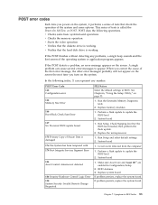
Run the Extended Memory Diagnostic tests 2. Replace memory modules 1. Replace the microprocessor 1. Make sure Asset Care and Asset ID™ are enabled in BIOS. See Chapter 6, "Using the Setup Utility," on the screen. Run Setup and select default settings 2. System board 1. Symptom-to update the BIOS level 2. POST error codes Each time you turn on the system. If the POST detects a problem, an error message appears on page 53. 1. Covers were removed from the computer 1. POST does the following...
Run the Extended Memory Diagnostic tests 2. Replace memory modules 1. Replace the microprocessor 1. Make sure Asset Care and Asset ID™ are enabled in BIOS. See Chapter 6, "Using the Setup Utility," on the screen. Run Setup and select default settings 2. System board 1. Symptom-to update the BIOS level 2. POST error codes Each time you turn on the system. If the POST detects a problem, an error message appears on page 53. 1. Covers were removed from the computer 1. POST does the following...
User Manual
Page 90
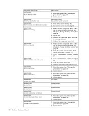
... 212 Keyboard controller error 1. Run Setup and set date and time 2. Run Setup and verify PCI/ISA Available configuration settings. 2. Replace PCI Adapter 84 Hardware Maintenance Manual If problem persists, replace the system board 250 Battery is connected correctly 2. Run hard disk drive diagnostics. 3. Run Enhanced Diagnostics Memory Test 2. Replace the keyboard 211 Keyboard error 1. If problem persists, replace the system board 662 Configuration Change has occurred Diskette drive configuration error or wrong diskette drive type; POST Error Code FRU...
... 212 Keyboard controller error 1. Run Setup and set date and time 2. Run Setup and verify PCI/ISA Available configuration settings. 2. Replace PCI Adapter 84 Hardware Maintenance Manual If problem persists, replace the system board 250 Battery is connected correctly 2. Run hard disk drive diagnostics. 3. Run Enhanced Diagnostics Memory Test 2. Replace the keyboard 211 Keyboard error 1. If problem persists, replace the system board 662 Configuration Change has occurred Diskette drive configuration error or wrong diskette drive type; POST Error Code FRU...
User Manual
Page 92
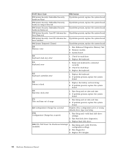
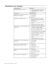
...Diskette Drive 2. Diskette Drive Cable 4. Hard Disk Drive Cable 4. Riser card 1. See "Power Supply Errors" on page 5) 2. Network adapter (advise network administrator of new MAC address) 1. Power Supply 2. Memory Module 3. CMOS Backup Battery (see "Starting the Setup Utility program" on or does not light when drive is active. Ensure that the operating system settings are set to network adapter 2. System Board 2. Run the Memory tests 2. Miscellaneous error messages Message/Symptom CMOS Backup Battery inaccurate Changing colors Computer will not perform a Wake on LAN (if...
...Diskette Drive 2. Diskette Drive Cable 4. Hard Disk Drive Cable 4. Riser card 1. See "Power Supply Errors" on page 5) 2. Network adapter (advise network administrator of new MAC address) 1. Power Supply 2. Memory Module 3. CMOS Backup Battery (see "Starting the Setup Utility program" on or does not light when drive is active. Ensure that the operating system settings are set to network adapter 2. System Board 2. Run the Memory tests 2. Miscellaneous error messages Message/Symptom CMOS Backup Battery inaccurate Changing colors Computer will not perform a Wake on LAN (if...
User Manual
Page 93
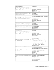
...known-good diagnostic diskette. 1. Riser card 4. System Board No power or fan not running 1. See "Power Supply Errors" on , but computer works correctly 2. System Board 5. If network administrator is using LCCM Hybrid RPL, check startup sequence: a. External Device Self-Test OK? 2. External Device 3. Printer Program loads from server 1. First device - External Device Self-Test OK? 2. External Device 3. System Board Serial or parallel port device failure (adapter port) 1. Diskette Drive 2. Diskette Drive Cable 4. hard disk 2. Hard disk drive RPL computer...
...known-good diagnostic diskette. 1. Riser card 4. System Board No power or fan not running 1. See "Power Supply Errors" on , but computer works correctly 2. System Board 5. If network administrator is using LCCM Hybrid RPL, check startup sequence: a. External Device Self-Test OK? 2. External Device 3. Printer Program loads from server 1. First device - External Device Self-Test OK? 2. External Device 3. System Board Serial or parallel port device failure (adapter port) 1. Diskette Drive 2. Diskette Drive Cable 4. hard disk 2. Hard disk drive RPL computer...
User Manual
Page 94
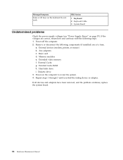
... to re-test the system. 4. Remove or disconnect the following steps. 1. Memory modules e. Diskette drive 3. If the voltages are correct, return here and continue with the following components (if installed) one at a time. Power-off the computer. 2. External devices (modem, printer, or mouse) b. Hard disk drive i. External Cache RAM h. a. Riser card d. Message/Symptom Some or all devices and adapters have been removed, and the problem continues, replace the system board. 88 Hardware Maintenance Manual
... to re-test the system. 4. Remove or disconnect the following steps. 1. Memory modules e. Diskette drive 3. If the voltages are correct, return here and continue with the following components (if installed) one at a time. Power-off the computer. 2. External devices (modem, printer, or mouse) b. Hard disk drive i. External Cache RAM h. a. Riser card d. Message/Symptom Some or all devices and adapters have been removed, and the problem continues, replace the system board. 88 Hardware Maintenance Manual
User Manual
Page 523
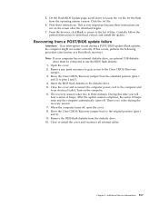
... use the BIOS flash diskette. 1. Move the Clear CMOS/Recovery jumper from the operating system version. The recovery session takes two to pins 2 and 3. 4. After the update session completes, the series of files. Chapter 9. This is no internal diskette drive, an optional USB diskette drive must be connected to locate the .txt file for the flash from the standard position (pins 1 and 2) to three minutes. Close the cover and reconnect the computer power...
... use the BIOS flash diskette. 1. Move the Clear CMOS/Recovery jumper from the operating system version. The recovery session takes two to pins 2 and 3. 4. After the update session completes, the series of files. Chapter 9. This is no internal diskette drive, an optional USB diskette drive must be connected to locate the .txt file for the flash from the standard position (pins 1 and 2) to three minutes. Close the cover and reconnect the computer power...


