User Manual
Page 5
...drivers 9 Removing the cover 10 Locating components 11 Identifying parts on the system board . . . . . 11 Installing memory 12 Installing adapters 14 Installing internal drives 16 Drive specifications 16 Installing a drive 17 Installing security features 20 Padlock loop ...(flashing) BIOS from the Setup Utility program . . . . . 28 Appendix A. Notices 41 Television output notice 42 Trademarks 42 Index 43 © Lenovo 2005. Contents Important safety information v Conditions that require immediate action . . . . . v General safety guidelines vi Service vi Power cords and power...
...drivers 9 Removing the cover 10 Locating components 11 Identifying parts on the system board . . . . . 11 Installing memory 12 Installing adapters 14 Installing internal drives 16 Drive specifications 16 Installing a drive 17 Installing security features 20 Padlock loop ...(flashing) BIOS from the Setup Utility program . . . . . 28 Appendix A. Notices 41 Television output notice 42 Trademarks 42 Index 43 © Lenovo 2005. Contents Important safety information v Conditions that require immediate action . . . . . v General safety guidelines vi Service vi Power cords and power...
User Manual
Page 17
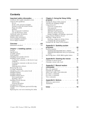
Note: Use only the parts provided by model type) © Lenovo 2005. System information The following information covers a variety of the computer features and preinstalled software. Installing options ThinkCentre Features This chapter provides an introduction to the features and options that come with the option. When installing an option, use the Setup ...overview of models. Portions © IBM Corp. 2004,2005. 1 See Chapter 2, "Using the Setup Utility program," on page v. For information for your computer by adding memory, adapters, or drives. Chapter 1.
Note: Use only the parts provided by model type) © Lenovo 2005. System information The following information covers a variety of the computer features and preinstalled software. Installing options ThinkCentre Features This chapter provides an introduction to the features and options that come with the option. When installing an option, use the Setup ...overview of models. Portions © IBM Corp. 2004,2005. 1 See Chapter 2, "Using the Setup Utility program," on page v. For information for your computer by adding memory, adapters, or drives. Chapter 1.
User Manual
Page 18
... four double data rate (DDR or DDR2, depending on model) dual inline memory modules (DIMMs) v 512 KB flash memory for system programs Internal drives v 3.5-inch, 1.44 MB diskette drive v Serial Advanced Technology Attachment (SATA) internal hard disk drive v Optical drive (some models) Video subsystem v ...
... four double data rate (DDR or DDR2, depending on model) dual inline memory modules (DIMMs) v 512 KB flash memory for system programs Internal drives v 3.5-inch, 1.44 MB diskette drive v Serial Advanced Technology Attachment (SATA) internal hard disk drive v Optical drive (some models) Video subsystem v ...

User Manual
Page 21
... - Optical drives such as printers, joysticks, and scanners - v Outside the United States and Canada, contact your Lenovo reseller, or Lenovo marketing representative. Installing options 5 Audio devices, such as external speakers for certain options. Security device, such as printers... and external drives - PCI Express (x1) adapter - System memory, called dual inline memory modules (DIMMs) - Parallel port devices, such as a...
... - Optical drives such as printers, joysticks, and scanners - v Outside the United States and Canada, contact your Lenovo reseller, or Lenovo marketing representative. Installing options 5 Audio devices, such as external speakers for certain options. Security device, such as printers... and external drives - PCI Express (x1) adapter - System memory, called dual inline memory modules (DIMMs) - Parallel port devices, such as a...

User Manual
Page 22
... metal surface. This reduces static electricity in the computer without setting the option down. v When possible, remove the option and install it . Handle adapters and memory modules by the edges. v When you install a new option, touch the static-protective package containing the option to help you make the connection and install...
... metal surface. This reduces static electricity in the computer without setting the option down. v When possible, remove the option and install it . Handle adapters and memory modules by the edges. v When you install a new option, touch the static-protective package containing the option to help you make the connection and install...

User Manual
Page 27
... computer functions and supports a variety of devices that are factory-installed or that you locate the various components in your computer. * XXXXXXXXX* * XXXXXXXXX* 1 Power supply 2 Memory modules 3 PCI Express (x1) adapter connector 4 PCI adapter connector 5 PCI Express (x16) graphics adapter connector 6 Battery 7 Microprocessor and heat sink Identifying parts on the system...
... computer functions and supports a variety of devices that are factory-installed or that you locate the various components in your computer. * XXXXXXXXX* * XXXXXXXXX* 1 Power supply 2 Memory modules 3 PCI Express (x1) adapter connector 4 PCI adapter connector 5 PCI Express (x16) graphics adapter connector 6 Battery 7 Microprocessor and heat sink Identifying parts on the system...

User Manual
Page 28
... mode. The following illustration shows the locations of system memory. The type of memory required depends on the system board. 1 12v power connector 2 Diskette drive connector 3 Speaker connector 4 Memory connector 4 5 Memory connector 3 6 Memory connector 2 7 Memory connector 1 8 Clear CMOS/Recovery jumper 9 Front panel...connector 1 21 Battery 22 Microprocessor 23 Microprocessor fan connector 24 Microprocessor heat sink Installing memory Your computer has four connectors for installing dual inline memory modules (DIMMs) that provide up to a maximum of 4.0 GB of parts ...
... mode. The following illustration shows the locations of system memory. The type of memory required depends on the system board. 1 12v power connector 2 Diskette drive connector 3 Speaker connector 4 Memory connector 4 5 Memory connector 3 6 Memory connector 2 7 Memory connector 1 8 Clear CMOS/Recovery jumper 9 Front panel...connector 1 21 Battery 22 Microprocessor 23 Microprocessor fan connector 24 Microprocessor heat sink Installing memory Your computer has four connectors for installing dual inline memory modules (DIMMs) that provide up to a maximum of 4.0 GB of parts ...

User Manual
Page 29
... assembly upward to gain access to the edge of 128 MB, 256 MB, 512 MB, and 1 GB sizes. Chapter 1. 1. v If the two memory connectors closest to memory addressing limitations of the Intel 915G Family chipset, and is usually not visible until more than the amount of... type of the system board are 184-pin, 2.5 V and can be less than 3.0 GB of physical memory installed. v If the two memory connectors closest to the system board. * XXXXXXXXX* * XXXXXXXXX* 3. System memory as reported in the ″System Summary″ section of the Setup Utility or the operating system might be...
... assembly upward to gain access to the edge of 128 MB, 256 MB, 512 MB, and 1 GB sizes. Chapter 1. 1. v If the two memory connectors closest to memory addressing limitations of the Intel 915G Family chipset, and is usually not visible until more than the amount of... type of the system board are 184-pin, 2.5 V and can be less than 3.0 GB of physical memory installed. v If the two memory connectors closest to the system board. * XXXXXXXXX* * XXXXXXXXX* 3. System memory as reported in the ″System Summary″ section of the Setup Utility or the operating system might be...

User Manual
Page 30
5. Make sure that the notch 1 on the memory module aligns correctly with another option, go to "Replacing the cover and connecting the cables" on the system board....to gain access to 340 mm (13.4 inches) long in PCI adapter connector 1 and PCI adapter connector 2. Push the memory module straight down into the memory connector until the retaining clips close. See "Removing the cover" on page 10. 2. What to the appropriate section. ... (x1) adapter connector, and one PCI Express (x16) graphics adapter connector. Remove the computer cover. Position the memory module over the...
5. Make sure that the notch 1 on the memory module aligns correctly with another option, go to "Replacing the cover and connecting the cables" on the system board....to gain access to 340 mm (13.4 inches) long in PCI adapter connector 1 and PCI adapter connector 2. Push the memory module straight down into the memory connector until the retaining clips close. See "Removing the cover" on page 10. 2. What to the appropriate section. ... (x1) adapter connector, and one PCI Express (x16) graphics adapter connector. Remove the computer cover. Position the memory module over the...

User Manual
Page 37
... of your computer when a padlock is installed. however, no charging or maintenance throughout its life; An error message is displayed when you can use of memory that locks the cover to set a password. Password protection To deter unauthorized use the Setup Utility program to your computer, you turn off the computer...
... of your computer when a padlock is installed. however, no charging or maintenance throughout its life; An error message is displayed when you can use of memory that locks the cover to set a password. Password protection To deter unauthorized use the Setup Utility program to your computer, you turn off the computer...

User Manual
Page 41
... are available: v User Password v Administrator Password v IDE Drive User Password v IDE Drive Master Password You do the following information: © Lenovo 2005. If your computer and data. Press and hold the F1 key then turn off the computer. 2. The Setup Utility might override any of... when turning on your computer, you must use your computer. When working with the Setup Utility program menu, you should read -only memory (EEPROM) of each screen. The following sections. Viewing and changing settings The Setup Utility program menu lists items that hardware has been...
... are available: v User Password v Administrator Password v IDE Drive User Password v IDE Drive Master Password You do the following information: © Lenovo 2005. If your computer and data. Press and hold the F1 key then turn off the computer. 2. The Setup Utility might override any of... when turning on your computer, you must use your computer. When working with the Setup Utility program menu, you should read -only memory (EEPROM) of each screen. The following sections. Viewing and changing settings The Setup Utility program menu lists items that hardware has been...
User Manual
Page 45
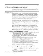
...can understand. Turn on the World Wide Web. 2. Your computer system board has a module called electrically erasable programmable read-only memory (EEPROM, also referred to change the configuration and setup of software that is built into electrical signals that the computer hardware can...computer. System program updates are prompted to select a language, press the number on the World Wide Web (see the Quick Reference). Lenovo might make changes and enhancements to the language then press Enter. 4. Instructions for using a flash update diskette or by starting your ...
...can understand. Turn on the World Wide Web. 2. Your computer system board has a module called electrically erasable programmable read-only memory (EEPROM, also referred to change the configuration and setup of software that is built into electrical signals that the computer hardware can...computer. System program updates are prompted to select a language, press the number on the World Wide Web (see the Quick Reference). Lenovo might make changes and enhancements to the language then press Enter. 4. Instructions for using a flash update diskette or by starting your ...
User Manual
Page 49
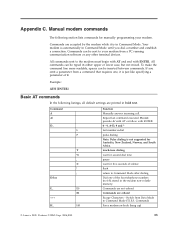
...] Basic AT commands In the following section lists commands for Australia, New Zealand, Norway, and South Africa. Command) Force modem on-hook (hang up) © Lenovo 2005. To make the command line more readable, spaces can be typed in Command Mode. Command A A/ D_ L P T W , @ ! ; DS=n E_ E0... dialing wait for second dial tone pause wait for five seconds of the four telephone numbers (n=0-3) stored in the modem non-volatile memory. Manual modem commands The following listings, all default settings are accepted by the modem while it is automatically in bold text. Commands...
...] Basic AT commands In the following section lists commands for Australia, New Zealand, Norway, and South Africa. Command) Force modem on-hook (hang up) © Lenovo 2005. To make the command line more readable, spaces can be typed in Command Mode. Command A A/ D_ L P T W , @ ! ; DS=n E_ E0... dialing wait for second dial tone pause wait for five seconds of the four telephone numbers (n=0-3) stored in the modem non-volatile memory. Manual modem commands The following listings, all default settings are accepted by the modem while it is automatically in bold text. Commands...

User Manual
Page 50
... Guide Function Force modem off-hook (make busy) Note: H1 command is not supported for Italy Display product-identification code Factory ROM checksum test Internal memory test Firmware ID Reserved ID Low speaker volume Low speaker volume Medium speaker volume High speaker volume Internal speaker off Internal speaker on until carrier...
... Guide Function Force modem off-hook (make busy) Note: H1 command is not supported for Italy Display product-identification code Factory ROM checksum test Internal memory test Firmware ID Reserved ID Low speaker volume Low speaker volume Medium speaker volume High speaker volume Internal speaker off Internal speaker on until carrier...

User Manual
Page 59
installing options (continued) security features 20 K keyboard connector 9 L locating components 11 M memory dual inline memory modules (DIMMs) 12 installing 12 system 12 modem Basic AT commands 33 Extended AT commands 35 Fax Class 1 commands 37 Fax Class 2 commands 37 MNP/V.... 17 internal 2, 16 optical 5 removable media 5 specifications 16 E environment, operating 4 Ethernet connector 9 I information resources xiii input/output (I/O) features 2 installing options adapters 14 internal drives 17 memory modules 12, 13 © Lenovo 2005.
installing options (continued) security features 20 K keyboard connector 9 L locating components 11 M memory dual inline memory modules (DIMMs) 12 installing 12 system 12 modem Basic AT commands 33 Extended AT commands 35 Fax Class 1 commands 37 Fax Class 2 commands 37 MNP/V.... 17 internal 2, 16 optical 5 removable media 5 specifications 16 E environment, operating 4 Ethernet connector 9 I information resources xiii input/output (I/O) features 2 installing options adapters 14 internal drives 17 memory modules 12, 13 © Lenovo 2005.

User Manual
Page 60
replacing the cover 23 S security features 3, 20 padlock loop 21 security profile by device 27 serial connector 9 Setup Utility 25 system board connectors 12 identifying parts 11 location 12 memory 5, 12 system programs 29 U USB connectors 9 using passwords 25 security profile by device 27 V video, subsystem 2 44 User Guide
replacing the cover 23 S security features 3, 20 padlock loop 21 security profile by device 27 serial connector 9 Setup Utility 25 system board connectors 12 identifying parts 11 location 12 memory 5, 12 system programs 29 U USB connectors 9 using passwords 25 security profile by device 27 V video, subsystem 2 44 User Guide


