User Manual
Page 5
...-sensitive devices 5 Installing external options 6 Locating the connectors on the front of your computer 7 Locating the connectors on the system board . . . . . 11 Installing memory 12 Installing adapters 14 Installing internal drives 16 Drive specifications 16 Installing a drive 17 Installing security features 20 Padlock loop 21 Password protection 21 Changing the battery 21 Erasing a lost or forgotten password (clearing CMOS 23 Replacing the cover and connecting the cables. . . 23 Chapter 2. Cleaning the mouse . . . 31 Cleaning an optical mouse 31 Cleaning a mouse with...
...-sensitive devices 5 Installing external options 6 Locating the connectors on the front of your computer 7 Locating the connectors on the system board . . . . . 11 Installing memory 12 Installing adapters 14 Installing internal drives 16 Drive specifications 16 Installing a drive 17 Installing security features 20 Padlock loop 21 Password protection 21 Changing the battery 21 Erasing a lost or forgotten password (clearing CMOS 23 Replacing the cover and connecting the cables. . . 23 Chapter 2. Cleaning the mouse . . . 31 Cleaning an optical mouse 31 Cleaning a mouse with...
User Manual
Page 14
If you suspect a problem with one of these components. Hazardous voltage, current, and energy levels are no serviceable parts inside any part that has this label attached. xii User Guide Power supply statement Never remove the cover on a power supply or any component that has the following label attached. There are present inside these parts, contact a service technician.
If you suspect a problem with one of these components. Hazardous voltage, current, and energy levels are no serviceable parts inside any part that has this label attached. xii User Guide Power supply statement Never remove the cover on a power supply or any component that has the following label attached. There are present inside these parts, contact a service technician.
User Manual
Page 15
... includes basic troubleshooting information, software recovery procedures, help and service information, and warranty information. You can find the following information: v CRU removal and installation instructions v Publications v Troubleshooting information v Parts information v Downloads and drivers v Links to other useful sources of the latest advances in this information, point your needs change. Portions © IBM Corp. 2004,2005. Instructions for selecting a ThinkCentre computer. If you for installing external and internal options are included...
... includes basic troubleshooting information, software recovery procedures, help and service information, and warranty information. You can find the following information: v CRU removal and installation instructions v Publications v Troubleshooting information v Parts information v Downloads and drivers v Links to other useful sources of the latest advances in this information, point your needs change. Portions © IBM Corp. 2004,2005. Instructions for selecting a ThinkCentre computer. If you for installing external and internal options are included...
User Manual
Page 17
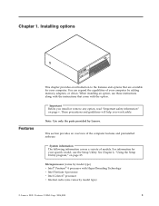
... model type) v Intel® Pentium® 4 processor with the option. Portions © IBM Corp. 2004,2005. 1 Note: Use only the parts provided by Lenovo. Chapter 1. Installing options ThinkCentre Features This chapter provides an introduction to the features and options that come with HyperThreading Technology v Intel Pentium 4 processor v Intel Celeron® processor v Internal cache (size varies by adding memory, adapters, or drives. Important Before you work safely. See Chapter 2, "Using the Setup Utility...
... model type) v Intel® Pentium® 4 processor with the option. Portions © IBM Corp. 2004,2005. 1 Note: Use only the parts provided by Lenovo. Chapter 1. Installing options ThinkCentre Features This chapter provides an introduction to the features and options that come with HyperThreading Technology v Intel Pentium 4 processor v Intel Celeron® processor v Internal cache (size varies by adding memory, adapters, or drives. Important Before you work safely. See Chapter 2, "Using the Setup Utility...
User Manual
Page 18
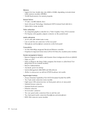
... v 512 KB flash memory for system programs Internal drives v 3.5-inch, 1.44 MB diskette drive v Serial Advanced Technology Attachment (SATA) internal hard disk drive v Optical drive (some models) Video subsystem v An integrated graphics controller for a Video Graphics Array (VGA) monitor v PCI Express (x16) graphics adapter connector on the system board Audio subsystem v AC'97 with ADI 1981B Audio Codec v Line in and line out connectors on the rear panel v Microphone and headphone connectors on the front panel Connectivity v 10/100/1000 Mbps integrated Broadcom Ethernet controller v Peripheral...
... v 512 KB flash memory for system programs Internal drives v 3.5-inch, 1.44 MB diskette drive v Serial Advanced Technology Attachment (SATA) internal hard disk drive v Optical drive (some models) Video subsystem v An integrated graphics controller for a Video Graphics Array (VGA) monitor v PCI Express (x16) graphics adapter connector on the system board Audio subsystem v AC'97 with ADI 1981B Audio Codec v Line in and line out connectors on the rear panel v Microphone and headphone connectors on the front panel Connectivity v 10/100/1000 Mbps integrated Broadcom Ethernet controller v Peripheral...
User Manual
Page 19
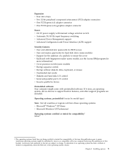
... adapter connectors v One PCI Express (x1) adapter connector v One PCI Express (x16) graphics adapter connector Power v 310 W power supply with manual voltage selection switch v Automatic 50/60 Hz input frequency switching v Advanced Power Management support v Advanced Configuration and Power Interface (ACPI) support Security features v User and administrator passwords for BIOS access v User and master passwords for hard disk drive (some models) v Startup sequence control v Startup without diskette drive, keyboard, or mouse v Unattended start mode v Diskette and hard disk I/O control v Serial...
... adapter connectors v One PCI Express (x1) adapter connector v One PCI Express (x16) graphics adapter connector Power v 310 W power supply with manual voltage selection switch v Automatic 50/60 Hz input frequency switching v Advanced Power Management support v Advanced Configuration and Power Interface (ACPI) support Security features v User and administrator passwords for BIOS access v User and master passwords for hard disk drive (some models) v Startup sequence control v Startup without diskette drive, keyboard, or mouse v Unattended start mode v Diskette and hard disk I/O control v Serial...

User Manual
Page 21
... and options. Installing options 5 Hard disk drive - When you are some options in your Lenovo reseller or Lenovo marketing representative. Available options The following telephone numbers: v Within the United States, call 1-800-565-3344 or 1-800-426-2968. Peripheral component interconnect (PCI) adapters - USB devices, such as external modems and digital cameras - See the instructions that come with the option. PCI Express (x16) graphics adapter - When you add an option, do so. Parallel port devices...
... and options. Installing options 5 Hard disk drive - When you are some options in your Lenovo reseller or Lenovo marketing representative. Available options The following telephone numbers: v Within the United States, call 1-800-565-3344 or 1-800-426-2968. Peripheral component interconnect (PCI) adapters - USB devices, such as external modems and digital cameras - See the instructions that come with the option. PCI Express (x16) graphics adapter - When you add an option, do so. Parallel port devices...

User Manual
Page 24
... connectors on the rear of the computer. 1 PCI adapter connector 9 Diagnostic LEDs 2 PCI Express (x1) adapter connector 10 Power connector 3 PCI Express (x16) graphics adapter 11 Audio line out connector connector 4 Ethernet connector 12 Audio line in connector 5 USB connectors 13 VGA monitor connector 6 Mouse connector 14 Serial connector 7 Parallel connector 15 Keyboard connector 8 Serial connector (some models) 16 USB connectors Note: Some connectors on the rear of the computer are color-coded to help you determine where to connect the cables on your computer. 8 User Guide
... connectors on the rear of the computer. 1 PCI adapter connector 9 Diagnostic LEDs 2 PCI Express (x1) adapter connector 10 Power connector 3 PCI Express (x16) graphics adapter 11 Audio line out connector connector 4 Ethernet connector 12 Audio line in connector 5 USB connectors 13 VGA monitor connector 6 Mouse connector 14 Serial connector 7 Parallel connector 15 Keyboard connector 8 Serial connector (some models) 16 USB connectors Note: Some connectors on the rear of the computer are color-coded to help you determine where to connect the cables on your computer. 8 User Guide

User Manual
Page 25
... than eight USB devices, you can purchase a USB hub, which you attach an external audio device, a cable is connected between the audio line out connector of the computer. Chapter 1. Serial connectors Used to attach an external modem, serial printer, or other external recording device. When you can obtain device drivers for a local area network (LAN). Installation instructions are not preinstalled at http://www.lenovo.com/think/support on a stereo system or other devices that use a 9-pin serial connector. Parallel connector Used to...
... than eight USB devices, you can purchase a USB hub, which you attach an external audio device, a cable is connected between the audio line out connector of the computer. Chapter 1. Serial connectors Used to attach an external modem, serial printer, or other external recording device. When you can obtain device drivers for a local area network (LAN). Installation instructions are not preinstalled at http://www.lenovo.com/think/support on a stereo system or other devices that use a 9-pin serial connector. Parallel connector Used to...

User Manual
Page 28
... board. 1 12v power connector 2 Diskette drive connector 3 Speaker connector 4 Memory connector 4 5 Memory connector 3 6 Memory connector 2 7 Memory connector 1 8 Clear CMOS/Recovery jumper 9 Front panel connector 10 PATA IDE connector 11 SATA 4 connector 12 SATA 3 connector 13 SATA 2 connector 14 SATA 1 connector 15 Cover presence switch connector 16 Power supply connector 17 PCI Express (x16) graphics adapter connector 18 PCI Express (x1) adapter connector 19 PCI adapter connector 2 20 PCI adapter connector 1 21 Battery 22 Microprocessor 23 Microprocessor fan connector...
... board. 1 12v power connector 2 Diskette drive connector 3 Speaker connector 4 Memory connector 4 5 Memory connector 3 6 Memory connector 2 7 Memory connector 1 8 Clear CMOS/Recovery jumper 9 Front panel connector 10 PATA IDE connector 11 SATA 4 connector 12 SATA 3 connector 13 SATA 2 connector 14 SATA 1 connector 15 Cover presence switch connector 16 Power supply connector 17 PCI Express (x16) graphics adapter connector 18 PCI Express (x1) adapter connector 19 PCI adapter connector 2 20 PCI adapter connector 1 21 Battery 22 Microprocessor 23 Microprocessor fan connector...
User Manual
Page 33
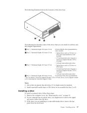
... removable media drive v Optical drive such as CD drive or DVD drive v 3.5-inch hard disk drive (requires a Universal Adapter Bracket, 5.25 to 3.5-inch) * 3 Bay 3 - Install removable media (tape or CD) drives in .) high cannot be installed. 2. If the drive you are greater than 43.0 mm (1.7 in an accessible bay (bay 2 or 3). The following list describes some of the drive bays. Drives that you might need to 3.5-inch, from the front bezel. See "Removing the cover...
... removable media drive v Optical drive such as CD drive or DVD drive v 3.5-inch hard disk drive (requires a Universal Adapter Bracket, 5.25 to 3.5-inch) * 3 Bay 3 - Install removable media (tape or CD) drives in .) high cannot be installed. 2. If the drive you are greater than 43.0 mm (1.7 in an accessible bay (bay 2 or 3). The following list describes some of the drive bays. Drives that you might need to 3.5-inch, from the front bezel. See "Removing the cover...

User Manual
Page 36
... keyboard until a correct password is typed in. 20 User Guide See "Identifying parts on the system board" on page 11. 2. Connect a power connector to the drive. In addition to physical locks, unauthorized use of the signal cable to the drive and the other to "Replacing the cover and connecting the cables" on the system board. Connecting an additional optical drive or parallel ATA hard disk drive 1. See "Identifying parts on the system board" on page 11. 3. Connecting a serial ATA hard disk drive A serial hard disk drive...
... keyboard until a correct password is typed in. 20 User Guide See "Identifying parts on the system board" on page 11. 2. Connect a power connector to the drive. In addition to physical locks, unauthorized use of the signal cable to the drive and the other to "Replacing the cover and connecting the cables" on the system board. Connecting an additional optical drive or parallel ATA hard disk drive 1. See "Identifying parts on the system board" on page 11. 3. Connecting a serial ATA hard disk drive A serial hard disk drive...

User Manual
Page 39
... maintenance or configure position (pins 2 and 3). 6. See "Removing the cover" on your computer. 2. Pivot the drive bay assembly upward to gain access to confirm the updated information in the Setup Utility program. See "Identifying parts on the system board" on for approximately 5 seconds. Move the jumper back to install any removed parts, replace the computer cover, and reconnect any cables that no tools or loose screws are left inside your desktop. Clear...
... maintenance or configure position (pins 2 and 3). 6. See "Removing the cover" on your computer. 2. Pivot the drive bay assembly upward to gain access to confirm the updated information in the Setup Utility program. See "Identifying parts on the system board" on for approximately 5 seconds. Move the jumper back to install any removed parts, replace the computer cover, and reconnect any cables that no tools or loose screws are left inside your desktop. Clear...

User Manual
Page 41
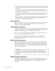
... keys used to set any of the various types of passwords on your computer. The following types of each screen. Starting the Setup Utility program To start the Setup Utility program, do not have to view and change the configuration settings of your computer, regardless of which operating system you should read -only memory (EEPROM) of your computer, you are displayed at the bottom of passwords are available: v User Password v Administrator Password v IDE Drive User Password...
... keys used to set any of the various types of passwords on your computer. The following types of each screen. Starting the Setup Utility program To start the Setup Utility program, do not have to view and change the configuration settings of your computer, regardless of which operating system you should read -only memory (EEPROM) of your computer, you are displayed at the bottom of passwords are available: v User Password v Administrator Password v IDE Drive User Password...
User Manual
Page 42
... Drive User Password is lost or forgotten. If your computer. However, to access the Setup Utility program. v Do not move an IDE hard disk drive to a local area network (LAN), the Wake on . The computer cannot be used to type a valid password each time you are set , you must use your computer. If both a User Password and an IDE Drive User Password and each time you turn on the IDE hard disk drive(s). IDE Drive User Password The IDE Drive User Password...
... Drive User Password is lost or forgotten. If your computer. However, to access the Setup Utility program. v Do not move an IDE hard disk drive to a local area network (LAN), the Wake on . The computer cannot be used to type a valid password each time you are set , you must use your computer. If both a User Password and an IDE Drive User Password and each time you turn on the IDE hard disk drive(s). IDE Drive User Password The IDE Drive User Password...

User Manual
Page 43
... controller (such as expected, use one of the screen. Using the Setup Utility program 27 If both the IDE Drive User password and the IDE Drive Master password are lost or forgotten, the IDE hard disk drive must be set to Enable, all devices connected to select a startup device. Setting, changing, and deleting a password To set to Disable, all diskettes are treated as if they are disabled and will not be accessed. When this feature is set before setting...
... controller (such as expected, use one of the screen. Using the Setup Utility program 27 If both the IDE Drive User password and the IDE Drive Master password are lost or forgotten, the IDE hard disk drive must be set to Enable, all devices connected to select a startup device. Setting, changing, and deleting a password To set to Disable, all diskettes are treated as if they are disabled and will not be accessed. When this feature is set before setting...
User Manual
Page 45
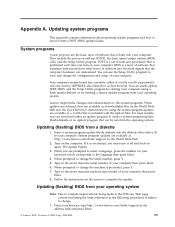
... change the machine type/model, press Y. 7. Type in a .txt file that translates instructions from a POST/BIOS update failure. Updating (flashing) BIOS from the operating system. You can be run from your computer. Updating (flashing) BIOS from your computer using the system program updates are available as flash memory). If it off and back on the World Wide Web (see the Quick Reference). Lenovo might make changes and enhancements to the language then press Enter. 4. The update...
... change the machine type/model, press Y. 7. Type in a .txt file that translates instructions from a POST/BIOS update failure. Updating (flashing) BIOS from the operating system. You can be run from your computer. Updating (flashing) BIOS from your computer using the system program updates are available as flash memory). If it off and back on the World Wide Web (see the Quick Reference). Lenovo might make changes and enhancements to the language then press Enter. 4. The update...

User Manual
Page 46
... beeps. If this time you will automatically turn on page 10. 3. If necessary, refer to Installing adapters to remove any cables that were removed. 14. Move the jumper from the operating system version). 3. Reconnect the power cords for the flash BIOS update (flash from the standard position (pins 1 and 2) to the Clear CMOS/Recovery jumper. 6. Repeats steps 2 through 5 on page 23. 15. Replace the Clear CMOS/Recovery jumper to electrical outlets. 9. See "Replacing the cover and connecting...
... beeps. If this time you will automatically turn on page 10. 3. If necessary, refer to Installing adapters to remove any cables that were removed. 14. Move the jumper from the operating system version). 3. Reconnect the power cords for the flash BIOS update (flash from the standard position (pins 1 and 2) to the Clear CMOS/Recovery jumper. 6. Repeats steps 2 through 5 on page 23. 15. Replace the Clear CMOS/Recovery jumper to electrical outlets. 9. See "Replacing the cover and connecting...
User Manual
Page 52
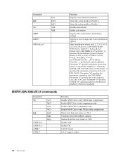
... Direct data link only (same as \N1) V.42 data link with V.8/V.32 Annex A. Command &W_ %E_ +MS? +MS=? +MS=a,b,c,e,f &V1 &W0 &W1 %E0 %E1 Function Display Last Connection Statistics Stores the active profile as Profile 0 Stores the active profile as Profile 1 Disable auto-retrain Enable auto-retrain Displays the current Select Modulation settings Displays a list of support values 36 User Guide
... Direct data link only (same as \N1) V.42 data link with V.8/V.32 Annex A. Command &W_ %E_ +MS? +MS=? +MS=a,b,c,e,f &V1 &W0 &W1 %E0 %E1 Function Display Last Connection Statistics Stores the active profile as Profile 0 Stores the active profile as Profile 1 Disable auto-retrain Enable auto-retrain Displays the current Select Modulation settings Displays a list of support values 36 User Guide

User Manual
Page 59
... password considerations 25 erasing 23 IDE drive master 26 IDE drive user 26 lost or forgotten 23 setting, changing, deleting 27 physical specifications 4 power Advanced Configuration and Power Interface (ACPI) support 3 Advanced Power Management support 3 R recovering from a POST/BIOS update failure 30 removing the cover 10 43 Index A adapters connectors 14 installing 14 peripheral component interconnect (PCI) 5 audio line in connector 9 audio line out connector 9 audio, subsystem 2 B battery location 11 boot-block recovery 30 C cables, connecting 23 changing the battery 21 cleaning the mouse...
... password considerations 25 erasing 23 IDE drive master 26 IDE drive user 26 lost or forgotten 23 setting, changing, deleting 27 physical specifications 4 power Advanced Configuration and Power Interface (ACPI) support 3 Advanced Power Management support 3 R recovering from a POST/BIOS update failure 30 removing the cover 10 43 Index A adapters connectors 14 installing 14 peripheral component interconnect (PCI) 5 audio line in connector 9 audio line out connector 9 audio, subsystem 2 B battery location 11 boot-block recovery 30 C cables, connecting 23 changing the battery 21 cleaning the mouse...


