User Manual
Page 5
... connectors on the front of your computer 18 Obtaining device drivers 20 Removing the cover 20 Locating components 21 © Lenovo 2005, 2007. Identifying parts on the system board . . . . . 21 Installing memory 24 Installing adapters 25 Installing internal drives 27 Drive specifications 27 Installing a drive 29 Installing security features 33 Padlock loop...
... connectors on the front of your computer 18 Obtaining device drivers 20 Removing the cover 20 Locating components 21 © Lenovo 2005, 2007. Identifying parts on the system board . . . . . 21 Installing memory 24 Installing adapters 25 Installing internal drives 27 Drive specifications 27 Installing a drive 29 Installing security features 33 Padlock loop...
User Manual
Page 9
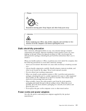
... an option or CRU, do not open the static-protective package containing the part until the instructions direct you to install it down. Handle adapters, memory modules, and other metal surface. This reduces static electricity in the package and your movement. Danger Hazardous moving parts. Never touch exposed circuitry. Static electricity...
... an option or CRU, do not open the static-protective package containing the part until the instructions direct you to install it down. Handle adapters, memory modules, and other metal surface. This reduces static electricity in the package and your movement. Danger Hazardous moving parts. Never touch exposed circuitry. Static electricity...

User Manual
Page 29
Note: Use only the parts provided by adding memory, drives, or adapters. For information for your computer. Portions © IBM Corp. 2005. 11 Important Before you work safely. System information The following information covers ... preinstalled software. You can expand the capabilities of your specific model, use these instructions along with the instructions that are available for your computer by Lenovo. When installing an option, use the Setup Utility. See Chapter 5, "Using the Setup Utility," on page v. Chapter 3. This section provides an overview of models. ...
Note: Use only the parts provided by adding memory, drives, or adapters. For information for your computer. Portions © IBM Corp. 2005. 11 Important Before you work safely. System information The following information covers ... preinstalled software. You can expand the capabilities of your specific model, use these instructions along with the instructions that are available for your computer by Lenovo. When installing an option, use the Setup Utility. See Chapter 5, "Using the Setup Utility," on page v. Chapter 3. This section provides an overview of models. ...
User Manual
Page 30
...® D processor v Intel Core™ 2 Duo processor v AMD Athlon 64 processor v AMD Sempron processor v Internal cache (size varies by model type) Memory v Support for two DDR2 DIMMs v 4 Mb flash memory Internal drives v Internal Serial ATA hard disk drive v Optical drive (some models) v Diskette drive (some models) Video subsystem v An integrated graphics controller...
...® D processor v Intel Core™ 2 Duo processor v AMD Athlon 64 processor v AMD Sempron processor v Internal cache (size varies by model type) Memory v Support for two DDR2 DIMMs v 4 Mb flash memory Internal drives v Internal Serial ATA hard disk drive v Optical drive (some models) v Diskette drive (some models) Video subsystem v An integrated graphics controller...
User Manual
Page 32
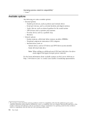
...drives and DVD drives (some available options: v External options - The operating systems listed here are subject to change. System memory, called dual inline memory modules (DIMMs) - Optical drives, such as : - To determine if an operating system has been certified or tested for...- Corrections and additions to press. Peripheral component interconnect (PCI) adapters - For the latest information about available options, see the Lenovo Web site at the time this booklet. Audio devices, such as compatible with your reseller or marketing representative. 1. Serial ATA hard...
...drives and DVD drives (some available options: v External options - The operating systems listed here are subject to change. System memory, called dual inline memory modules (DIMMs) - Optical drives, such as : - To determine if an operating system has been certified or tested for...- Corrections and additions to press. Peripheral component interconnect (PCI) adapters - For the latest information about available options, see the Lenovo Web site at the time this booklet. Audio devices, such as compatible with your reseller or marketing representative. 1. Serial ATA hard...
User Manual
Page 34
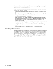
... other metal surface. When you add an option, do so. Movement can attach external options, such as external speakers, a printer, or a scanner. Handle adapters and memory modules by the edges. v Do not place the option on the computer cover or other unpainted metal surface on the computer for the option. 16...
... other metal surface. When you add an option, do so. Movement can attach external options, such as external speakers, a printer, or a scanner. Handle adapters and memory modules by the edges. v Do not place the option on the computer cover or other unpainted metal surface on the computer for the option. 16...
User Manual
Page 39
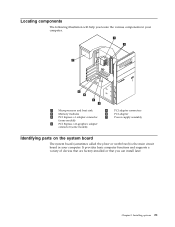
... computer functions and supports a variety of devices that are factory-installed or that you locate the various components in your computer. 1 Microprocessor and heat sink 2 Memory modules 3 PCI Express x1 adapter connector (some models) 4 PCI Express x16 graphics adapter connector (some models) 5 PCI adapter connectors 6 PCI adapter 7 Power supply assembly Identifying...
... computer functions and supports a variety of devices that are factory-installed or that you locate the various components in your computer. 1 Microprocessor and heat sink 2 Memory modules 3 PCI Express x1 adapter connector (some models) 4 PCI Express x16 graphics adapter connector (some models) 5 PCI adapter connectors 6 PCI adapter 7 Power supply assembly Identifying...
User Manual
Page 40
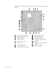
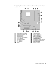
The following illustration shows the locations of parts on the system board (some models). 1 Microprocessor and heat sink 2 Microprocessor fan connector 3 Memory connector 1 4 Memory connector 2 5 Power connector 6 Diskette drive connector 7 IDE connector 8 SATA IDE connector (2) 9 Front panel connector 10 Clear CMOS/Recovery jumper 11 Front USB connectors (2) 12 Serial (...
The following illustration shows the locations of parts on the system board (some models). 1 Microprocessor and heat sink 2 Microprocessor fan connector 3 Memory connector 1 4 Memory connector 2 5 Power connector 6 Diskette drive connector 7 IDE connector 8 SATA IDE connector (2) 9 Front panel connector 10 Clear CMOS/Recovery jumper 11 Front USB connectors (2) 12 Serial (...
User Manual
Page 41
The following illustration shows the locations of parts on the system board (some models). 1 Microprocessor fan connector 2 Microprocessor and heat sink 3 Memory connector 1 4 Memory connector 2 5 Clear CMOS/Recovery jumper 6 Power connector 7 Diskette drive connector 8 IDE connector 1 9 IDE connector 2 10 Battery 11 Front panel connector 12 SATA IDE connectors (2) 13 ...
The following illustration shows the locations of parts on the system board (some models). 1 Microprocessor fan connector 2 Microprocessor and heat sink 3 Memory connector 1 4 Memory connector 2 5 Clear CMOS/Recovery jumper 6 Power connector 7 Diskette drive connector 8 IDE connector 1 9 IDE connector 2 10 Battery 11 Front panel connector 12 SATA IDE connectors (2) 13 ...
User Manual
Page 42
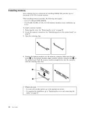
...the appropriate section. See "Removing the cover" on page 21. 3. v Use 256 MB, 512 MB, 1.0 GB or 2.0 GB memory modules in any combinatio up to a maximum of 4.0 GB of system memory. What to do next: v To work with the connector key 2 on the system board. Removing the cover. Installing... memory Your computer has two connectors for installing DIMMs that the notch 1 on the memory module aligns correctly with another option, go to "Replacing the cover and connecting the cables" on page 37...
...the appropriate section. See "Removing the cover" on page 21. 3. v Use 256 MB, 512 MB, 1.0 GB or 2.0 GB memory modules in any combinatio up to a maximum of 4.0 GB of system memory. What to do next: v To work with the connector key 2 on the system board. Removing the cover. Installing... memory Your computer has two connectors for installing DIMMs that the notch 1 on the memory module aligns correctly with another option, go to "Replacing the cover and connecting the cables" on page 37...
User Manual
Page 52
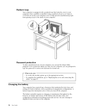
... next v To work with a padlock loop that maintains the date, time, and settings for normal use. Changing the battery Your computer has a special type of memory that locks the cover to your computer. however, no charging or maintenance throughout its life; Padlock loop Your computer is equipped with another option, go...
... next v To work with a padlock loop that maintains the date, time, and settings for normal use. Changing the battery Your computer has a special type of memory that locks the cover to your computer. however, no charging or maintenance throughout its life; Padlock loop Your computer is equipped with another option, go...
User Manual
Page 65
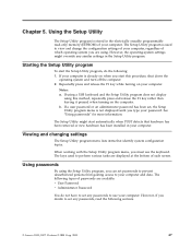
... program, you must use your computer and data. The Setup Utility might override any passwords, read -only memory (EEPROM) of passwords are available: v User Password v Administrator Password You do the following sections. © Lenovo 2005, 2007. When working with the Setup Utility program menu, you can set any passwords to your computer...
... program, you must use your computer and data. The Setup Utility might override any passwords, read -only memory (EEPROM) of passwords are available: v User Password v Administrator Password You do the following sections. © Lenovo 2005, 2007. When working with the Setup Utility program menu, you can set any passwords to your computer...
User Manual
Page 69
Chapter 6. Your computer system board has a module called electrically erasable programmable read-only memory (EEPROM, also referred to as downloadable files on the Lenovo Web site at http://www.lenovo.com/support on again. For most models, you can download either an update program to support systems.../BIOS update failure. Updating system programs This chapter contains information about updating POST/BIOS and how to complete the update. © Lenovo 2005, 2007. Using system programs System programs are available in a .txt file that the computer hardware can use the Setup Utility...
Chapter 6. Your computer system board has a module called electrically erasable programmable read-only memory (EEPROM, also referred to as downloadable files on the Lenovo Web site at http://www.lenovo.com/support on again. For most models, you can download either an update program to support systems.../BIOS update failure. Updating system programs This chapter contains information about updating POST/BIOS and how to complete the update. © Lenovo 2005, 2007. Using system programs System programs are available in a .txt file that the computer hardware can use the Setup Utility...

User Manual
Page 83
... four telephone numbers (n=0-3) stored in Command Mode. Commands are not echoed Commands are accepted by the modem while it is in the modem non-volatile memory. Appendix A. DS=n E_ E0 E1 +++ H_ H0 Function Manually answer incoming call. Commands are echoed Escape Characters - Basic AT commands Command A A/ D_ L P T W , @ ! ; Switch from a PC... your modem. Manual modem commands This appendix provides commands for Australia, New Zealand, Norway, and South Africa. Command) Force modem on-hook (hang up) © Lenovo 2005, 2007.
... four telephone numbers (n=0-3) stored in Command Mode. Commands are not echoed Commands are accepted by the modem while it is in the modem non-volatile memory. Appendix A. DS=n E_ E0 E1 +++ H_ H0 Function Manually answer incoming call. Commands are echoed Escape Characters - Basic AT commands Command A A/ D_ L P T W , @ ! ; Switch from a PC... your modem. Manual modem commands This appendix provides commands for Australia, New Zealand, Norway, and South Africa. Command) Force modem on-hook (hang up) © Lenovo 2005, 2007.
User Manual
Page 84
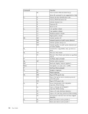
... Guide Function Force modem off-hook (make busy) Note: H1 command is not supported for Italy Display product-identification code Factory ROM checksum test Internal memory test Firmware ID Reserved ID Low speaker volume Low speaker volume Medium speaker volume High speaker volume Internal speaker off Internal speaker on until carrier...
... Guide Function Force modem off-hook (make busy) Note: H1 command is not supported for Italy Display product-identification code Factory ROM checksum test Internal memory test Firmware ID Reserved ID Low speaker volume Low speaker volume Medium speaker volume High speaker volume Internal speaker off Internal speaker on until carrier...
User Manual
Page 93
... system 10 software 9 installing options adapters 25 internal drives 29 memory 24 memory modules 24 security features 33 K keyboard connector 18, 19 L Lenovo Care 61 Lenovo Web site 62 locating components 21 M manual modem commands 65 memory dual inline memory modules (DIMMs) 24 installing 24 system 24 memory modules, installing 24 microphone connector 18, 19 modem commands... diagnostic CD image creating 55 running 56 diagnostic diskettes creating 56 running 56 drives bays 13, 27 CD 14 DVD 14 hard disk 14 © Lenovo 2005, 2007.
... system 10 software 9 installing options adapters 25 internal drives 29 memory 24 memory modules 24 security features 33 K keyboard connector 18, 19 L Lenovo Care 61 Lenovo Web site 62 locating components 21 M manual modem commands 65 memory dual inline memory modules (DIMMs) 24 installing 24 system 24 memory modules, installing 24 microphone connector 18, 19 modem commands... diagnostic CD image creating 55 running 56 diagnostic diskettes creating 56 running 56 drives bays 13, 27 CD 14 DVD 14 hard disk 14 © Lenovo 2005, 2007.
User Manual
Page 94
... 49 temporary startup device 49 serial connector 18, 19 Setup Utility 47 software installing 9 system board connectors 22, 23 identifying parts 21 location 22, 23 memory 14, 22, 23, 24 76 User Guide system programs 51 T trademarks 74 troubleshooting 53 U updating (flashing) BIOS 51 antivirus software 10 operating system 10 updating...
... 49 temporary startup device 49 serial connector 18, 19 Setup Utility 47 software installing 9 system board connectors 22, 23 identifying parts 21 location 22, 23 memory 14, 22, 23, 24 76 User Guide system programs 51 T trademarks 74 troubleshooting 53 U updating (flashing) BIOS 51 antivirus software 10 operating system 10 updating...


