Brochure
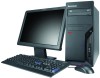
Page 3
... graphic cards are DirectX10 compliant All models are able to support DID via ADD2 card Limited warranty4 Up to 4 years Included software (preloaded in , Line- Lenovo recommends Windows Vista® Business. out and Microphone Desktop: 10 USB Ports (2 Front/6 Rear/2 Internal),1 Parallel/ 1 Serial/Audio/2 PS2/E-SATA port as optional, 2 LP PCI expansion slots,1 LP PCI-e 1x and1 LP PCI-e 16x, 2 Front audio ports: Headphone and Microphone, 3 Rear audio ports: Line-in, Line-out and Microphone SFF: 10 USB Ports (2 Front/6 Rear/2 Internal...
... graphic cards are DirectX10 compliant All models are able to support DID via ADD2 card Limited warranty4 Up to 4 years Included software (preloaded in , Line- Lenovo recommends Windows Vista® Business. out and Microphone Desktop: 10 USB Ports (2 Front/6 Rear/2 Internal),1 Parallel/ 1 Serial/Audio/2 PS2/E-SATA port as optional, 2 LP PCI expansion slots,1 LP PCI-e 1x and1 LP PCI-e 16x, 2 Front audio ports: Headphone and Microphone, 3 Rear audio ports: Line-in, Line-out and Microphone SFF: 10 USB Ports (2 Front/6 Rear/2 Internal...

Brochure
Page 4
... and is service partition. [Maximum capacity may not include user manuals or all countries. Microsoft, Windows and Vista are trademarks of memory intensive applications such as steaming video, graphics and CAD programs. Kensington MicroSaver Security Cable Lock from its retail version (if available) and may require the replacement of installed component with a 7-inch diameter lock barrel. Lenovo recommends Windows Vista® Business. Lenovo Laser Mouse (41U3074) Utilizes optical tracking...
... and is service partition. [Maximum capacity may not include user manuals or all countries. Microsoft, Windows and Vista are trademarks of memory intensive applications such as steaming video, graphics and CAD programs. Kensington MicroSaver Security Cable Lock from its retail version (if available) and may require the replacement of installed component with a 7-inch diameter lock barrel. Lenovo recommends Windows Vista® Business. Lenovo Laser Mouse (41U3074) Utilizes optical tracking...
User Manual
Page 5
... . . . . 81 Locating components 82 System board locations 83 Opening the cover 84 Replacing the CMOS battery 85 Replacing the microprocessor 86 Replacing the system board 89 Replacing a hard disk drive 90 Replacing an optical drive 92 Replacing a memory module 94 Replacing the modem 95 Replacing the Express card assembly 97 Replacing the Media Card Reader 98 Replacing the system fan assembly 100 Completing the FRU replacement 102 Chapter 9. FRU lists 105 Machine Type 6393 105 Machine Type 6394 115 Machine Type 6395 125 Machine Type 6396 140 Machine Type 6397 150...
... . . . . 81 Locating components 82 System board locations 83 Opening the cover 84 Replacing the CMOS battery 85 Replacing the microprocessor 86 Replacing the system board 89 Replacing a hard disk drive 90 Replacing an optical drive 92 Replacing a memory module 94 Replacing the modem 95 Replacing the Express card assembly 97 Replacing the Media Card Reader 98 Replacing the system fan assembly 100 Completing the FRU replacement 102 Chapter 9. FRU lists 105 Machine Type 6393 105 Machine Type 6394 115 Machine Type 6395 125 Machine Type 6396 140 Machine Type 6397 150...
User Manual
Page 45
.... See "Running diagnostics from the CD or diskettes" on the computer. v If the LED is not illuminated (off the computer and all display controls to help troubleshoot. 1. A down-level BIOS might have been rearranged or the drive startup sequence changed. Power-off ), go to the next step 3 on page 45. Set all external devices. 2. v Look for displayed error codes v Listen for beep codes v Look for readable instructions or a main menu on...
.... See "Running diagnostics from the CD or diskettes" on the computer. v If the LED is not illuminated (off the computer and all display controls to help troubleshoot. 1. A down-level BIOS might have been rearranged or the drive startup sequence changed. Power-off ), go to the next step 3 on page 45. Set all external devices. 2. v Look for displayed error codes v Listen for beep codes v Look for readable instructions or a main menu on...
User Manual
Page 46
... Diagnostic Diskettes (version) 7. Check the Power switch/LED assembly connector on page 81. 8. v Machine type and model v Processor or hard disk upgrades v Failure symptom - 3. Replace the AC/DC power adapter. 7. Replace the system board. Has this the original reported failure? Type and version level v Hardware configuration - BIOS level v Operating system software - Are the exact machine type and models 2. Have the same software versions and levels 6. Have the same setup for the operating system control files 40 Hardware Maintenance Manual See "Connectors on the rear...
... Diagnostic Diskettes (version) 7. Check the Power switch/LED assembly connector on page 81. 8. v Machine type and model v Processor or hard disk upgrades v Failure symptom - 3. Replace the AC/DC power adapter. 7. Replace the system board. Has this the original reported failure? Type and version level v Hardware configuration - BIOS level v Operating system software - Are the exact machine type and models 2. Have the same software versions and levels 6. Have the same setup for the operating system control files 40 Hardware Maintenance Manual See "Connectors on the rear...

User Manual
Page 56
...: A password can type either password. Note: Not all CDs, hard disks, and diskettes are using a USB keyboard and the Startup Device Menu does not display using this procedure to startup from changing configuration settings. Press and hold the F12 key then turn on page 49. 1. Setting, changing, and deleting a password To set, change, or delete a password, do the following procedures to set an Administrator Password. Turn off the computer. 2. Select the desired startup device from the Startup Device Menu and press Enter to access the Setup Utility...
...: A password can type either password. Note: Not all CDs, hard disks, and diskettes are using a USB keyboard and the Startup Device Menu does not display using this procedure to startup from changing configuration settings. Press and hold the F12 key then turn on page 49. 1. Setting, changing, and deleting a password To set, change, or delete a password, do the following procedures to set an Administrator Password. Turn off the computer. 2. Select the desired startup device from the Startup Device Menu and press Enter to access the Setup Utility...
User Manual
Page 66
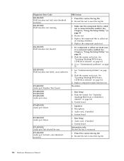
See Chapter 6, "Using the Setup Utility," on page 78 005-199-XXX Video test failed, cause unknown 1. Go to "Undetermined problems" on page 162 3. Go to "Undetermined problems" on page 49 2. Replace component under function test 006-25X-XXX Diskette interface Error 1. Video card, if installed 2. Diskette drive Cable 2. If a component is called out, make sure it is connected and/or enabled. See "Updating (flashing) BIOS from a CD-ROM or diskette" on page...
See Chapter 6, "Using the Setup Utility," on page 78 005-199-XXX Video test failed, cause unknown 1. Go to "Undetermined problems" on page 162 3. Go to "Undetermined problems" on page 49 2. Replace component under function test 006-25X-XXX Diskette interface Error 1. Video card, if installed 2. Diskette drive Cable 2. If a component is called out, make sure it is connected and/or enabled. See "Updating (flashing) BIOS from a CD-ROM or diskette" on page...

User Manual
Page 67
... "Updating (flashing) BIOS from a CD-ROM or diskette" on page 162 3. System board 1. Re-run test 3. Diagnostic Error Code 015-000-XXX USB port Interface Test Passed 015-001-XXX USB port Presence 015-002-XXX USB port Timeout 015-015-XXX USB port External Loopback failure 015-027-XXX USB port Configuration/Setup error 015-032-XXX USB port Device Controller failure 015-034-XXX USB port buffer allocation failure 015-035-XXX USB port Reset condition detected 015-036-XXX USB port Register error 015-040-XXX USB port IRQ failure...
... "Updating (flashing) BIOS from a CD-ROM or diskette" on page 162 3. System board 1. Re-run test 3. Diagnostic Error Code 015-000-XXX USB port Interface Test Passed 015-001-XXX USB port Presence 015-002-XXX USB port Timeout 015-015-XXX USB port External Loopback failure 015-027-XXX USB port Configuration/Setup error 015-032-XXX USB port Device Controller failure 015-034-XXX USB port buffer allocation failure 015-035-XXX USB port Reset condition detected 015-036-XXX USB port Register error 015-040-XXX USB port IRQ failure...
User Manual
Page 68
... PCI Card Failure 1. Go to "Undetermined problems" on page 78 2. Go to "Undetermined problems" on page 78 015-199-XXX USB port test failed, cause unknown 1. See "Updating (flashing) BIOS from a CD-ROM or diskette" on page 162 3. System board 018-195-XXX PCI Card Test aborted by user 1. Replace component under function test 62 Hardware Maintenance Manual Replace the component under test 018-198-XXX PCI Card test aborted 1. Diagnostic Error Code FRU/Action 015-198-XXX USB port test aborted 1. Re-run test 3. Replace...
... PCI Card Failure 1. Go to "Undetermined problems" on page 78 2. Go to "Undetermined problems" on page 78 015-199-XXX USB port test failed, cause unknown 1. See "Updating (flashing) BIOS from a CD-ROM or diskette" on page 162 3. System board 018-195-XXX PCI Card Test aborted by user 1. Replace component under function test 62 Hardware Maintenance Manual Replace the component under test 018-198-XXX PCI Card test aborted 1. Diagnostic Error Code FRU/Action 015-198-XXX USB port test aborted 1. Re-run test 3. Replace...
User Manual
Page 69
... cable 2. Check power supply voltages 3. System board Chapter 7. Press F3 to "Undetermined problems" on page 78 1. Riser card, if installed 3. Riser card, if installed 3. PCI card 2. PCI card 2. Make sure the component that is called out, make sure it is called out in warning statement 4. Go to review the log file 2. See Chapter 6, "Using the Setup Utility," on page 162 3. Replace the component under function test 1. Symptom-to-FRU Index 63 Diagnostic Error Code...
... cable 2. Check power supply voltages 3. System board Chapter 7. Press F3 to "Undetermined problems" on page 78 1. Riser card, if installed 3. Riser card, if installed 3. PCI card 2. PCI card 2. Make sure the component that is called out, make sure it is called out in warning statement 4. Go to review the log file 2. See Chapter 6, "Using the Setup Utility," on page 162 3. Replace the component under function test 1. Symptom-to-FRU Index 63 Diagnostic Error Code...

User Manual
Page 70
... page 162 3. IDE device 5. Re-run test 3. See Chapter 6, "Using the Setup Utility," on page 162 3. See "Updating (flashing) BIOS from a CD-ROM or diskette" on page 78 1. Go to review the log file 2. Replace component under test 1. Check AC/DC power adapter 3. System board 64 Hardware Maintenance Manual Reseat IDE signal cable 4. Check AC/DC power adapter 3. Reseat IDE signal cable 4. System board Information only Re-start the test to "Undetermined problems" on page 49 2. Press...
... page 162 3. IDE device 5. Re-run test 3. See Chapter 6, "Using the Setup Utility," on page 162 3. See "Updating (flashing) BIOS from a CD-ROM or diskette" on page 78 1. Go to review the log file 2. Replace component under test 1. Check AC/DC power adapter 3. System board 64 Hardware Maintenance Manual Reseat IDE signal cable 4. Check AC/DC power adapter 3. Reseat IDE signal cable 4. System board Information only Re-start the test to "Undetermined problems" on page 49 2. Press...

User Manual
Page 71
... adapter card, if installed 5. Check AC/DC power adapter 3. SCSI device 4. Re-run test 3. Flash the system and re-test. Go to "Undetermined problems" on page 49 2. Symptom-to review the log file 2. SCSI device 4. Replace the component that is called out is connected and/or enabled. RAID signal cable 2. RAID device 3. Re-start the test, if necessary Chapter 7. See Chapter 6, "Using the Setup Utility," on page 78 2. See Chapter 6, "Using the Setup Utility," on page 162 3. System board...
... adapter card, if installed 5. Check AC/DC power adapter 3. SCSI device 4. Re-run test 3. Flash the system and re-test. Go to "Undetermined problems" on page 49 2. Symptom-to review the log file 2. SCSI device 4. Replace the component that is called out is connected and/or enabled. RAID signal cable 2. RAID device 3. Re-start the test, if necessary Chapter 7. See Chapter 6, "Using the Setup Utility," on page 78 2. See Chapter 6, "Using the Setup Utility," on page 162 3. System board...
User Manual
Page 72
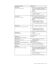
... board 1. Make sure the component that is connected and/or enabled. Microphone 3. Replace the component under function test No action 1. System board Information only Re-start the test to review the log file 2. See "Undetermined problems" on page 49 2. Re-run test 3. See Chapter 6, "Using the Setup Utility," on page 78 2. Flash the system. Audio card, if installed 3. Flash the system and re-test. Speakers 2. See "Updating (flashing) BIOS from a CD-ROM or diskette" on page 162 3. Audio card...
... board 1. Make sure the component that is connected and/or enabled. Microphone 3. Replace the component under function test No action 1. System board Information only Re-start the test to review the log file 2. See "Undetermined problems" on page 49 2. Re-run test 3. See Chapter 6, "Using the Setup Utility," on page 78 2. Flash the system. Audio card, if installed 3. Flash the system and re-test. Speakers 2. See "Updating (flashing) BIOS from a CD-ROM or diskette" on page 162 3. Audio card...
User Manual
Page 73
... is called out, make sure it is connected and/or enabled. Replace the component under test Chapter 7. See "Updating (flashing) BIOS from a CD-ROM or diskette" on page 162 3. See "Updating (flashing) BIOS from a CD-ROM or diskette" on page 162 3. Diagnostic Error Code FRU/Action 071-197-XXX Audio port test warning 1. Replace the component that is connected and/or enabled. See Chapter 6, "Using the Setup Utility," on page 49 2. Audio card, if installed 3. Replace the component that...
... is called out, make sure it is connected and/or enabled. Replace the component under test Chapter 7. See "Updating (flashing) BIOS from a CD-ROM or diskette" on page 162 3. See "Updating (flashing) BIOS from a CD-ROM or diskette" on page 162 3. Diagnostic Error Code FRU/Action 071-197-XXX Audio port test warning 1. Replace the component that is connected and/or enabled. See Chapter 6, "Using the Setup Utility," on page 49 2. Audio card, if installed 3. Replace the component that...

User Manual
Page 74
...-start the test to review the log file 2. Make sure the component that is connected and/or enabled. If a component is called out, make sure it is connected and/or enabled. Diagnostic Error Code 080-198-XXX Game Port interface test aborted 080-199-XXX Game Port interface test failed, cause unknown 086-000-XXX Mouse Port interface Test Passed 086-001-XXX Mouse Port interface Presence 086-032-XXX Mouse Port interface Device controller failure...
...-start the test to review the log file 2. Make sure the component that is connected and/or enabled. If a component is called out, make sure it is connected and/or enabled. Diagnostic Error Code 080-198-XXX Game Port interface test aborted 080-199-XXX Game Port interface test failed, cause unknown 086-000-XXX Mouse Port interface Test Passed 086-001-XXX Mouse Port interface Presence 086-032-XXX Mouse Port interface Device controller failure...
User Manual
Page 76
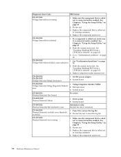
... test 70 Hardware Maintenance Manual Flash the system and re-test. See "Updating (flashing) BIOS from a CD-ROM or diskette" on page 162 3. See "Updating (flashing) BIOS from a CD-ROM or diskette" on page 78 170-199-XXX Voltage Sensor(s) test failed, cause unknown 1. AC/DC power adapter 2. Re-run test 3. Replace the component that is called out in warning statement 4. Replace the component under test 170-198-XXX Voltage Sensor(s) test aborted 1. Diagnostic Error Code...
... test 70 Hardware Maintenance Manual Flash the system and re-test. See "Updating (flashing) BIOS from a CD-ROM or diskette" on page 162 3. See "Updating (flashing) BIOS from a CD-ROM or diskette" on page 78 170-199-XXX Voltage Sensor(s) test failed, cause unknown 1. AC/DC power adapter 2. Re-run test 3. Replace the component that is called out in warning statement 4. Replace the component under test 170-198-XXX Voltage Sensor(s) test aborted 1. Diagnostic Error Code...
User Manual
Page 81
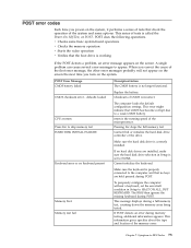
... drive. Symptom-to appear. This series of the system and some basic system-board operations v Checks the memory operation v Starts the video operation v Verifies that the boot drive is properly connected to the computer and that CMOS has become corrupt due to skip memory test HARD DISK INSTALL FAILURE The computer loads the default configuration settings. Keyboard error or no keyboard present If no hard disk drives are held pressed during memory testing, additional information appears. Cannot initialize the keyboard. The BIOS...
... drive. Symptom-to appear. This series of the system and some basic system-board operations v Checks the memory operation v Starts the video operation v Verifies that the boot drive is properly connected to the computer and that CMOS has become corrupt due to skip memory test HARD DISK INSTALL FAILURE The computer loads the default configuration settings. Keyboard error or no keyboard present If no hard disk drives are held pressed during memory testing, additional information appears. Cannot initialize the keyboard. The BIOS...

User Manual
Page 83
... Hard Disk Drive 3. System Board 2. Power Switch 2. System Board 2. Hard Disk Drive Cable Incorrect memory size during POST 1. Diskette Drive Cable 3. Network Adapter Intensity or color varies from server 1. Memory Module 3. Diskette Drive 2. System Board No power or fan not running 1. Chapter 7. Symptom-to network adapter 2. Riser card, if installed Computer will not perform a Wake On LAN® (if applicable) 1. Video adapter (if present) 3. Ensure that network is using correct MAC address 5. Check power supply and signal cable connections...
... Hard Disk Drive 3. System Board 2. Power Switch 2. System Board 2. Hard Disk Drive Cable Incorrect memory size during POST 1. Diskette Drive Cable 3. Network Adapter Intensity or color varies from server 1. Memory Module 3. Diskette Drive 2. System Board No power or fan not running 1. Chapter 7. Symptom-to network adapter 2. Riser card, if installed Computer will not perform a Wake On LAN® (if applicable) 1. Video adapter (if present) 3. Ensure that network is using correct MAC address 5. Check power supply and signal cable connections...
User Manual
Page 84
... the network adapter LED status Some or all devices and adapters have been removed, and the problem continues, replace the system board. 78 Hardware Maintenance Manual Memory modules d. External Cache RAM g. Diskette Drive Cable Other display symptoms not listed above (including blank or illegible display) 1. System Board 5. Remove or disconnect the following components (if installed) one at a time. a. External devices (modem, printer, or mouse) b. Any adapters c. Message/Symptom FRU/Action Non-system disk or disk error-type message with a known-good diagnostics...
... the network adapter LED status Some or all devices and adapters have been removed, and the problem continues, replace the system board. 78 Hardware Maintenance Manual Memory modules d. External Cache RAM g. Diskette Drive Cable Other display symptoms not listed above (including blank or illegible display) 1. System Board 5. Remove or disconnect the following components (if installed) one at a time. a. External devices (modem, printer, or mouse) b. Any adapters c. Message/Symptom FRU/Action Non-system disk or disk error-type message with a known-good diagnostics...

User Manual
Page 167
... of BIOS. BIOS levels An incorrect level of BIOS: - Use the following : v Passwords v Vital Product Data v Management Information Format (MIF) Hardware controlled Passwords Hardware controlled passwords are set using the Setup Utility program. v Sources for the computer, and where to the computer by the computer. Lenovo Customer Support Center 3. v To determine the current Level of BIOS can cause false errors and unnecessary FRU replacement. After you replace the system board, the VPD must be updated. Lenovo support...
... of BIOS. BIOS levels An incorrect level of BIOS: - Use the following : v Passwords v Vital Product Data v Management Information Format (MIF) Hardware controlled Passwords Hardware controlled passwords are set using the Setup Utility program. v Sources for the computer, and where to the computer by the computer. Lenovo Customer Support Center 3. v To determine the current Level of BIOS can cause false errors and unnecessary FRU replacement. After you replace the system board, the VPD must be updated. Lenovo support...


