Lenovo Lenovo Thinkpad Sl510 28479UU
Related Manual Pages


Similar Questions

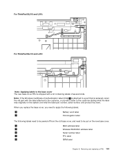
Wireless Antenna Of Thinkpad Laptop L512
There are 4 wireless antenna cables from the screen on a thinkpad laptop L512. How do I connect them
There are 4 wireless antenna cables from the screen on a thinkpad laptop L512. How do I connect them
(Posted by shubertmagawa04 1 year ago)

Lenovo Thinkpad X100e Not Installed Windows 10
Hello, could you help me install windows 10 on my lenovo thinkpad X100e with 4gb of ram and 250gb of...
Hello, could you help me install windows 10 on my lenovo thinkpad X100e with 4gb of ram and 250gb of...
(Posted by virgynet 2 years ago)

Lenovo Thinkpad L412 Wifi Connectivity Issue
Hi I cannot connect Wifi in my Lenovo Thinkpad L412. Please help how to solve this issue. Ved.
Hi I cannot connect Wifi in my Lenovo Thinkpad L412. Please help how to solve this issue. Ved.
(Posted by vedapr 9 years ago)