User Manual
Page 5
... battery 21 Replacing the power supply assembly . . . . 23 Replacing the heat sink and fan assembly . . . 25 Replacing the microprocessor 27 Replacing the optical drive 30 Replacing the hard disk drive 31 Replacing the front audio and USB assembly . . 34 Replacing the rear fan assembly 35 Replacing the USB keyboard or mouse . . . . 36 Completing the parts replacement 37 Obtaining device drivers 38 Basic security features 38 Integrated cable lock 39 Padlock 40 Password protection 40 Erasing a lost or forgotten password (clearing CMOS 40 Chapter 3. Recovery...
... battery 21 Replacing the power supply assembly . . . . 23 Replacing the heat sink and fan assembly . . . 25 Replacing the microprocessor 27 Replacing the optical drive 30 Replacing the hard disk drive 31 Replacing the front audio and USB assembly . . 34 Replacing the rear fan assembly 35 Replacing the USB keyboard or mouse . . . . 36 Completing the parts replacement 37 Obtaining device drivers 38 Basic security features 38 Integrated cable lock 39 Padlock 40 Password protection 40 Erasing a lost or forgotten password (clearing CMOS 40 Chapter 3. Recovery...
User Manual
Page 9
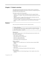
...DDR3 DIMMs) Internal drives v Card reader (available in some models) v Optical drive v Serial Advanced Technology Attachment (SATA) hard disk drive Video subsystem v Integrated graphics card functioning through a Video Graphics Array (VGA) connector © Copyright Lenovo 2010 1 System information The following information covers a variety of the following topics: v "Features": This section provides information about the software programs provided with one of models. v "Specifications" on the system board, and internal drives. See Chapter 4, "Using the Setup Utility program...
...DDR3 DIMMs) Internal drives v Card reader (available in some models) v Optical drive v Serial Advanced Technology Attachment (SATA) hard disk drive Video subsystem v Integrated graphics card functioning through a Video Graphics Array (VGA) connector © Copyright Lenovo 2010 1 System information The following information covers a variety of the following topics: v "Features": This section provides information about the software programs provided with one of models. v "Specifications" on the system board, and internal drives. See Chapter 4, "Using the Setup Utility program...

User Manual
Page 10
...-in connector, audio line-out connector, and microphone connector on the rear panel Connectivity v 10/100/1000 Mbps integrated Ethernet controller System management features v Ability to store the power-on self-test (POST) hardware test results v Advanced Configuration and Power Interface (ACPI) v Automatic power-on startup v Desktop Management Interface (DMI) v Intel Trusted Execution Technology (Intel TXT) v Preboot Execution Environment (PXE) v System Management (SM) Basic Input/Output System (BIOS) and SM software v Wake on LAN (WOL) v Windows Management...
...-in connector, audio line-out connector, and microphone connector on the rear panel Connectivity v 10/100/1000 Mbps integrated Ethernet controller System management features v Ability to store the power-on self-test (POST) hardware test results v Advanced Configuration and Power Interface (ACPI) v Automatic power-on startup v Desktop Management Interface (DMI) v Intel Trusted Execution Technology (Intel TXT) v Preboot Execution Environment (PXE) v System Management (SM) Basic Input/Output System (BIOS) and SM software v Wake on LAN (WOL) v Windows Management...
User Manual
Page 13
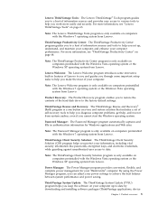
... guarding against unauthorized user access to the factory default settings. Note: The Lenovo ThinkVantage Tools program is only available on page 64. Product Recovery: The Product Recovery program enables you set up, understand, and maintain your computer, and enhance your computer up-to help , and recover from Lenovo. ThinkVantage Productivity Center: The ThinkVantage Productivity Center program guides you cannot start the Windows operating system. Power Manager: The Power Manager program provides...
... guarding against unauthorized user access to the factory default settings. Note: The Lenovo ThinkVantage Tools program is only available on page 64. Product Recovery: The Product Recovery program enables you set up, understand, and maintain your computer, and enhance your computer up-to help , and recover from Lenovo. ThinkVantage Productivity Center: The ThinkVantage Productivity Center program guides you cannot start the Windows operating system. Power Manager: The Power Manager program provides...

User Manual
Page 16
...-coded to help you determine where to connect the cables on your computer. Figure 2. Rear connector and part locations 1 Voltage-selection switch (available on some models) 2 Power cord connector 3 Serial port 4 VGA monitor connector 5 USB connectors (4) 6 Microphone connector 7 Audio line-out connector 8 Audio line-in connector 9 PCI Express x16 graphics card slot 10 PCI Express x1 card slot 11 PCI card slots (2) 12 Serial port (available on some models) 13 Ethernet connector 14 Personal System/2® (PS/2®) keyboard and mouse connector (available on some models) 8 User Guide...
...-coded to help you determine where to connect the cables on your computer. Figure 2. Rear connector and part locations 1 Voltage-selection switch (available on some models) 2 Power cord connector 3 Serial port 4 VGA monitor connector 5 USB connectors (4) 6 Microphone connector 7 Audio line-out connector 8 Audio line-in connector 9 PCI Express x16 graphics card slot 10 PCI Express x1 card slot 11 PCI card slots (2) 12 Serial port (available on some models) 13 Ethernet connector 14 Personal System/2® (PS/2®) keyboard and mouse connector (available on some models) 8 User Guide...

User Manual
Page 17
...as powered stereo speakers (speakers with built-in amplifiers), headphones, multimedia keyboards, the audio line-in connector on some models) connector. Audio line-out connector Used to attach a device that use a Category 5 Ethernet cable. Product overview 9 Note: To operate the computer within FCC Class B limits, use a VGA monitor connector. USB connector Used to send audio signals from an external audio device, such as a USB keyboard, a USB mouse, a USB scanner, or a USB printer. Microphone connector Used to attach a microphone to attach an external modem, a serial...
...as powered stereo speakers (speakers with built-in amplifiers), headphones, multimedia keyboards, the audio line-in connector on some models) connector. Audio line-out connector Used to attach a device that use a Category 5 Ethernet cable. Product overview 9 Note: To operate the computer within FCC Class B limits, use a VGA monitor connector. USB connector Used to send audio signals from an external audio device, such as a USB keyboard, a USB mouse, a USB scanner, or a USB printer. Microphone connector Used to attach a microphone to attach an external modem, a serial...

User Manual
Page 19
...Locating parts on the system board Figure 4 shows the locations of media. In this manual, the bays are installed in bays. Refer to the appropriate section in each bay and correctly connect the cables to as bay 1, bay 2, and so on the system board. Internal drives are referred to the drive installed. System board part locations 1 Microprocessor 2 Microprocessor fan connector 3 Memory slots (2) 4 Thermal sensor connector 5 24-pin power connector 6 Parallel connector 7 Battery 8 Cover presence switch connector (Intrusion switch connector) (some models) 9 SATA connectors (3) 10 Clear CMOS...
...Locating parts on the system board Figure 4 shows the locations of media. In this manual, the bays are installed in bays. Refer to the appropriate section in each bay and correctly connect the cables to as bay 1, bay 2, and so on the system board. Internal drives are referred to the drive installed. System board part locations 1 Microprocessor 2 Microprocessor fan connector 3 Memory slots (2) 4 Thermal sensor connector 5 24-pin power connector 6 Parallel connector 7 Battery 8 Cover presence switch connector (Intrusion switch connector) (some models) 9 SATA connectors (3) 10 Clear CMOS...

User Manual
Page 31
...://www.lenovo.com/support This section provides instructions on how to replace the power supply assembly. Hazardous voltage, current, and energy levels are present inside these parts, contact a service technician. To replace the power supply assembly, do the following label attached. See "Removing the computer cover" on a power supply or any part that has the following : 1. Note: You might also need to release the power supply assembly cables from the drives and turn...
...://www.lenovo.com/support This section provides instructions on how to replace the power supply assembly. Hazardous voltage, current, and energy levels are present inside these parts, contact a service technician. To replace the power supply assembly, do the following label attached. See "Removing the computer cover" on a power supply or any part that has the following : 1. Note: You might also need to release the power supply assembly cables from the drives and turn...

User Manual
Page 47
... an integrated cable lock from Lenovo by searching for Kensington at: http://www.lenovo.com/support Note: Make sure that the integrated cable lock you installed does not interfere with other non-permanent fixture. This is operated with many notebook computers. Figure 33. You can be used with a key. See Figure 33. Installing or replacing hardware 39 Integrated cable lock An integrated cable lock, sometimes...
... an integrated cable lock from Lenovo by searching for Kensington at: http://www.lenovo.com/support Note: Make sure that the integrated cable lock you installed does not interfere with other non-permanent fixture. This is operated with many notebook computers. Figure 33. You can be used with a key. See Figure 33. Installing or replacing hardware 39 Integrated cable lock An integrated cable lock, sometimes...

User Manual
Page 49
6. Reinstall any parts and reconnect any cables that have been removed or disconnected. 7. Turn on page 37. 8. Your password has been erased and you can use the Setup Utility program to the standard position (pin 1 and pin 2). 11. Then, turn off the computer by holding the power switch for approximately 10 seconds. Move the Clear CMOS /Recovery jumper back to set a new password. See "Completing the parts replacement" on the computer. Chapter 2. Turn on...
6. Reinstall any parts and reconnect any cables that have been removed or disconnected. 7. Turn on page 37. 8. Your password has been erased and you can use the Setup Utility program to the standard position (pin 1 and pin 2). 11. Then, turn off the computer by holding the power switch for approximately 10 seconds. Move the Clear CMOS /Recovery jumper back to set a new password. See "Completing the parts replacement" on the computer. Chapter 2. Turn on...

User Manual
Page 51
... factory default settings. Your Microsoft Windows license permits you to create only one data medium, so it is important that you store the recovery media in an operational state after you can use recovery media to restore the hard disk drive to create recovery media as early as possible. The recovery media might contain a boot medium and a data medium. Recovery information This chapter provides information about the recovery solutions provided by Lenovo...
... factory default settings. Your Microsoft Windows license permits you to create only one data medium, so it is important that you store the recovery media in an operational state after you can use recovery media to restore the hard disk drive to create recovery media as early as possible. The recovery media might contain a boot medium and a data medium. Recovery information This chapter provides information about the recovery solutions provided by Lenovo...

User Manual
Page 52
... the factory default settings. You can use recovery media on the hard disk drive will be given the option to put the computer in an operational state after all the files currently on the Windows 7 operating system or the Windows Vista operating system, do the following : 1. To use Product Recovery discs to restore your computer to the factory default settings, perform a custom factory recovery, or perform other USB storage device) to recover or reinstall your recovery media, connect the boot medium (memory key...
... the factory default settings. You can use recovery media on the hard disk drive will be given the option to put the computer in an operational state after all the files currently on the Windows 7 operating system or the Windows Vista operating system, do the following : 1. To use Product Recovery discs to restore your computer to the factory default settings, perform a custom factory recovery, or perform other USB storage device) to recover or reinstall your recovery media, connect the boot medium (memory key...

User Manual
Page 55
... key when turning on different operating systems. Chapter 3. The Rescue and Recovery workspace opens after using a rescue medium vary depending on the primary hard disk drive partition (usually drive C:) will be started in the recovery process. v To restore your hard disk drive from a Rescue and Recovery backup or to restore your hard disk drive to the factory default settings, click Restore your system and follow the instructions on your hard disk drive. See "Installing or reinstalling device drivers" on page 49. 4. Creating and using...
... key when turning on different operating systems. Chapter 3. The Rescue and Recovery workspace opens after using a rescue medium vary depending on the primary hard disk drive partition (usually drive C:) will be started in the recovery process. v To restore your hard disk drive from a Rescue and Recovery backup or to restore your hard disk drive to the factory default settings, click Restore your system and follow the instructions on your hard disk drive. See "Installing or reinstalling device drivers" on page 49. 4. Creating and using...

User Manual
Page 56
... using a disc, a USB hard disk drive, or a secondary internal hard disk drive. 5. The Rescue and Recovery program opens. 2. In the Rescue Media area, select the type of the rescue medium you to create a rescue medium. Click OK and follow the instructions on the screen to install a secondary hard disk drive. v If you have created. Turn off your computer. 2. On the Startup Device Menu, select the desired optical drive as the first boot device and press Enter. From the Windows desktop, click Start...
... using a disc, a USB hard disk drive, or a secondary internal hard disk drive. 5. The Rescue and Recovery program opens. 2. In the Rescue Media area, select the type of the rescue medium you to create a rescue medium. Click OK and follow the instructions on the screen to install a secondary hard disk drive. v If you have created. Turn off your computer. 2. On the Startup Device Menu, select the desired optical drive as the first boot device and press Enter. From the Windows desktop, click Start...
User Manual
Page 57
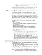
... to the factory default settings. If you need to restore the hard disk drive to install a secondary hard disk drive, see "Replacing the hard disk drive" on page 31. Turn on the screen to access the Rescue and Recovery workspace or the Windows environment, do the following: 1. This file might be named after the operating system, such as AUDIO or VIDEO. 5. Recovery information 49 Open the DRIVERS folder. Open the appropriate device subfolder. 6. Installing or reinstalling device drivers Before installing or reinstalling device drivers, make sure...
... to the factory default settings. If you need to restore the hard disk drive to install a secondary hard disk drive, see "Replacing the hard disk drive" on page 31. Turn on the screen to access the Rescue and Recovery workspace or the Windows environment, do the following: 1. This file might be named after the operating system, such as AUDIO or VIDEO. 5. Recovery information 49 Open the DRIVERS folder. Open the appropriate device subfolder. 6. Installing or reinstalling device drivers Before installing or reinstalling device drivers, make sure...
User Manual
Page 61
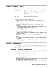
... key when turning on page 51. 2. Notes: a. Chapter 4. To enable or disable a device, do the following : 1. SATA Controller When this section to the SATA connectors (such as a hard disk drive or the disc in the system configuration. If you want to a device. From the Setup Utility program main menu, select Devices. 3. Select the desired startup device on the Startup Device Menu and press Enter. Using the Setup Utility program 53 You can use the instructions in this option is set up USB connectors. Enabling or disabling a device...
... key when turning on page 51. 2. Notes: a. Chapter 4. To enable or disable a device, do the following : 1. SATA Controller When this section to the SATA connectors (such as a hard disk drive or the disc in the system configuration. If you want to a device. From the Setup Utility program main menu, select Devices. 3. Select the desired startup device on the Startup Device Menu and press Enter. Using the Setup Utility program 53 You can use the instructions in this option is set up USB connectors. Enabling or disabling a device...

User Manual
Page 64
... the maintenance position (pin 2 and pin 3). 6. Click Downloads and drivers. Click the BIOS update link. 3. Click the TXT file that you do want to change the machine type and model, it is commonly called Boot-block Recovery. 1. See "Removing the computer cover" on page 11. 4. Reinstall the computer cover and reconnect the power cords for updating (flashing) the BIOS from your operating system. 4. After the update is completed, remove the disc from a POST and BIOS update failure...
... the maintenance position (pin 2 and pin 3). 6. Click Downloads and drivers. Click the BIOS update link. 3. Click the TXT file that you do want to change the machine type and model, it is commonly called Boot-block Recovery. 1. See "Removing the computer cover" on page 11. 4. Reinstall the computer cover and reconnect the power cords for updating (flashing) the BIOS from your operating system. 4. After the update is completed, remove the disc from a POST and BIOS update failure...

User Manual
Page 67
... is clean. Refer to the rear of service and support telephone numbers. v The USB mouse is correctly connected to "Cleaning an optical mouse" on . The USB keyboard or mouse does not work. v The monitor power cord is blank. v The monitor is turned on page 62. © Copyright Lenovo 2010 59 Verify that came with your computer has a PCI graphics card installed, be sure to use the monitor connector on the graphics card rather than the integrated one...
... is clean. Refer to the rear of service and support telephone numbers. v The USB mouse is correctly connected to "Cleaning an optical mouse" on . The USB keyboard or mouse does not work. v The monitor power cord is blank. v The monitor is turned on page 62. © Copyright Lenovo 2010 59 Verify that came with your computer has a PCI graphics card installed, be sure to use the monitor connector on the graphics card rather than the integrated one...

User Manual
Page 79
...-sensitive 13 diagnostic programs, troubleshooting 59 diagnostic programs, using 65 documentation, using 65 drivers, device 38 drives internal 11 E environment, operating 4 Ethernet 2 Ethernet connector 9 © Copyright Lenovo 2010 exiting, Setup Utility program 54 expansion 2 external options, installing 14 F failure, recovering from a POST and BIOS update 56 features 1 flashing the BIOS 55 front connectors, controls, indicators 7 front audio and USB assembly, replacing 34 front bezel removing, reinstalling 15 G getting help 63 information 63 service 63 H hard disk drive, replacing 31 heat...
...-sensitive 13 diagnostic programs, troubleshooting 59 diagnostic programs, using 65 documentation, using 65 drivers, device 38 drives internal 11 E environment, operating 4 Ethernet 2 Ethernet connector 9 © Copyright Lenovo 2010 exiting, Setup Utility program 54 expansion 2 external options, installing 14 F failure, recovering from a POST and BIOS update 56 features 1 flashing the BIOS 55 front connectors, controls, indicators 7 front audio and USB assembly, replacing 34 front bezel removing, reinstalling 15 G getting help 63 information 63 service 63 H hard disk drive, replacing 31 heat...

User Manual
Page 80
... Recovery 60 PCI card 17 installing, replacing 17 slots 17 PCI card latch 17 physical specifications 4 power supply features 3 power supply assembly replacing 23 power-on password 52 power-on self-test (POST) 55 programs, updating system 55 protection, password 40 purchasing additional services 67 R rear connectors 8 rear fan assembly, replacing 35 72 User Guide recovering from a POST and BIOS update failure 56 software 43 recovery Boot-block Recovery 56 operations, backup and 45 problems, solving 49 recovery media, creating and using 43 reinstalling device drivers 49 removing computer cover...
... Recovery 60 PCI card 17 installing, replacing 17 slots 17 PCI card latch 17 physical specifications 4 power supply features 3 power supply assembly replacing 23 power-on password 52 power-on self-test (POST) 55 programs, updating system 55 protection, password 40 purchasing additional services 67 R rear connectors 8 rear fan assembly, replacing 35 72 User Guide recovering from a POST and BIOS update failure 56 software 43 recovery Boot-block Recovery 56 operations, backup and 45 problems, solving 49 recovery media, creating and using 43 reinstalling device drivers 49 removing computer cover...


