Brochure
Page 1
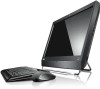
...auto-brightness control allows an extra energy savings of $0.103 k/Wh - Windows®. Lenovo® recommends Windows 7. ENHANCED EXPERIENCE THINKcentre m series LEnovo®ThinkCentre M90z, PREMIUM ENTERPRISE-LEVEL COMPUTING BUILT IN AN ALL-IN-ONE DESKTOP The ThinkCentre M90z All-In-One (AIO) ...desktop is the world's first AIO with the outstanding Lenovo Enhanced Experience for Windows® 7...
...auto-brightness control allows an extra energy savings of $0.103 k/Wh - Windows®. Lenovo® recommends Windows 7. ENHANCED EXPERIENCE THINKcentre m series LEnovo®ThinkCentre M90z, PREMIUM ENTERPRISE-LEVEL COMPUTING BUILT IN AN ALL-IN-ONE DESKTOP The ThinkCentre M90z All-In-One (AIO) ...desktop is the world's first AIO with the outstanding Lenovo Enhanced Experience for Windows® 7...
Brochure
Page 4
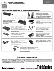
... inline microphone for clear communications Kensington Security Cable Lock by Lenovo (73P2582) Help reduce theft, increase physical asset security www.lenovo.com/support/security Gemplus 54mm ExpressCard Smart Card Reader from Lenovo (41N3043) Control access to databases, corporate computer networks www.lenovo.com/support/security Lenovo Laser Mouse (41U3074) High performance, fully programmable, superior comfort laser...
... inline microphone for clear communications Kensington Security Cable Lock by Lenovo (73P2582) Help reduce theft, increase physical asset security www.lenovo.com/support/security Gemplus 54mm ExpressCard Smart Card Reader from Lenovo (41N3043) Control access to databases, corporate computer networks www.lenovo.com/support/security Lenovo Laser Mouse (41U3074) High performance, fully programmable, superior comfort laser...

User Manual
Page 4
... delivered pursuant a General Services Administration "GSA" contract, use , reproduction and disclosure. GS-35F-05925. Second Edition (May 2011) © Copyright Lenovo 2011. LIMITED AND RESTRICTED RIGHTS NOTICE: If products, data, computer software, or services are sold to governmental entities as commercial items as defined by 48 C.F.R. 2.101 with limited and restricted rights...
... delivered pursuant a General Services Administration "GSA" contract, use , reproduction and disclosure. GS-35F-05925. Second Edition (May 2011) © Copyright Lenovo 2011. LIMITED AND RESTRICTED RIGHTS NOTICE: If products, data, computer software, or services are sold to governmental entities as commercial items as defined by 48 C.F.R. 2.101 with limited and restricted rights...

User Manual
Page 5
... 67 Updating (flashing) the BIOS from a disc . . . . 67 Updating (flashing) the BIOS from your Windows operating system 6 Locating computer controls, connectors, and parts 7 Front view 8 Rear view 9 Component locations 11 System board part and connector locations . 12 Chapter 2. Installing ...44 Replacing the rear I/O assembly 45 Replacing the right I/O assembly. . . . . . 46 Replacing the power supply 47 © Copyright Lenovo , 2011 Replacing the keyboard 49 Replacing the mouse 50 Completing the parts replacement . . . . . 52 Obtaining device drivers 53 Basic security features...
... 67 Updating (flashing) the BIOS from a disc . . . . 67 Updating (flashing) the BIOS from your Windows operating system 6 Locating computer controls, connectors, and parts 7 Front view 8 Rear view 9 Component locations 11 System board part and connector locations . 12 Chapter 2. Installing ...44 Replacing the rear I/O assembly 45 Replacing the right I/O assembly. . . . . . 46 Replacing the power supply 47 © Copyright Lenovo , 2011 Replacing the keyboard 49 Replacing the mouse 50 Completing the parts replacement . . . . . 52 Obtaining device drivers 53 Basic security features...

User Manual
Page 9
...; Integrated high-definition (HD) audio • Microphone connector and headphone connector • Internal speakers 1 However, if you locate your computer controls, connectors and parts. Internal drives • One slim Serial Advanced Technology Attachment (SATA) optical drive • One SATA hard ...® microprocessor Memory module(s) • Supports up to help you are using the 1333 MHz memory module(s) with your computer. • "Locating computer controls, connectors, and parts" on page 7: This section provides information to two double data rate 3 dual inline memory ...
...; Integrated high-definition (HD) audio • Microphone connector and headphone connector • Internal speakers 1 However, if you locate your computer controls, connectors and parts. Internal drives • One slim Serial Advanced Technology Attachment (SATA) optical drive • One SATA hard ...® microprocessor Memory module(s) • Supports up to help you are using the 1333 MHz memory module(s) with your computer. • "Locating computer controls, connectors, and parts" on page 7: This section provides information to two double data rate 3 dual inline memory ...

User Manual
Page 11
...help you are using the 1333 MHz memory module(s) with a microprocessor that runs at 1066 MHz. Microprocessor Your computer comes with your computer. • "Locating computer controls, connectors, and parts" on page 7: This section provides information to two double data rate 3 dual... Audio subsystem • Integrated high-definition (HD) audio • Microphone connector and headphone connector • Internal speakers © Copyright Lenovo , 2011 1 Internal drives • One slim Serial Advanced Technology Attachment (SATA) optical drive • One SATA hard disk drive ...
...help you are using the 1333 MHz memory module(s) with a microprocessor that runs at 1066 MHz. Microprocessor Your computer comes with your computer. • "Locating computer controls, connectors, and parts" on page 7: This section provides information to two double data rate 3 dual... Audio subsystem • Integrated high-definition (HD) audio • Microphone connector and headphone connector • Internal speakers © Copyright Lenovo , 2011 1 Internal drives • One slim Serial Advanced Technology Attachment (SATA) optical drive • One SATA hard disk drive ...

User Manual
Page 12
Table 1. Operating system edition and supported touch feature Operating system edition Windows 7 Enterprise Supported touch feature Single-touch or multi-touch Windows 7 Home Basic Single-touch Windows 7 Home Premium Single-touch or multi-touch Windows 7 Professional Single-touch or multi-touch Windows 7 Starter Windows 7 Ultimate Single-touch Single-touch or multi-touch Specifications This section lists the physical specifications for your computer. 4 ThinkCentre User Guide
Table 1. Operating system edition and supported touch feature Operating system edition Windows 7 Enterprise Supported touch feature Single-touch or multi-touch Windows 7 Home Basic Single-touch Windows 7 Home Premium Single-touch or multi-touch Windows 7 Professional Single-touch or multi-touch Windows 7 Starter Windows 7 Ultimate Single-touch Single-touch or multi-touch Specifications This section lists the physical specifications for your computer. 4 ThinkCentre User Guide

User Manual
Page 13
...) Width: 560 mm (22.05 inches) Height: 392 mm (15.43 inches) Depth: 79 mm (3.11 inches) or 86 mm (3.39 inches) (varies by configuration) Computer dimensions (with a stand and frame foot) • Width: 560 mm (22.05 inches) • Maximum height: - 421.9 mm (16.61 inches) (with a frame stand ... foot) - 566.9 mm (22.32 inches) (with a lift stand) • Depth: ranges from 109 mm (4.29 inches) to 250 mm (9.84 inches) (varies by configuration) Computer weight Maximum configuration as shipped: 14.1 kg (31.09 lbs) Touch screen dimensions Width: 531.4 mm (20.92 inches) Height: 311.6 mm (12.27 inches...
...) Width: 560 mm (22.05 inches) Height: 392 mm (15.43 inches) Depth: 79 mm (3.11 inches) or 86 mm (3.39 inches) (varies by configuration) Computer dimensions (with a stand and frame foot) • Width: 560 mm (22.05 inches) • Maximum height: - 421.9 mm (16.61 inches) (with a frame stand ... foot) - 566.9 mm (22.32 inches) (with a lift stand) • Depth: ranges from 109 mm (4.29 inches) to 250 mm (9.84 inches) (varies by configuration) Computer weight Maximum configuration as shipped: 14.1 kg (31.09 lbs) Touch screen dimensions Width: 531.4 mm (20.92 inches) Height: 311.6 mm (12.27 inches...

User Manual
Page 14
... The ThinkVantage Rescue and Recovery® program is only available on computers preinstalled with maintaining your computer. Some examples of information sources and tools to help , and recover from Lenovo. For more information, see "ThinkVantage Productivity Center" on page 75...Password Manager program helps you make the most of Lenovo to you and guides you work more information, see "Lenovo ThinkVantage Tools" on your computer up , understand, and maintain your computer, and enhance your computer performance. Software provided by downloading and installing software...
... The ThinkVantage Rescue and Recovery® program is only available on computers preinstalled with maintaining your computer. Some examples of information sources and tools to help , and recover from Lenovo. For more information, see "ThinkVantage Productivity Center" on page 75...Password Manager program helps you make the most of Lenovo to you and guides you work more information, see "Lenovo ThinkVantage Tools" on your computer up , understand, and maintain your computer, and enhance your computer performance. Software provided by downloading and installing software...

User Manual
Page 15
... "PC-Doctor for more information about your ThinkCentre computer as the Rescue and Recovery program and the ThinkVantage Productivity Center program. For more information, see "Lenovo ThinkVantage Toolbox" on your computer. Lenovo ThinkVantage Toolbox The Lenovo ThinkVantage Toolbox program helps you maintain your computer, improve computing security, diagnose computer problems, get more information about how to use to...
... "PC-Doctor for more information about your ThinkCentre computer as the Rescue and Recovery program and the ThinkVantage Productivity Center program. For more information, see "Lenovo ThinkVantage Toolbox" on your computer. Lenovo ThinkVantage Toolbox The Lenovo ThinkVantage Toolbox program helps you maintain your computer, improve computing security, diagnose computer problems, get more information about how to use to...

User Manual
Page 16
... Image setup control /Left 12 Monitor mode control /Exit 13 Microphone mute/on how to use your computer in two modes: computer mode or monitor mode. Figure 1. This section provides instructions on control Using your computer. Front view Figure 1 "Front control and part locations" on page 8 shows the locations of the controls and...
... Image setup control /Left 12 Monitor mode control /Exit 13 Microphone mute/on how to use your computer in two modes: computer mode or monitor mode. Figure 1. This section provides instructions on control Using your computer. Front view Figure 1 "Front control and part locations" on page 8 shows the locations of the controls and...

User Manual
Page 17
... in monitor mode, you determine where to connect the cables on your computer. To use your computer works in computer mode or monitor mode. The following table shows the functions of each control when your computer in some models) 2 USB connector 3 Headphone connector 9 Power cord connector...on the front of your computer between computer mode and monitor mode. Use the monitor mode control on the rear of your computer to switch your computer, and the other end to have a second computer. Move to the left. Switch your computer between computer mode and monitor mode. ...
... in monitor mode, you determine where to connect the cables on your computer. To use your computer works in computer mode or monitor mode. The following table shows the functions of each control when your computer in some models) 2 USB connector 3 Headphone connector 9 Power cord connector...on the front of your computer between computer mode and monitor mode. Use the monitor mode control on the rear of your computer to switch your computer, and the other end to have a second computer. Move to the left. Switch your computer between computer mode and monitor mode. ...

User Manual
Page 18
... connector PS/2 keyboard connector (optional) PS/2 mouse connector (optional) Serial port (optional) USB connector VGA IN connector Used to your computer in some models) 12 USB connectors (4) 13 DisplayPort out connector 14 VGA IN connector 15 ExpressCard slot (available in monitor mode. 10... ThinkCentre User Guide Note: To operate the computer within FCC Class B limits, use to attach an external modem, a serial printer, or other devices that requires a USB connector, such ...
... connector PS/2 keyboard connector (optional) PS/2 mouse connector (optional) Serial port (optional) USB connector VGA IN connector Used to your computer in some models) 12 USB connectors (4) 13 DisplayPort out connector 14 VGA IN connector 15 ExpressCard slot (available in monitor mode. 10... ThinkCentre User Guide Note: To operate the computer within FCC Class B limits, use to attach an external modem, a serial printer, or other devices that requires a USB connector, such ...

User Manual
Page 19
... and access the inside of the various components in your computer. Component locations 1 Frame stand 2 Video Electronics Standards Association (VESA) frame cover 3 Fan duct 4 Heat sink 5 Memory modules (2) 6 WI-FI card* 7 Microprocessor fan 8 Battery 9 ExpressCard* 10 ...Rear I/O assembly 15 Internal speaker 16 Frame foot 17 Hard disk drive 18 Right I/O assembly 19 Card reader* 20 Optical drive bay 21 Inverter 22 Computer main bracket 23 Optical drive* 24 Power supply Chapter 1. Component locations Figure 3 "Component locations" on page 11 shows the locations of the...
... and access the inside of the various components in your computer. Component locations 1 Frame stand 2 Video Electronics Standards Association (VESA) frame cover 3 Fan duct 4 Heat sink 5 Memory modules (2) 6 WI-FI card* 7 Microprocessor fan 8 Battery 9 ExpressCard* 10 ...Rear I/O assembly 15 Internal speaker 16 Frame foot 17 Hard disk drive 18 Right I/O assembly 19 Card reader* 20 Optical drive bay 21 Inverter 22 Computer main bracket 23 Optical drive* 24 Power supply Chapter 1. Component locations Figure 3 "Component locations" on page 11 shows the locations of the...

User Manual
Page 20
... 15 Rear I/O assembly connector 16 COM connector 17 Thermal sensor connector 18 Right I /O assembly cover 25 Integrated camera with a frame stand or a lift stand. Your computer might come with microphone* 26 Ambient light sensor* 27 Multi-touch board* 28 VESA frame Notes: 1. * denotes optional parts, which are available in some models...
... 15 Rear I/O assembly connector 16 COM connector 17 Thermal sensor connector 18 Right I /O assembly cover 25 Integrated camera with a frame stand or a lift stand. Your computer might come with microphone* 26 Ambient light sensor* 27 Multi-touch board* 28 VESA frame Notes: 1. * denotes optional parts, which are available in some models...

User Manual
Page 23
...the appropriate instructions in addition to the connectors on page 7 to : http://www.lenovo.com/support © Copyright Lenovo , 2011 15 Notes: 1. For some external options, you install an external option, see "Locating computer controls, connectors, and parts" on the rear of the ThinkCentre Safety and Warranty ... laboratory that is rated above 12 kg (26. 5 lbs), so that are required for your computer. Then, use four screws of the wall mount product is recognized by Lenovo. 2. To avoid the risk of personal injury or damage to equipment, self installers should ensure that...
...the appropriate instructions in addition to the connectors on page 7 to : http://www.lenovo.com/support © Copyright Lenovo , 2011 15 Notes: 1. For some external options, you install an external option, see "Locating computer controls, connectors, and parts" on the rear of the ThinkCentre Safety and Warranty ... laboratory that is rated above 12 kg (26. 5 lbs), so that are required for your computer. Then, use four screws of the wall mount product is recognized by Lenovo. 2. To avoid the risk of personal injury or damage to equipment, self installers should ensure that...

User Manual
Page 24
...down so that the screen is against the surface and the cover is facing up . 16 ThinkCentre User Guide Hold the sides of your computer and gently lay it from electrical outlets and disconnect all media from the drives and turn off all power cords from the chassis. Hold... the sides of the computer, and then lift the computer cover up to the computer. 2. To remove or reinstall the frame stand, do the following : 1. Then, disconnect all attached devices and the...
...down so that the screen is against the surface and the cover is facing up . 16 ThinkCentre User Guide Hold the sides of your computer and gently lay it from electrical outlets and disconnect all media from the drives and turn off all power cords from the chassis. Hold... the sides of the computer, and then lift the computer cover up to the computer. 2. To remove or reinstall the frame stand, do the following : 1. Then, disconnect all attached devices and the...

User Manual
Page 25
..., and put it down so that are connected to remove or reinstall the lift stand. Lift the frame stand off all attached devices and the computer. Remove the four screws that the four screw holes align with those in a safe place. 5. Chapter 2. You will need them aside. Removing ...or surface. Removing the frame stand 4. Remove all media from electrical outlets and disconnect all power cords from the drives and turn off the computer and put them when installing the frame stand. Then, disconnect all cables that the screen is against the surface and the cover is facing...
..., and put it down so that are connected to remove or reinstall the lift stand. Lift the frame stand off all attached devices and the computer. Remove the four screws that the four screw holes align with those in a safe place. 5. Chapter 2. You will need them aside. Removing ...or surface. Removing the frame stand 4. Remove all media from electrical outlets and disconnect all power cords from the drives and turn off the computer and put them when installing the frame stand. Then, disconnect all cables that the screen is against the surface and the cover is facing...

User Manual
Page 26
Keep the three screws, and put them when installing the lift stand. Removing the lift stand 18 ThinkCentre User Guide Remove the lift stand from the computer. You will need them aside. 3. Remove the three screws that secure the lift stand. Figure 7.
Keep the three screws, and put them when installing the lift stand. Removing the lift stand 18 ThinkCentre User Guide Remove the lift stand from the computer. You will need them aside. 3. Remove the three screws that secure the lift stand. Figure 7.

User Manual
Page 27
... the lift stand toward the bottom of hardware, go to the appropriate section. • To complete the installation or replacement, go to the computer. 2. Place a soft, clean towel or cloth on page 52. Removing or reinstalling the rear I/O assembly cover This section provides instructions on... the lift stand into the corresponding holes in the computer VESA frame and then install the three screws to remove or reinstall the rear I /O assembly cover, do the following: 1. Remove all...
... the lift stand toward the bottom of hardware, go to the appropriate section. • To complete the installation or replacement, go to the computer. 2. Place a soft, clean towel or cloth on page 52. Removing or reinstalling the rear I/O assembly cover This section provides instructions on... the lift stand into the corresponding holes in the computer VESA frame and then install the three screws to remove or reinstall the rear I /O assembly cover, do the following: 1. Remove all...


