UDS1100/UDS2100 - Product Brief
Page 2
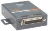
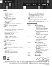
... Software utilities (DeviceInstaller and Com Port Redirector) - Six-foot DB9F-to chassis ground ORDERING INFORMATION + Part Number + Description UD1100001-01 UDS1100 one -port device server with regional adapters - Quick Start Guide UD110000B-01 UDS1100 one -port device server - 100-240 VAC International power supply with PoE - Quick Start Guide UD2100002-01 UDS2100 two-port device server - 100-240 VAC International power supply with shield connected to -DB25M serial cable (P/N 500-163-R) - and 4-wire configurations supported...
... Software utilities (DeviceInstaller and Com Port Redirector) - Six-foot DB9F-to chassis ground ORDERING INFORMATION + Part Number + Description UD1100001-01 UDS1100 one -port device server with regional adapters - Quick Start Guide UD110000B-01 UDS1100 one -port device server - 100-240 VAC International power supply with PoE - Quick Start Guide UD2100002-01 UDS2100 two-port device server - 100-240 VAC International power supply with shield connected to -DB25M serial cable (P/N 500-163-R) - and 4-wire configurations supported...

UDS1100 - Quick Start Guide
Page 7
... does not launch automatically: a) Click the Start button on the Task Bar and select Run. For standard UDS1100 units, supply power to the numbers in the packaging. 4. Respond to the RJ45 port. 3. WWW.LANTRONIX.COM 5 Insert the CD into your CD drive letter, colon, backslash, Launch.exe (e.g., E:\Launch.exe). 2. span or POE Ethernet switch. CONNECT Complete the following steps in order...
... does not launch automatically: a) Click the Start button on the Task Bar and select Run. For standard UDS1100 units, supply power to the numbers in the packaging. 4. Respond to the RJ45 port. 3. WWW.LANTRONIX.COM 5 Insert the CD into your CD drive letter, colon, backslash, Launch.exe (e.g., E:\Launch.exe). 2. span or POE Ethernet switch. CONNECT Complete the following steps in order...
UDS1100 - User Guide
Page 5
... Entering Monitor Mode Using the Serial Port 64 Entering Monitor Mode Using the Network Port 64 Monitor Mode Commands 64 A: Troubleshootingand Contact Information 67 LEDs 67 Problems and Error Messages 68 Technical Support 70 B: Connections and Pinouts 71 Serial Port 71 Serial Connector Pinouts 71 Modem Cable 72 Network Port 73 Ethernet Connector Pinouts 74 Power Plug 74 C: Technical Specifications 75 D: Mounting Brackets 77 E: Alternative Ways to Assign an IP Address 78 DHCP 78 AutoIP 78 UDS1100 User Guide 5
... Entering Monitor Mode Using the Serial Port 64 Entering Monitor Mode Using the Network Port 64 Monitor Mode Commands 64 A: Troubleshootingand Contact Information 67 LEDs 67 Problems and Error Messages 68 Technical Support 70 B: Connections and Pinouts 71 Serial Port 71 Serial Connector Pinouts 71 Modem Cable 72 Network Port 73 Ethernet Connector Pinouts 74 Power Plug 74 C: Technical Specifications 75 D: Mounting Brackets 77 E: Alternative Ways to Assign an IP Address 78 DHCP 78 AutoIP 78 UDS1100 User Guide 5

UDS1100 - User Guide
Page 7
... Connected to Serial Device and Network _________ 15 Figure 5-1. Channel Serial Settings 29 Figure 5-7. DB25 Female DCE Interface RS232 71 Figure B-3. BootP/DHCP/AutoIP options 38 Table 7-2. Firmware Files 61 Table 11-1. Interface Mode 42 Figure 8-3. Manual Connection Address Example 46 Table 8-7. Problems and Error Messages 68 Table C-1. Wiring Diagram for Lantronix Modem Cable, Part No. 500-163 ________ 73 List of Figures Figure 2-1. Server Settings 26 Figure 5-5. Flush Mode...
... Connected to Serial Device and Network _________ 15 Figure 5-1. Channel Serial Settings 29 Figure 5-7. DB25 Female DCE Interface RS232 71 Figure B-3. BootP/DHCP/AutoIP options 38 Table 7-2. Firmware Files 61 Table 11-1. Interface Mode 42 Figure 8-3. Manual Connection Address Example 46 Table 8-7. Problems and Error Messages 68 Table C-1. Wiring Diagram for Lantronix Modem Cable, Part No. 500-163 ________ 73 List of Figures Figure 2-1. Server Settings 26 Figure 5-5. Flush Mode...

UDS1100 - User Guide
Page 8
... Serial Port (Setup Mode interface) using DeviceInstaller or a serial port connection. 4: Configuration Using Web- 1: Using This Guide Purpose and Audience This guide provides the information needed to contact Lantronix Technical Support. E: Alternative Ways to Assign Provides detailed information about using the command line interface to monitor the network and diagnose problems. A: Troubleshooting and Contact Information Describes common problems and error messages and how to configure, use, and update the UDS1100 device server. C:Technical Specifications Lists technical...
... Serial Port (Setup Mode interface) using DeviceInstaller or a serial port connection. 4: Configuration Using Web- 1: Using This Guide Purpose and Audience This guide provides the information needed to contact Lantronix Technical Support. E: Alternative Ways to Assign Provides detailed information about using the command line interface to monitor the network and diagnose problems. A: Troubleshooting and Contact Information Describes common problems and error messages and how to configure, use, and update the UDS1100 device server. C:Technical Specifications Lists technical...

UDS1100 - User Guide
Page 12
... serial port. TFTP for firmware updates. IP for addressing, routing, and data block handling over the network. User Datagram Protocol (UDP) for typical datagram applications in web server for configuring the unit and displaying operating and troubleshooting information on a PC attached to a network. (See 4: Using DeviceInstaller.) Web-Manager: Through a web browser, configure the UDS settings using a Graphical User Interface (GUI) on the attached links to online support...
... serial port. TFTP for firmware updates. IP for addressing, routing, and data block handling over the network. User Datagram Protocol (UDP) for typical datagram applications in web server for configuring the unit and displaying operating and troubleshooting information on a PC attached to a network. (See 4: Using DeviceInstaller.) Web-Manager: Through a web browser, configure the UDS settings using a Graphical User Interface (GUI) on the attached links to online support...

UDS1100 - User Guide
Page 17
... must be downloaded from the list of DeviceInstaller from http://www.lantronix.com/support/downloads. 2. The hardware address is normally set to configure the IP address and related settings or for viewing its current configuration. If your PC has more advanced features, see the DeviceInstaller Online Help. On a local network, you may change it can leave the Default gateway blank (all zeros). UDS1100 User Guide 17
... must be downloaded from the list of DeviceInstaller from http://www.lantronix.com/support/downloads. 2. The hardware address is normally set to configure the IP address and related settings or for viewing its current configuration. If your PC has more advanced features, see the DeviceInstaller Online Help. On a local network, you may change it can leave the Default gateway blank (all zeros). UDS1100 User Guide 17

UDS1100 - User Guide
Page 18
.... To change the DHCP device name, see Configuration Using Web-Manager or Configuration via Telnet or Serial Port (Setup Mode). To perform this step, click the Search icon . Click StartPrograms LantronixDeviceInstallerDeviceInstaller. 2. Click the Assign button and wait several seconds until a confirmation message displays. Select the device from the main window list and select Ping from the Tools menu...
.... To change the DHCP device name, see Configuration Using Web-Manager or Configuration via Telnet or Serial Port (Setup Mode). To perform this step, click the Search icon . Click StartPrograms LantronixDeviceInstallerDeviceInstaller. 2. Click the Assign button and wait several seconds until a confirmation message displays. Select the device from the main window list and select Ping from the Tools menu...

UDS1100 - User Guide
Page 20
.... Details about the unit display. 2. UDS1100 User Guide 20 Displays False. Displays False. Displays True. Continue with 6: Configuration via Telnet or Serial Port (Setup Mode). Displays the UDS1100's maximum baud rate. Non-configurable field. 4: Using DeviceInstaller Web Port Maximum Baud Rate Supported Firmware Upgradeable Supports Configurable Pins Supports Email Triggers Supports AES Data Stream Supports 485 Supports 921K Baud Rate Supports HTTP Server Supports HTTP Setup Supports 230K Baud Rate Supports GPIO Non-configurable field. UDS1100 supports the RS-485...
.... Details about the unit display. 2. UDS1100 User Guide 20 Displays False. Displays False. Displays True. Continue with 6: Configuration via Telnet or Serial Port (Setup Mode). Displays the UDS1100's maximum baud rate. Non-configurable field. 4: Using DeviceInstaller Web Port Maximum Baud Rate Supported Firmware Upgradeable Supports Configurable Pins Supports Email Triggers Supports AES Data Stream Supports 485 Supports 921K Baud Rate Supports HTTP Server Supports HTTP Setup Supports 230K Baud Rate Supports GPIO Non-configurable field. UDS1100 supports the RS-485...

UDS1100 - User Guide
Page 29
... follows the data and parity bits in a transmitted data package. UDS1100 User Guide 29 Figure 5-6. Flow control manages data flow between devices in a network to display the Serial Settings window. Checks for the selected channel. Indicates the number of transmission. The default setting is enabled by default. On the main menu, click Serial Settings (under Channel 1) to ensure it causes lost or retransmitted data. The serial port is 8. Port Settings Protocol Flow Control Baud Rate Data Bits Parity...
... follows the data and parity bits in a transmitted data package. UDS1100 User Guide 29 Figure 5-6. Flow control manages data flow between devices in a network to display the Serial Settings window. Checks for the selected channel. Indicates the number of transmission. The default setting is enabled by default. On the main menu, click Serial Settings (under Channel 1) to ensure it causes lost or retransmitted data. The serial port is 8. Port Settings Protocol Flow Control Baud Rate Data Bits Parity...

UDS1100 - User Guide
Page 35
... to set factory settings, or click No to identify units on the device. the Apply Settings button makes the changes permanent and reboots the UDS1100. Apply Defaults 1. Note: Lantronix Tech Support supports Datagram type 01. Figure 5-9. Note: Clicking OK on each page does not change the configuration on the local network of device servers. Apply Settings and Apply Defaults UDS1100 User Guide 35 On the main menu, click Apply Settings. Clicking...
... to set factory settings, or click No to identify units on the device. the Apply Settings button makes the changes permanent and reboots the UDS1100. Apply Defaults 1. Note: Lantronix Tech Support supports Datagram type 01. Figure 5-9. Note: Clicking OK on each page does not change the configuration on the local network of device servers. Apply Settings and Apply Defaults UDS1100 User Guide 35 On the main menu, click Apply Settings. Clicking...

UDS1100 - User Guide
Page 37
... to hold down the x key at the terminal (or emulation) while resetting the unit. All values are stored in Telnet Connection, above. UDS1100 User Guide 37 Setup Menu Options Change Setup: 0 Server 1 Channel 1 5 Expert 6 Security 7 Defaults 8 Exit without saving any changes or rebooting. Serial Port Connection To configure the unit through which to your unit's serial port. You must do this point, the screen display is to enter Setup Mode is the same as when...
... to hold down the x key at the terminal (or emulation) while resetting the unit. All values are stored in Telnet Connection, above. UDS1100 User Guide 37 Setup Menu Options Change Setup: 0 Server 1 Channel 1 5 Expert 6 Security 7 Defaults 8 Exit without saving any changes or rebooting. Serial Port Connection To configure the unit through which to your unit's serial port. You must do this point, the screen display is to enter Setup Mode is the same as when...

UDS1100 - User Guide
Page 43
... not use this setting as incorrect operation may result. The port range is C0. UDS1100 User Guide 43 ConnectMode (C0) ? _ Enter Connect Mode options in a passive mode or when using TCP. The range is 1-65535, except for Port 1 is in hexadecimal notation. Use Port 0 for remote initiating connections. Connect Mode Connect Mode defines how the unit makes a connection, and how it wraps back around to host 05 Port Number The setting represents the source port number in TCP connections. The default setting...
... not use this setting as incorrect operation may result. The port range is C0. UDS1100 User Guide 43 ConnectMode (C0) ? _ Enter Connect Mode options in a passive mode or when using TCP. The range is 1-65535, except for Port 1 is in hexadecimal notation. Use Port 0 for remote initiating connections. Connect Mode Connect Mode defines how the unit makes a connection, and how it wraps back around to host 05 Port Number The setting represents the source port number in TCP connections. The default setting...

UDS1100 - User Guide
Page 45
... List is required between each pair of the remote IP address. 8: Setup Mode: Channel Configuration b) Response Character Response c) Active Startup No Active Startup With Any Character With active Modem Control in With a Specific Start Character Manual Connection A single character is transmitted to the serial port when there is Nothing (quiet). Default setting is a change in the command string. The slash separates the IP address and the port number...
... List is required between each pair of the remote IP address. 8: Setup Mode: Channel Configuration b) Response Character Response c) Active Startup No Active Startup With Any Character With active Modem Control in With a Specific Start Character Manual Connection A single character is transmitted to the serial port when there is Nothing (quiet). Default setting is a change in the command string. The slash separates the IP address and the port number...

UDS1100 - User Guide
Page 47
... a local PC and a modem connected to use an Ethernet connection instead of seconds the unit should try to make a good network connection to the echo of the characters entered in the UDS1100 User Guide 47 The time is 1-15, with UDS1100s, and to a remote machine. After completing the hostlist, repeat the previous step if necessary to the commands received (or displaying what was typed).
... a local PC and a modem connected to use an Ethernet connection instead of seconds the unit should try to make a good network connection to the echo of the characters entered in the UDS1100 User Guide 47 The time is 1-15, with UDS1100s, and to a remote machine. After completing the hostlist, repeat the previous step if necessary to the commands received (or displaying what was typed).
UDS1100 - User Guide
Page 54
With this option enabled, you can set a password on the serial port. The default setting is enabled in Disconnect Mode. Channel (Port) Password This parameter appears only if the channel (port) password option is all 0s. 8: Setup Mode: Channel Configuration With terminal type option enabled, the unit also reacts to the EOR (end of record) and binary options, useful for applications like terminal emulation to IBM hosts. UDS1100 User Guide 54
With this option enabled, you can set a password on the serial port. The default setting is enabled in Disconnect Mode. Channel (Port) Password This parameter appears only if the channel (port) password option is all 0s. 8: Setup Mode: Channel Configuration With terminal type option enabled, the unit also reacts to the EOR (end of record) and binary options, useful for applications like terminal emulation to IBM hosts. UDS1100 User Guide 54

UDS1100 - User Guide
Page 67
... Blinks 2x/second ON Setup menu active UDS1100 User Guide 67 Confirm that you are secure. If the Diagnostic LED is powered up. When troubleshooting the following table explains the LED functions: Diagnostic LED Table A-1. A: Troubleshooting and Contact Information This chapter discusses how you can diagnose and fix errors quickly without having to view summary messages that may display. It helps to connect a terminal to the serial port...
... Blinks 2x/second ON Setup menu active UDS1100 User Guide 67 Confirm that you are secure. If the Diagnostic LED is powered up. When troubleshooting the following table explains the LED functions: Diagnostic LED Table A-1. A: Troubleshooting and Contact Information This chapter discusses how you can diagnose and fix errors quickly without having to view summary messages that may display. It helps to connect a terminal to the serial port...
UDS1100 - User Guide
Page 69
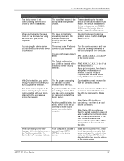
... Status LED is blinking consistently, then there is solid green, then the socket connection does not exist. Use Connect Mode option C1 or C5 for the UDS. UDS1100 User Guide 69 Solution The serial settings for making a connection to or from the network. There may not be set up correctly, but not Telnet to verify that you get the Wrong Password error when you are...
... Status LED is blinking consistently, then there is solid green, then the socket connection does not exist. Use Connect Mode option C1 or C5 for the UDS. UDS1100 User Guide 69 Solution The serial settings for making a connection to or from the network. There may not be set up correctly, but not Telnet to verify that you get the Wrong Password error when you are...
UDS1100 - User Guide
Page 84
... Searching for on the Network, 18 Show After RING, 50 Label, 13 LEDs, 67 MAC Address, 13 Manufacturer's Name & Address, 82 Modem Emulation, 12 Modem Mode, 47 Monitor Mode, 64 Mounting Brackets, 77 Netmask, 39 Network Settings, 24 Null Modem Cable, 72 Pack Control, 52 Package Contents, 14 Password for Telnet Configuration, 39 Pinouts, 71 Ethernet Connector, 74 Serial Connector, 71 Port Number, 43 Port Password, 54 Power plug, 73 Problems...
... Searching for on the Network, 18 Show After RING, 50 Label, 13 LEDs, 67 MAC Address, 13 Manufacturer's Name & Address, 82 Modem Emulation, 12 Modem Mode, 47 Monitor Mode, 64 Mounting Brackets, 77 Netmask, 39 Network Settings, 24 Null Modem Cable, 72 Pack Control, 52 Package Contents, 14 Password for Telnet Configuration, 39 Pinouts, 71 Ethernet Connector, 74 Serial Connector, 71 Port Number, 43 Port Password, 54 Power plug, 73 Problems...

UDS1100 - User Guide
Page 85
...-485/422 Standards, 71 Security Settings, 57 Send Characters, 53 Serial Port Accessing Setup Mode, 21 Login, 21 Serial Settings Setup Mode, 41 Serial Tunneling, 10 Server Settings Setup Mode, 38 Web-Manager, 26 Setup Mode, 36 Serial Port Connection, 37 Telnet Connection, 36 SNMP, 57 TCP Settings, 31 Technical Specifications Technical Support, 70 Telnet Terminal Type, 54 TFTP, 61 Trademark, 2 Troubleshooting, 8, 67 UDP Settings, 34 Using DeviceInstaller, 17 Warranty, 2 Web-Manager, 22 Index UDS1100 User Guide 85
...-485/422 Standards, 71 Security Settings, 57 Send Characters, 53 Serial Port Accessing Setup Mode, 21 Login, 21 Serial Settings Setup Mode, 41 Serial Tunneling, 10 Server Settings Setup Mode, 38 Web-Manager, 26 Setup Mode, 36 Serial Port Connection, 37 Telnet Connection, 36 SNMP, 57 TCP Settings, 31 Technical Specifications Technical Support, 70 Telnet Terminal Type, 54 TFTP, 61 Trademark, 2 Troubleshooting, 8, 67 UDP Settings, 34 Using DeviceInstaller, 17 Warranty, 2 Web-Manager, 22 Index UDS1100 User Guide 85


