
UDS1100/UDS2100 - Product Brief
Page 1
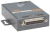
...to, monitor, and control their equipment from network-enabled equipment DeviceLinx™ Think it. Connect it . Control it . Supplied with Lantronix' TruPort® COM Port Redirector software, UDS creates a fully transparent serial connection to existing PC-based software applications-making it possible...equipment already in one and two-port models, and equipped with flexible power options including PoE, the UDS makes it were connected to a local PC serial port. UDS1100/2100 Family Serial Device Servers RELIABLE DEVICE SERVERS FOR AFFORDABLE SERIAL-TO-ETHERNET CONNECTIVITY The ...
...to, monitor, and control their equipment from network-enabled equipment DeviceLinx™ Think it. Connect it . Control it . Supplied with Lantronix' TruPort® COM Port Redirector software, UDS creates a fully transparent serial connection to existing PC-based software applications-making it possible...equipment already in one and two-port models, and equipped with flexible power options including PoE, the UDS makes it were connected to a local PC serial port. UDS1100/2100 Family Serial Device Servers RELIABLE DEVICE SERVERS FOR AFFORDABLE SERIAL-TO-ETHERNET CONNECTIVITY The ...
UDS1100/UDS2100 - Product Brief
Page 2
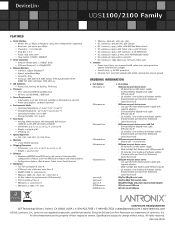
...; Power, Link, Activity, RX Activity, TX Activity + Processor • CPU: Lantronix DSTNI-EX 48 MHz clock • Memory: 256 KB SRAM, 2 MB Flash + Power Requirements • Input supply: 9-30 VDC (PoE only available on UD11000P0-01 version) • Power Consumption: 1.8 Watts maximum + ... over voltages • Serial Port(s): 15 KV ESD protection • Ethernet Port: 1500 VAC isolation with PoE - Quick Start Guide UD110000B-01 UDS1100 one -port device server - 100-240 VAC International power supply with regional adapters - CD Includes: User Guide...
...; Power, Link, Activity, RX Activity, TX Activity + Processor • CPU: Lantronix DSTNI-EX 48 MHz clock • Memory: 256 KB SRAM, 2 MB Flash + Power Requirements • Input supply: 9-30 VDC (PoE only available on UD11000P0-01 version) • Power Consumption: 1.8 Watts maximum + ... over voltages • Serial Port(s): 15 KV ESD protection • Ethernet Port: 1500 VAC isolation with PoE - Quick Start Guide UD110000B-01 UDS1100 one -port device server - 100-240 VAC International power supply with regional adapters - CD Includes: User Guide...

UDS1100 - Quick Start Guide
Page 4
Quick Start Guide UDS1100 WHAT'S IN THE BOX In addition to the UDS, the box contains the following items: POWER SUPPLY (DOMESTIC UNITS) PART # COMPONENT DESCRIPTION 520-079-R Power cube, 110 VAC 500-163 Serial Cable CD Power Cord Restraint POWER SUPPLY (INTERNATIONAL UNITS) PART # COMPONENT DESCRIPTION 520-080-R* Power cube, 100-240VAC, with international adapters 500-163 Serial Cable CD Power Cord Restraint * Not included with UDS1100 POE version DOCUMENTATION: CD-ROM containing User Guide and software utilities and Quick Start Guide. 2
Quick Start Guide UDS1100 WHAT'S IN THE BOX In addition to the UDS, the box contains the following items: POWER SUPPLY (DOMESTIC UNITS) PART # COMPONENT DESCRIPTION 520-079-R Power cube, 110 VAC 500-163 Serial Cable CD Power Cord Restraint POWER SUPPLY (INTERNATIONAL UNITS) PART # COMPONENT DESCRIPTION 520-080-R* Power cube, 100-240VAC, with international adapters 500-163 Serial Cable CD Power Cord Restraint * Not included with UDS1100 POE version DOCUMENTATION: CD-ROM containing User Guide and software utilities and Quick Start Guide. 2

UDS1100 - Quick Start Guide
Page 5
This Quick Start explains how to the User Guide on the CD. For more detailed information or alternative configuration methods, refer to connect, configure, and troubleshoot your unit using a network connection and our DeviceInstaller software. PINOUTS * *Not included in UDS1100 POE version WWW.LANTRONIX.COM 3 The UDS products allow serial devices to connect and communicate over an Ethernet network.
This Quick Start explains how to the User Guide on the CD. For more detailed information or alternative configuration methods, refer to connect, configure, and troubleshoot your unit using a network connection and our DeviceInstaller software. PINOUTS * *Not included in UDS1100 POE version WWW.LANTRONIX.COM 3 The UDS products allow serial devices to connect and communicate over an Ethernet network.

UDS1100 - Quick Start Guide
Page 7
...Start button on the Task Bar and select Run. Refer to your unit. 2. For the UDS1100-POE version, power is 9-30 VDC (center +) or 9-24 VAC (1.5W maximum power required). WWW.LANTRONIX.COM 5 CONNECT Complete the following steps in the figure below. 1. Connect a serial device to... the RJ45 port. 3. Click the DeviceInstaller button. 3. span or POE Ethernet switch. b) Enter your CD-ROM drive. Ethernet, Power, ...
...Start button on the Task Bar and select Run. Refer to your unit. 2. For the UDS1100-POE version, power is 9-30 VDC (center +) or 9-24 VAC (1.5W maximum power required). WWW.LANTRONIX.COM 5 CONNECT Complete the following steps in the figure below. 1. Connect a serial device to... the RJ45 port. 3. Click the DeviceInstaller button. 3. span or POE Ethernet switch. b) Enter your CD-ROM drive. Ethernet, Power, ...

UDS1100 - User Guide
Page 2
... Firefox® are registered trademarks of Microsoft Corporation. Warranty For details on the Lantronix warranty policy, please go to add UDS1100-POE version. The manufacturer assumes no responsibility for any means without notice. Changes to our Web site at www.lantronix.com/about/contact. Windows® and Internet Explorer® are registered trademarks of...
... Firefox® are registered trademarks of Microsoft Corporation. Warranty For details on the Lantronix warranty policy, please go to add UDS1100-POE version. The manufacturer assumes no responsibility for any means without notice. Changes to our Web site at www.lantronix.com/about/contact. Windows® and Internet Explorer® are registered trademarks of...

UDS1100 - User Guide
Page 7
... Example 46 Table 8-7. Flush Mode Options 52 Table 8-11. Serial Tunneling Example 11 Figure 2-2. UDS1100-POE Version Connected to Serial Device and Network _________ 15 Figure 5-1. Disconnect Mode Options 51 Table 8-10. Command Response Codes 66 Table A-1. Lantronix Web-Manager 23 Figure 5-3. TFTP Window 62 Figure B-1. Firmware Files 61 Table 11-1. Monitor Mode...
... Example 46 Table 8-7. Flush Mode Options 52 Table 8-11. Serial Tunneling Example 11 Figure 2-2. UDS1100-POE Version Connected to Serial Device and Network _________ 15 Figure 5-1. Disconnect Mode Options 51 Table 8-10. Command Response Codes 66 Table A-1. Lantronix Web-Manager 23 Figure 5-3. TFTP Window 62 Figure B-1. Firmware Files 61 Table 11-1. Monitor Mode...

UDS1100 - User Guide
Page 14
... list. Package Contents Verify and inspect the contents of UDS1100 This chapter describes how to install your place of purchase immediately. UDS1100 Six-foot DB9F-to Serial Device and Network UDS1100 User Guide 14 UDS1100-POE Version Connected to -DB25M modem cable (P/N 500-163 ...) Power supply (non Power Over Ethernet (POE) units only) Quick Start Guide ...
... list. Package Contents Verify and inspect the contents of UDS1100 This chapter describes how to install your place of purchase immediately. UDS1100 Six-foot DB9F-to Serial Device and Network UDS1100 User Guide 14 UDS1100-POE Version Connected to -DB25M modem cable (P/N 500-163 ...) Power supply (non Power Over Ethernet (POE) units only) Quick Start Guide ...

UDS1100 - User Guide
Page 15
Connect a serial device to your unit using an 802.3af POE-compliant power source such as a POE mid-span or POE Ethernet switch. 4. For non-POE UDS1100 unit, supply power to your unit over the Ethernet interface using the power supply that follow for details about connectors and pinouts. ...1. Supply power to the RJ45 port. 3. Note: If you encounter a problem, please see LEDs for the non-POE UDS1100 is supplied to your unit. 2. Note: See the sections that was included in the packaging. Note: The required input voltage for diagnostic information...
Connect a serial device to your unit using an 802.3af POE-compliant power source such as a POE mid-span or POE Ethernet switch. 4. For non-POE UDS1100 unit, supply power to your unit over the Ethernet interface using the power supply that follow for details about connectors and pinouts. ...1. Supply power to the RJ45 port. 3. Note: If you encounter a problem, please see LEDs for the non-POE UDS1100 is supplied to your unit. 2. Note: See the sections that was included in the packaging. Note: The required input voltage for diagnostic information...

UDS1100 - User Guide
Page 71
B: Connections and Pinouts Serial Port The UDS has a female DCE DB25 serial port that supports RS-232 and RS-485/422 serial standards (software selectable) up to 230 Kbaud. UDS1100 User Guide 71 Figure B-2. DB25 Female DCE Interface RS232 *Optional power connection for non-POE unit. Serial Interface DB25 Serial Port Serial Connector Pinouts The unit's female DB25 connector provides an RS-232C, RS-485, or RS-422 DCE serial port. The default serial port settings are 9600 baud, 8 bits, no parity, and 1 stop bit. Figure B-1.
B: Connections and Pinouts Serial Port The UDS has a female DCE DB25 serial port that supports RS-232 and RS-485/422 serial standards (software selectable) up to 230 Kbaud. UDS1100 User Guide 71 Figure B-2. DB25 Female DCE Interface RS232 *Optional power connection for non-POE unit. Serial Interface DB25 Serial Port Serial Connector Pinouts The unit's female DB25 connector provides an RS-232C, RS-485, or RS-422 DCE serial port. The default serial port settings are 9600 baud, 8 bits, no parity, and 1 stop bit. Figure B-1.

UDS1100 - User Guide
Page 72
UDS1100 User Guide 72 The figure below shows the pinouts for non-POE unit. Figure B-4. DB25 Female Interface RS422 (4 wire mode) *Optional power connection for a DB25 to as a "Modem Cable". To configure the UDS using the DB9 serial port, you need only pin out the TXD, RXD, and GND signals. B: Connections and Pinouts Figure B-3. DB25 Female Interface RS485 (2 wire mode) Modem Cable When attaching the DB25 of the UDS to the DB9 com port on a PC, use a standard straight-through cable, often referred to DB9 straight-through serial cable (Lantronix Part No. 500-163).
UDS1100 User Guide 72 The figure below shows the pinouts for non-POE unit. Figure B-4. DB25 Female Interface RS422 (4 wire mode) *Optional power connection for a DB25 to as a "Modem Cable". To configure the UDS using the DB9 serial port, you need only pin out the TXD, RXD, and GND signals. B: Connections and Pinouts Figure B-3. DB25 Female Interface RS485 (2 wire mode) Modem Cable When attaching the DB25 of the UDS to the DB9 com port on a PC, use a standard straight-through cable, often referred to DB9 straight-through serial cable (Lantronix Part No. 500-163).

UDS1100 - User Guide
Page 73
Figure B-6. Wiring Diagram for Lantronix Modem Cable, Part No. 500-163 Network Port The standard UDS1100 non-POE version unit's back panel contains a power plug and an RJ45 (10/100) Ethernet port. The UDS1100-POE version does not have a power plug; it is powered through the Ethernet interface using 802.3af Power over Ethernet. Network Interface RJ45 Ethernet Port Power Plug UDS1100 User Guide 73 B: Connections and Pinouts Figure B-5.
Figure B-6. Wiring Diagram for Lantronix Modem Cable, Part No. 500-163 Network Port The standard UDS1100 non-POE version unit's back panel contains a power plug and an RJ45 (10/100) Ethernet port. The UDS1100-POE version does not have a power plug; it is powered through the Ethernet interface using 802.3af Power over Ethernet. Network Interface RJ45 Ethernet Port Power Plug UDS1100 User Guide 73 B: Connections and Pinouts Figure B-5.

UDS1100 - User Guide
Page 75
... Flash EEPROM Serial Interface Serial Line Formats Modem Control Flow Control Power Input Network Interface Dimensions Weight Temperature Table C-1. UDS1100 Technical Specifications Description Lantronix DSTNI-EX 48 MHz clock 256 KB zero wait state SRAM 2 MB Flash 2 KB EEPROM 1 DB25F DCE ...) 9-30 VDC or 9-24 VAC on barrel connector (1.5 Watts maximum consumption) 9-30 VDC on DB25F serial interface UDS1100-POE only 802.3af Power over Ethernet (UDS1100-POE only) 1 RJ45 10Base-T/100Base-TX Ethernet port Software selectable Ethernet speed 10/100/Auto Software selectable Half/Full/Auto duplex ...
... Flash EEPROM Serial Interface Serial Line Formats Modem Control Flow Control Power Input Network Interface Dimensions Weight Temperature Table C-1. UDS1100 Technical Specifications Description Lantronix DSTNI-EX 48 MHz clock 256 KB zero wait state SRAM 2 MB Flash 2 KB EEPROM 1 DB25F DCE ...) 9-30 VDC or 9-24 VAC on barrel connector (1.5 Watts maximum consumption) 9-30 VDC on DB25F serial interface UDS1100-POE only 802.3af Power over Ethernet (UDS1100-POE only) 1 RJ45 10Base-T/100Base-TX Ethernet port Software selectable Ethernet speed 10/100/Auto Software selectable Half/Full/Auto duplex ...