UDS1100/UDS2100 - Product Brief
Page 2
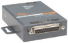
... and power input terminal adapter ACDIN1001-01 DIN-rail mount UDS1100 ACDIN2001-01 DIN-rail mount UDS2100 CORPORATE HEADQUARTERS 167 Technology Drive | Irvine | CA 92618 | USA | t: 800.422.7055 | f: 949.450.7232 | sales@lantronix.com | www.lantronix.com ©2009, Lantronix, Inc. CD Includes: User Guide and Software utilities (DeviceInstaller and Com Port Redirector) - and 4-wire...
... and power input terminal adapter ACDIN1001-01 DIN-rail mount UDS1100 ACDIN2001-01 DIN-rail mount UDS2100 CORPORATE HEADQUARTERS 167 Technology Drive | Irvine | CA 92618 | USA | t: 800.422.7055 | f: 949.450.7232 | sales@lantronix.com | www.lantronix.com ©2009, Lantronix, Inc. CD Includes: User Guide and Software utilities (DeviceInstaller and Com Port Redirector) - and 4-wire...

UDS1100 - Quick Start Guide
Page 4
Quick Start Guide UDS1100 WHAT'S IN THE BOX In addition to the UDS, the box contains the following items: POWER SUPPLY (DOMESTIC UNITS) PART # COMPONENT DESCRIPTION 520-079-R Power cube, 110 VAC 500-163 Serial Cable CD Power Cord Restraint POWER SUPPLY (INTERNATIONAL UNITS) PART # COMPONENT DESCRIPTION 520-080-R* Power cube, 100-240VAC, with international adapters 500-163 Serial Cable CD Power Cord Restraint * Not included with UDS1100 POE version DOCUMENTATION: CD-ROM containing User Guide and software utilities and Quick Start Guide. 2
Quick Start Guide UDS1100 WHAT'S IN THE BOX In addition to the UDS, the box contains the following items: POWER SUPPLY (DOMESTIC UNITS) PART # COMPONENT DESCRIPTION 520-079-R Power cube, 110 VAC 500-163 Serial Cable CD Power Cord Restraint POWER SUPPLY (INTERNATIONAL UNITS) PART # COMPONENT DESCRIPTION 520-080-R* Power cube, 100-240VAC, with international adapters 500-163 Serial Cable CD Power Cord Restraint * Not included with UDS1100 POE version DOCUMENTATION: CD-ROM containing User Guide and software utilities and Quick Start Guide. 2

UDS1100 - Quick Start Guide
Page 5
This Quick Start explains how to the User Guide on the CD. For more detailed information or alternative configuration methods, refer to connect, configure, and troubleshoot your unit using a network connection and our DeviceInstaller software. PINOUTS * *Not included in UDS1100 POE version WWW.LANTRONIX.COM 3 The UDS products allow serial devices to connect and communicate over an Ethernet network.
This Quick Start explains how to the User Guide on the CD. For more detailed information or alternative configuration methods, refer to connect, configure, and troubleshoot your unit using a network connection and our DeviceInstaller software. PINOUTS * *Not included in UDS1100 POE version WWW.LANTRONIX.COM 3 The UDS products allow serial devices to connect and communicate over an Ethernet network.
UDS1100 - Quick Start Guide
Page 12
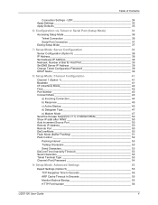
DeviceInstaller locates the unit and adds it . Double-click the unit in the device list, it can manage and configure it to the list of the following tabs: Note: For details about the unit display. 2. Select one of similar Lantronix devices on the network so that you can be configured. 1. Details about configuration settings, see the UDS User Guide. 10 To perform this step, click the Search icon . CONFIGURATION Once the UDS is in the list. Quick Start Guide UDS1100 ADDING THE UNIT TO THE DEVICE LIST Now add the unit to the list.
DeviceInstaller locates the unit and adds it . Double-click the unit in the device list, it can manage and configure it to the list of the following tabs: Note: For details about the unit display. 2. Select one of similar Lantronix devices on the network so that you can be configured. 1. Details about configuration settings, see the UDS User Guide. 10 To perform this step, click the Search icon . CONFIGURATION Once the UDS is in the list. Quick Start Guide UDS1100 ADDING THE UNIT TO THE DEVICE LIST Now add the unit to the list.

UDS1100 - User Guide
Page 2
... Rev. Updated for firmware v6.8. Updated to operating and storage temperatures. UDS1100 User Guide 2 Lantronix® is a registered trademark and UDS™ and DeviceInstaller™ are registered trademarks of Lantronix. No part of the contents of their respective holders. Mozilla® and...transmitted or reproduced in this guide may appear in this guide. Changes to add UDS1100-POE version. Warranty For details on the Lantronix warranty policy, please go to our Web site at www.lantronix.com/about/contact. Contacts Lantronix Corporate Headquarters 167 Technology ...
... Rev. Updated for firmware v6.8. Updated to operating and storage temperatures. UDS1100 User Guide 2 Lantronix® is a registered trademark and UDS™ and DeviceInstaller™ are registered trademarks of Lantronix. No part of the contents of their respective holders. Mozilla® and...transmitted or reproduced in this guide may appear in this guide. Changes to add UDS1100-POE version. Warranty For details on the Lantronix warranty policy, please go to our Web site at www.lantronix.com/about/contact. Contacts Lantronix Corporate Headquarters 167 Technology ...

UDS1100 - User Guide
Page 3
... Address: Serial Port Login 21 5: Configuration Using Web-Manager 22 Accessing UDS1100 Using DeviceInstaller 22 Network Configuration 24 Network Mode 24 Automatic IP Address Configuration 24 Static IP Address Configuration 25 Ethernet Configuration 26 Server Configuration 26 Host List Configuration 27 Channel 1 Configuration 28 Serial Settings 28 Connection Settings - TCP 31 UDS1100 User Guide 3
... Address: Serial Port Login 21 5: Configuration Using Web-Manager 22 Accessing UDS1100 Using DeviceInstaller 22 Network Configuration 24 Network Mode 24 Automatic IP Address Configuration 24 Static IP Address Configuration 25 Ethernet Configuration 26 Server Configuration 26 Host List Configuration 27 Channel 1 Configuration 28 Serial Settings 28 Connection Settings - TCP 31 UDS1100 User Guide 3
UDS1100 - User Guide
Page 4
... Expert Settings (Option 5 55 TCP Keepalive Time In Seconds 55 ARP Cache Timeout In Seconds 55 Monitor Mode at Bootup 55 HTTP Port Number 56 UDS1100 User Guide 4
... Expert Settings (Option 5 55 TCP Keepalive Time In Seconds 55 ARP Cache Timeout In Seconds 55 Monitor Mode at Bootup 55 HTTP Port Number 56 UDS1100 User Guide 4
UDS1100 - User Guide
Page 5
... Channel 1 Configuration Defaults 59 Expert Settings Defaults 59 Security Settings Defaults 60 10: Firmware Upgrades 61 Obtaining Firmware 61 Reloading Firmware 61 Using TFTP: Graphical User Interface 61 Using TFTP: Command Line Interface 62 Recovering the Firmware Using the Serial Port and DeviceInstaller _________ 62 11: Monitor Mode 64 Entering Monitor... Ethernet Connector Pinouts 74 Power Plug 74 C: Technical Specifications 75 D: Mounting Brackets 77 E: Alternative Ways to Assign an IP Address 78 DHCP 78 AutoIP 78 UDS1100 User Guide 5
... Channel 1 Configuration Defaults 59 Expert Settings Defaults 59 Security Settings Defaults 60 10: Firmware Upgrades 61 Obtaining Firmware 61 Reloading Firmware 61 Using TFTP: Graphical User Interface 61 Using TFTP: Command Line Interface 62 Recovering the Firmware Using the Serial Port and DeviceInstaller _________ 62 11: Monitor Mode 64 Entering Monitor... Ethernet Connector Pinouts 74 Power Plug 74 C: Technical Specifications 75 D: Mounting Brackets 77 E: Alternative Ways to Assign an IP Address 78 DHCP 78 AutoIP 78 UDS1100 User Guide 5

UDS1100 - User Guide
Page 6
Table of Contents BOOTP 79 ARP and Telnet 79 F: Binary to Hexadecimal Conversions 80 Converting Binary to Hexadecimal 80 Conversion Table 80 Scientific Calculator 81 G: Compliance 82 Index 84 UDS1100 User Guide 6
Table of Contents BOOTP 79 ARP and Telnet 79 F: Binary to Hexadecimal Conversions 80 Converting Binary to Hexadecimal 80 Conversion Table 80 Scientific Calculator 81 G: Compliance 82 Index 84 UDS1100 User Guide 6

UDS1100 - User Guide
Page 7
...Figure 5-1. Lantronix Web-Manager 23 Figure 5-3. Hostlist Settings 28 Figure 5-6. MAC Address 37 Figure 6-2. Interface Mode 42 Figure 8-3. Serial Interface 71 Figure B-2. Flush Mode Options 52 Table 8-11. Command Response Codes 66 Table A-1. UDS1100 Technical Specifications 75 UDS1100 User Guide 7 ... 46 Figure 9-1. Flow Control Options 43 Table 8-4. Problems and Error Messages 68 Table C-1. UDS1100 LEDs 67 Table A-2. List of Tables Table 7-1. Wiring Diagram for Lantronix Modem Cable, Part No. 500-163 ________ 73 List of Figures Figure 2-1. Modem Mode...
...Figure 5-1. Lantronix Web-Manager 23 Figure 5-3. Hostlist Settings 28 Figure 5-6. MAC Address 37 Figure 6-2. Interface Mode 42 Figure 8-3. Serial Interface 71 Figure B-2. Flush Mode Options 52 Table 8-11. Command Response Codes 66 Table A-1. UDS1100 Technical Specifications 75 UDS1100 User Guide 7 ... 46 Figure 9-1. Flow Control Options 43 Table 8-4. Problems and Error Messages 68 Table C-1. UDS1100 LEDs 67 Table A-2. List of Tables Table 7-1. Wiring Diagram for Lantronix Modem Cable, Part No. 500-163 ________ 73 List of Figures Figure 2-1. Modem Mode...

UDS1100 - User Guide
Page 8
...Details expert and security settings and explains how to reset the unit to contact Lantronix Technical Support. Chapter Summary The remaining chapters in this guide include: Chapter Description 2: Introduction Describes the main features of the UDS and the...Provides instructions for installing your unit and getting it supports. 3: Installation of UDS1100 Provides information for accessing and using DeviceInstaller or a serial port connection. 4: Configuration Using Web- UDS1100 User Guide 8 E: Alternative Ways to Assign Provides detailed information about using DHCP, ...
...Details expert and security settings and explains how to reset the unit to contact Lantronix Technical Support. Chapter Summary The remaining chapters in this guide include: Chapter Description 2: Introduction Describes the main features of the UDS and the...Provides instructions for installing your unit and getting it supports. 3: Installation of UDS1100 Provides information for accessing and using DeviceInstaller or a serial port connection. 4: Configuration Using Web- UDS1100 User Guide 8 E: Alternative Ways to Assign Provides detailed information about using DHCP, ...

UDS1100 - User Guide
Page 9
... the following additional documentation. Explain and demonstrate assigning an IP address to hexadecimals. UDS1100 User Guide 9 Provides Lantronix compliance information. Additional Documentation Visit the Lantronix Web site at www.lantronix.com/support/documentation for getting the UDS1100 up the UDS and Com Port Redirector. Document UDS1100 Quick Start DeviceInstaller Online Help "Live" Tutorials on using the Windows-based...
... the following additional documentation. Explain and demonstrate assigning an IP address to hexadecimals. UDS1100 User Guide 9 Provides Lantronix compliance information. Additional Documentation Visit the Lantronix Web site at www.lantronix.com/support/documentation for getting the UDS1100 up the UDS and Com Port Redirector. Document UDS1100 Quick Start DeviceInstaller Online Help "Live" Tutorials on using the Windows-based...

UDS1100 - User Guide
Page 10
Using two UDS units, connected by a network, virtual serial connections can extend across a facility or around the world. UDS1100 User Guide 10 2: Introduction The UDS1100 is a single-port device server that provides a quick, simple, and costeffective way to bring the advantages of Device Servers allows serial devices, such as those ...
Using two UDS units, connected by a network, virtual serial connections can extend across a facility or around the world. UDS1100 User Guide 10 2: Introduction The UDS1100 is a single-port device server that provides a quick, simple, and costeffective way to bring the advantages of Device Servers allows serial devices, such as those ...
UDS1100 - User Guide
Page 11
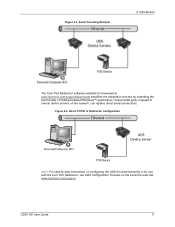
Serial Tunneling Example 2: Introduction The Com Port Redirector software available for download at www.lantronix.com/support/downloads simplifies the integration process by -step instructions on configuring the UDS for serial tunneling or for ...the network, can replace direct serial connections. Virtual COM ports, mapped to remote device servers on the Lantronix web site: www.lantronix.com/support. Direct TCP/IP or Redirector Configuration Note: For step-by extending the functionality of COM-port-based Windows™ applications. UDS1100 User Guide 11 Figure 2-2. Figure 2-1.
Serial Tunneling Example 2: Introduction The Com Port Redirector software available for download at www.lantronix.com/support/downloads simplifies the integration process by -step instructions on configuring the UDS for serial tunneling or for ...the network, can replace direct serial connections. Virtual COM ports, mapped to remote device servers on the Lantronix web site: www.lantronix.com/support. Direct TCP/IP or Redirector Configuration Note: For step-by extending the functionality of COM-port-based Windows™ applications. UDS1100 User Guide 11 Figure 2-2. Figure 2-1.

UDS1100 - User Guide
Page 12
... connections and bandwidth to operate correctly on a network, it must have a unique IP address on a PC attached to online support. UDS1100 User Guide 12 For the unit to eliminate dedicated modems and phone lines. See 6: Configuration via Telnet or Serial Port (Setup Mode). Additional Features...Emulation: In modem emulation mode, the UDS can replace dial-up modems. The unit accepts modem AT commands on the UDS using the Lantronix Web-Manager. (See 5: Configuration Using Web-Manager.) Serial and Telnet Ports: Use Setup Mode, a command line interface. Configuration Methods...
... connections and bandwidth to operate correctly on a network, it must have a unique IP address on a PC attached to online support. UDS1100 User Guide 12 For the unit to eliminate dedicated modems and phone lines. See 6: Configuration via Telnet or Serial Port (Setup Mode). Additional Features...Emulation: In modem emulation mode, the UDS can replace dial-up modems. The unit accepts modem AT commands on the UDS using the Lantronix Web-Manager. (See 5: Configuration Using Web-Manager.) Serial and Telnet Ports: Use Setup Mode, a command line interface. Configuration Methods...

UDS1100 - User Guide
Page 13
... fourth, fifth, and sixth bytes are fixed and read 00-20-4A, identifying the unit as a Lantronix product. Sample Hardware Address 00-20-4A-14-01-18 or 00:20:4A:14:01:18 UDS1100 User Guide 13 Product Label Bar Code Part Number Serial Number Manufacturing Date Code Revision The first three bytes...
... fourth, fifth, and sixth bytes are fixed and read 00-20-4A, identifying the unit as a Lantronix product. Sample Hardware Address 00-20-4A-14-01-18 or 00:20:4A:14:01:18 UDS1100 User Guide 13 Product Label Bar Code Part Number Serial Number Manufacturing Date Code Revision The first three bytes...

UDS1100 - User Guide
Page 14
... Connected to Serial Device and Network UDS1100 User Guide 14 If any item is missing or damaged, contact your UDS1100 and get it up and running in the shortest possible time. Package Contents Verify and inspect the contents of purchase immediately. UDS1100 Six-foot DB9F-to...-DB25M modem cable (P/N 500-163 ) Power supply (non Power Over Ethernet (POE) units only) Quick Start Guide Installing the UDS Figure 3-1. 3: Installation of UDS1100 This chapter describes how to install ...
... Connected to Serial Device and Network UDS1100 User Guide 14 If any item is missing or damaged, contact your UDS1100 and get it up and running in the shortest possible time. Package Contents Verify and inspect the contents of purchase immediately. UDS1100 Six-foot DB9F-to...-DB25M modem cable (P/N 500-163 ) Power supply (non Power Over Ethernet (POE) units only) Quick Start Guide Installing the UDS Figure 3-1. 3: Installation of UDS1100 This chapter describes how to install ...

UDS1100 - User Guide
Page 15
... VDC (center +) or 10-24 VAC (1.5W maximum power required). 5. Note: If you encounter a problem, please see LEDs for the non-POE UDS1100 is supplied to your unit over the Ethernet interface using the power supply that follow for details about connectors and pinouts. 1. Refer to the RJ45...was included in the packaging. Note: The required input voltage for diagnostic information. Connect an Ethernet cable to the numbers in order. UDS1100 User Guide 15 Standard UDS1100 Connected to Serial Device and Network To install the unit: Complete the following steps in the figure above.
... VDC (center +) or 10-24 VAC (1.5W maximum power required). 5. Note: If you encounter a problem, please see LEDs for the non-POE UDS1100 is supplied to your unit over the Ethernet interface using the power supply that follow for details about connectors and pinouts. 1. Refer to the RJ45...was included in the packaging. Note: The required input voltage for diagnostic information. Connect an Ethernet cable to the numbers in order. UDS1100 User Guide 15 Standard UDS1100 Connected to Serial Device and Network To install the unit: Complete the following steps in the figure above.

UDS1100 - User Guide
Page 16
3: Installation of UDS1100 Required Information Before configuring the UDS, have the following information available: Hardware Address Take note of assigning the IP address, such as the Ethernet or ... Product Information Label). IP Address Subnet Mask Gateway: You have a unique IP address on DHCP-enabled networks. Note: For information about using the DeviceInstaller (graphical user interface) and serial port login (command line interface) methods. UDS1100 User Guide 16 It is DHCP-enabled and automatically assigned an IP address on your unit.
3: Installation of UDS1100 Required Information Before configuring the UDS, have the following information available: Hardware Address Take note of assigning the IP address, such as the Ethernet or ... Product Information Label). IP Address Subnet Mask Gateway: You have a unique IP address on DHCP-enabled networks. Note: For information about using the DeviceInstaller (graphical user interface) and serial port login (command line interface) methods. UDS1100 User Guide 16 It is DHCP-enabled and automatically assigned an IP address on your unit.

UDS1100 - User Guide
Page 17
...local network, you may change it can leave the Default gateway blank (all zeros). UDS1100 User Guide 17 For instructions on the local network. 2. Click StartPrograms LantronixDeviceInstallerDeviceInstaller. The Subnet mask displays automatically based on the product label) and... settings or for viewing its current configuration. The unit is a free utility program provided by Lantronix that discovers, configures, upgrades, and manages Lantronix Device Servers. Click Next. Note: DeviceInstaller is DHCP enabled as the default. If prompted, enter...
...local network, you may change it can leave the Default gateway blank (all zeros). UDS1100 User Guide 17 For instructions on the local network. 2. Click StartPrograms LantronixDeviceInstallerDeviceInstaller. The Subnet mask displays automatically based on the product label) and... settings or for viewing its current configuration. The unit is a free utility program provided by Lantronix that discovers, configures, upgrades, and manages Lantronix Device Servers. Click Next. Note: DeviceInstaller is DHCP enabled as the default. If prompted, enter...
