Service Manual
Page 25
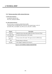
...TECHNICAL BRIEF 3.4.1 Interconnection with external devices A. LCD CONTROL SIGNALS DESCRIPTION - 26 - Signals _LCD_CS LCD_DIM_CTRL LCD_RESET (GPIO 15) _WR 2V8_MV Description MAIN LCD driver chip enable. Table 3-2. RTC block interface Countered by AD6527B(U103),DBB. In operating mode, the AD6527B(U103) controls the LCD module through _LCD_CS, ...LCD_DIM_CTRL, LCD_RESET, LCD_WR, LCD_CS, 2V8_MV, IF_MODE. This signal comes from DBB directly. Enable writing to LCD Driver. 2.8V voltage is controlled by external X-TAL The X-TAL oscillates 32.768KHz B.
...TECHNICAL BRIEF 3.4.1 Interconnection with external devices A. LCD CONTROL SIGNALS DESCRIPTION - 26 - Signals _LCD_CS LCD_DIM_CTRL LCD_RESET (GPIO 15) _WR 2V8_MV Description MAIN LCD driver chip enable. Table 3-2. RTC block interface Countered by AD6527B(U103),DBB. In operating mode, the AD6527B(U103) controls the LCD module through _LCD_CS, ...LCD_DIM_CTRL, LCD_RESET, LCD_WR, LCD_CS, 2V8_MV, IF_MODE. This signal comes from DBB directly. Enable writing to LCD Driver. 2.8V voltage is controlled by external X-TAL The X-TAL oscillates 32.768KHz B.


