Service Manual
Page 4
Incidence of Harm If a telephone company determines that this phone or compatibility with your telecommunications system. If these changes could reasonably be responsible for programming and configuring the equipment to maintain telephone service. Therefore, note ...
Incidence of Harm If a telephone company determines that this phone or compatibility with your telecommunications system. If these changes could reasonably be responsible for programming and configuring the equipment to maintain telephone service. Therefore, note ...
Service Manual
Page 5
...: • Service personnel should ground themselves by using a wrist strap when exchange system boards. • When repairs are for illustrative purposes only; Interference and Attenuation Phone may interfere with sensitive laboratory equipment, medical equipment, etc.Interference from unsuppressed engines or electric motors may look slightly different. Following information is also grounded...
...: • Service personnel should ground themselves by using a wrist strap when exchange system boards. • When repairs are for illustrative purposes only; Interference and Attenuation Phone may interfere with sensitive laboratory equipment, medical equipment, etc.Interference from unsuppressed engines or electric motors may look slightly different. Following information is also grounded...

Service Manual
Page 8
... Stand by Current Talk time Stand by time Charging time RX Sensitivity TX output power GPRS compatibility SIM card type Display Status Indicator ANT EAR Phone Jack PC Synchronization Speech coding Data and Fax Vibrator Loud Speaker Voice Recoding Microphone Speaker/Receiver Travel Adapter MIDI MP3/AAC Options Feature Li-Poly...
... Stand by Current Talk time Stand by time Charging time RX Sensitivity TX output power GPRS compatibility SIM card type Display Status Indicator ANT EAR Phone Jack PC Synchronization Speech coding Data and Fax Vibrator Loud Speaker Voice Recoding Microphone Speaker/Receiver Travel Adapter MIDI MP3/AAC Options Feature Li-Poly...
Service Manual
Page 71
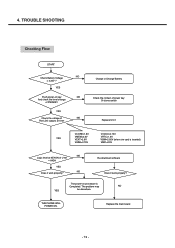
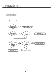
TROUBLE SHOOTING Checking Flow START NO Check Battery Voltage > 3.35V ? Replace the main board - 72 - Re-download software Does it work properly? THE PHONE WILL POWER ON. YES Push power-on procedure is inserted) VMIC=2.5V NO Logic level at U101 Charge or Change Battery Check the contact of ...
TROUBLE SHOOTING Checking Flow START NO Check Battery Voltage > 3.35V ? Replace the main board - 72 - Re-download software Does it work properly? THE PHONE WILL POWER ON. YES Push power-on procedure is inserted) VMIC=2.5V NO Logic level at U101 Charge or Change Battery Check the contact of ...
Service Manual
Page 85
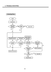
Does it work Properly? YES Voltage at pin1 of NO J301 is 2.85V? NO YES Replace J301 or check soldering of U101 Is 2.85V? YES SIM Card will be detected. NO Does it work Properly? supports only 3V SIM card. YES Change SIM Card Redownload SW. 4. Change the main board - 86 - Our phone supports 2.85V ? YES Voltage at VSIM of components Change the SIM Card NO And try again. TROUBLE SHOOTING Checking Flow START Does the SIM cards NO Change the SIM Card.
Does it work Properly? YES Voltage at pin1 of NO J301 is 2.85V? NO YES Replace J301 or check soldering of U101 Is 2.85V? YES SIM Card will be detected. NO Does it work Properly? supports only 3V SIM card. YES Change SIM Card Redownload SW. 4. Change the main board - 86 - Our phone supports 2.85V ? YES Voltage at VSIM of components Change the SIM Card NO And try again. TROUBLE SHOOTING Checking Flow START Does the SIM cards NO Change the SIM Card.
Service Manual
Page 87
... Replace CN201 Set the audio part of the test Equipment to echo mode Change the earphone and try again Set the audio part of the phone change to PRBS or continuous wave mode NO Can you hear your voice from the earphone? YES Voltage level check Of AUX_SPK_L & AUX_SPK_R signal. TROUBLE...
... Replace CN201 Set the audio part of the test Equipment to echo mode Change the earphone and try again Set the audio part of the phone change to PRBS or continuous wave mode NO Can you hear your voice from the earphone? YES Voltage level check Of AUX_SPK_L & AUX_SPK_R signal. TROUBLE...
Service Manual
Page 103
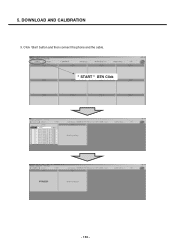
5. DOWNLOAD AND CALIBRATION 3. " START " BTN Click - 104 - Click 'Start' button and then connect the phone and the cable.
5. DOWNLOAD AND CALIBRATION 3. " START " BTN Click - 104 - Click 'Start' button and then connect the phone and the cable.
Service Manual
Page 104
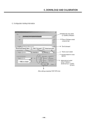
DOWNLOAD AND CALIBRATION C. 5. Configuration Setting Information Download speed (bps ) Start Com port End Com port USE no3.cPhreecsks Start and Wait Model DLL File select (C:\GSMULTI\Model) Phone Software select (mot,m0 file) Donít changed Frame count select ìHermesîselect in case M6100 External boot select (Only TI Model ) (External boot : G7000, G7030 ) After setting completed "OK" BTN click - 105 -
DOWNLOAD AND CALIBRATION C. 5. Configuration Setting Information Download speed (bps ) Start Com port End Com port USE no3.cPhreecsks Start and Wait Model DLL File select (C:\GSMULTI\Model) Phone Software select (mot,m0 file) Donít changed Frame count select ìHermesîselect in case M6100 External boot select (Only TI Model ) (External boot : G7000, G7030 ) After setting completed "OK" BTN click - 105 -
Service Manual
Page 106
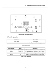
... Power supply Table 5-3 Jig DIP Switch - 107 - It is awaked. DOWNLOAD AND CALIBRATION JTAG2 JTAG1 USB MON PHONE UART TA ON OFF ADI-REMOTE POWER TI-REMOTE TA 1234 POWER ON OFF MON Status PS VBAT + UART Status PS _ Figure 5-3 The top view ..., name is TA-20G(24pin) Table 5-2 Jig Power Switch Number Switch 1 Switch 2 Switch 3 Switch 4 Name ADI-REMOTE TI-REMOTE VBAT PS Description In ON state, phone is used ADI chipset. It is used TI chipset.
... Power supply Table 5-3 Jig DIP Switch - 107 - It is awaked. DOWNLOAD AND CALIBRATION JTAG2 JTAG1 USB MON PHONE UART TA ON OFF ADI-REMOTE POWER TI-REMOTE TA 1234 POWER ON OFF MON Status PS VBAT + UART Status PS _ Figure 5-3 The top view ..., name is TA-20G(24pin) Table 5-2 Jig Power Switch Number Switch 1 Switch 2 Switch 3 Switch 4 Name ADI-REMOTE TI-REMOTE VBAT PS Description In ON state, phone is used ADI chipset. It is used TI chipset.
Service Manual
Page 107
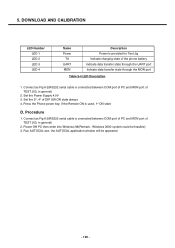
...2000 system could be appeared. - 108 - Connect as Fig 6-2(RS232 serial cable is connected between COM port of PC and MON port of the phone battery Indicate data transfer state through the UART port Indicate data transfer state through the MON port Table 5-4 LED Description 1. Set the 3rd, 4th of... TEST JIG, in general) 2. Set the Power Supply 4.0V 3. Press the Phone power key, if the Remote ON is provided for Test Jig Indicate charging state of TEST JIG, in general) 2. Connect as Fig 6-2(RS232 serial cable...
...2000 system could be appeared. - 108 - Connect as Fig 6-2(RS232 serial cable is connected between COM port of PC and MON port of the phone battery Indicate data transfer state through the UART port Indicate data transfer state through the MON port Table 5-4 LED Description 1. Set the 3rd, 4th of... TEST JIG, in general) 2. Set the Power Supply 4.0V 3. Press the Phone power key, if the Remote ON is provided for Test Jig Indicate charging state of TEST JIG, in general) 2. Connect as Fig 6-2(RS232 serial cable...
Service Manual
Page 110
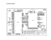
... Designer Checked Date 09/02 2005 Approved Sign & Name MODEL M6100 (X1) Sheet/Sheets 1 / 7 DRAWING Hermes 6527B / TyphoonB 6535 NAME LG Electronics Inc. CIRCUIT DIAGRAM 1 2 3 4 5 6 7 8 9 10 1V8_VCORE 2V8_VMEM 2V8_VEXT 2V8_VMEM 2V85_VSIM VUSB 1V8_VRTC Speaker Phone Pwr D101 RPWRON R106 100K 2 3 1 KDR331V ONNOFF PWRON ...PA_BAND PCM_EN S_EN S_DATA S_CLK BATT_TEMP USB+ USB- DRAWING NO. Notice No. REV.1.1 1 2 3 4 5 LGIC(42)-A-5505-10:01 LG Electronics Inc. - 111 - C133 1u C134 1u C139 1u R113 82K (1%) TP109 C146 0.1u H1 H2 CSDO CSDI L2 G2 CSFS F1...
... Designer Checked Date 09/02 2005 Approved Sign & Name MODEL M6100 (X1) Sheet/Sheets 1 / 7 DRAWING Hermes 6527B / TyphoonB 6535 NAME LG Electronics Inc. CIRCUIT DIAGRAM 1 2 3 4 5 6 7 8 9 10 1V8_VCORE 2V8_VMEM 2V8_VEXT 2V8_VMEM 2V85_VSIM VUSB 1V8_VRTC Speaker Phone Pwr D101 RPWRON R106 100K 2 3 1 KDR331V ONNOFF PWRON ...PA_BAND PCM_EN S_EN S_DATA S_CLK BATT_TEMP USB+ USB- DRAWING NO. Notice No. REV.1.1 1 2 3 4 5 LGIC(42)-A-5505-10:01 LG Electronics Inc. - 111 - C133 1u C134 1u C139 1u R113 82K (1%) TP109 C146 0.1u H1 H2 CSDO CSDI L2 G2 CSFS F1...

Service Manual
Page 125
... EL Backlight. 1) Backlight on : LCD Backlight and Keypad EL Backlight light on . 2) Vibrator off : Vibration mode is off at last will be saved in the phone is to adjust the level of Backlight.
... EL Backlight. 1) Backlight on : LCD Backlight and Keypad EL Backlight light on . 2) Vibrator off : Vibration mode is off at last will be saved in the phone is to adjust the level of Backlight.
Service Manual
Page 126
... displays the value of Temperature Calibration. Although the actual value can be written over, it returns to default value after switching off and on the phone. 1) VbControl1 : VbControl1 bit Register Value Setting 2) VbControl2 : VbControl2 bit Register Value Setting 3) VbControl3 : VbControl3 bit Register Value Setting 4) VbControl4 : VbControl4 bit Register Value Setting 5) VbControl5...
... displays the value of Temperature Calibration. Although the actual value can be written over, it returns to default value after switching off and on the phone. 1) VbControl1 : VbControl1 bit Register Value Setting 2) VbControl2 : VbControl2 bit Register Value Setting 3) VbControl3 : VbControl3 bit Register Value Setting 4) VbControl4 : VbControl4 bit Register Value Setting 5) VbControl5...
Service Manual
Page 127
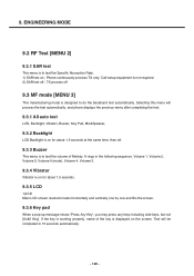
...-up message shows 'Press Any Key', you may press any keys including side keys, but not [Soft2 Key]. Test will process the test automatically, and phone displays the previous menu after completing the test. 9.3.1 All auto test LCD, Backlight, Vibrator, Buzzer, Key Pad, Mic&Speaker, 9.3.2 Backlight LCD Backlight is on for... is to do the baseband test automatically. Call-setup equipment is not required. 2) SAR test off : TX process off . 9.3.3 Buzzer This menu is displayed on : Phone continuously process TX only.
...-up message shows 'Press Any Key', you may press any keys including side keys, but not [Soft2 Key]. Test will process the test automatically, and phone displays the previous menu after completing the test. 9.3.1 All auto test LCD, Backlight, Vibrator, Buzzer, Key Pad, Mic&Speaker, 9.3.2 Backlight LCD Backlight is on for... is to do the baseband test automatically. Call-setup equipment is not required. 2) SAR test off : TX process off . 9.3.3 Buzzer This menu is displayed on : Phone continuously process TX only.
Service Manual
Page 128
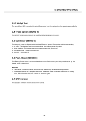
... valuable data such as Setting value, RF Calibration data, etc. Reset [MENU 6] This Factory Reset menu is to set up the default value in the phone. - 129 - Reset (i.e.Factory Reset) should NOT progress this , [00:00:00]. 3) DAI DOWNLINK : Speech decoder test 4) DAI OFF : DAI mode off 9.6 Fact. ENGINEERING MODE 9.3.7 MicSpk...
... valuable data such as Setting value, RF Calibration data, etc. Reset [MENU 6] This Factory Reset menu is to set up the default value in the phone. - 129 - Reset (i.e.Factory Reset) should NOT progress this , [00:00:00]. 3) DAI DOWNLINK : Speech decoder test 4) DAI OFF : DAI mode off 9.6 Fact. ENGINEERING MODE 9.3.7 MicSpk...
Service Manual
Page 129
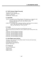
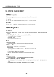
...Power level - Scaling Factor - b. Leave the rest as explained below. - Select either Power level or Scaling Factor. See if the value of the phones is activating normally. 10.2 Setting Method A. this is to see if the transmitter of RSSI is close to -16dBm when setting the value between 0~15...of GSM or DCS Band and input appropriate channel. 2. In the "Dialog Menu", select the values as default values B. 10. B. C. Normal phone should indicate the value of GSM or DCS Band and input appropriate channel. 2. Select one of the mouse and select "Com setting". You may ...
...Power level - Scaling Factor - b. Leave the rest as explained below. - Select either Power level or Scaling Factor. See if the value of the phones is activating normally. 10.2 Setting Method A. this is to see if the transmitter of RSSI is close to -16dBm when setting the value between 0~15...of GSM or DCS Band and input appropriate channel. 2. In the "Dialog Menu", select the values as default values B. 10. B. C. Normal phone should indicate the value of GSM or DCS Band and input appropriate channel. 2. Select one of the mouse and select "Com setting". You may ...
Service Manual
Page 132
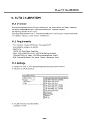
... Willtec M44XX(Call Setting Instrument) - Tektronix PS2521G or Agilent 66311B(Programmable Power Supply) - PC or Notebook installed with phone and measuring equipment then write it into calibration data block of flash memory in GSM phone. 11.2 Requirements - 11. Auto Calibration program (Hot_kimchi) - Equipment Setup) 11.3 Settings 1. Create a new folder as below after...
... Willtec M44XX(Call Setting Instrument) - Tektronix PS2521G or Agilent 66311B(Programmable Power Supply) - PC or Notebook installed with phone and measuring equipment then write it into calibration data block of flash memory in GSM phone. 11.2 Requirements - 11. Auto Calibration program (Hot_kimchi) - Equipment Setup) 11.3 Settings 1. Create a new folder as below after...
Service Manual
Page 134
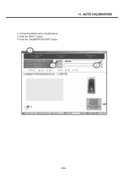
Push the "APPLY" button. 4. AUTO CALIBRATION - 135 - Push the "CALIBRATION START" button. 11. 2. Choose the Model name of mobile phone. 3.
Push the "APPLY" button. 4. AUTO CALIBRATION - 135 - Push the "CALIBRATION START" button. 11. 2. Choose the Model name of mobile phone. 3.
Service Manual
Page 135
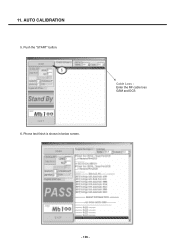
Push the "START" button. Cable Loss : Enter the RF cable loss GSM and DCS 6. Phone test finish is shown in below screen. - 136 - AUTO CALIBRATION 5. 11.
Push the "START" button. Cable Loss : Enter the RF cable loss GSM and DCS 6. Phone test finish is shown in below screen. - 136 - AUTO CALIBRATION 5. 11.
Service Manual
Page 138
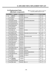
Description GSM(SLIDE) 2 AAAY00 ADDITION 2 APEY00 PHONE 3 ABGA00 BUTTON ASSY,DIAL 3 ACGM00 COVER ASSY,REAR 4 MCCC00 CAP,EARPHONE JACK 4 MCCE00 CAP,RECEPTACLE 4 MCJN00 COVER,REAR 4 MHGB00 ...MTAZ00 TAPE 5 MTAZ01 TAPE 4 ACGR00 COVER ASSY, SLIDE(LOWER) 5 MCJV00 COVER,SLIDE(LOWER) 5 MDAD00 DECO,CAMERA Part Number Specification TGLL0002601 AAAY0138001 M6100 EUASV APEY0243601 ABGA0005601 BUTTON ASSY,DIAL (MAIN), ENGLISH ACGM0061701 MCCC0029301 MCCE0023201 MCJN0044901 MHGB0001701 MIDZ0081101 17.4*14*0.05 MLEA0026401 MSDC0001301 C1300 CGRSV Cone Type 1.8PI, ...
Description GSM(SLIDE) 2 AAAY00 ADDITION 2 APEY00 PHONE 3 ABGA00 BUTTON ASSY,DIAL 3 ACGM00 COVER ASSY,REAR 4 MCCC00 CAP,EARPHONE JACK 4 MCCE00 CAP,RECEPTACLE 4 MCJN00 COVER,REAR 4 MHGB00 ...MTAZ00 TAPE 5 MTAZ01 TAPE 4 ACGR00 COVER ASSY, SLIDE(LOWER) 5 MCJV00 COVER,SLIDE(LOWER) 5 MDAD00 DECO,CAMERA Part Number Specification TGLL0002601 AAAY0138001 M6100 EUASV APEY0243601 ABGA0005601 BUTTON ASSY,DIAL (MAIN), ENGLISH ACGM0061701 MCCC0029301 MCCE0023201 MCJN0044901 MHGB0001701 MIDZ0081101 17.4*14*0.05 MLEA0026401 MSDC0001301 C1300 CGRSV Cone Type 1.8PI, ...


