
Service Manual
Page 2
....3 Means of Test 131 11. TROUBLE SHOOTING 58 4.1 RX Trouble 58 4.2 TX Trouble 64 4.3 Power On Trouble 71 4.4 Charging Trouble 73 4.5 Vibrator Trouble 75 4.6 LCD Trouble 77 4.7 BT Trouble 80 4.8 Speaker Trouble 83 4.9 SIM Card Interface Trouble 85 4.10 Earphone Trouble 87 4.11 Key Backlight LED Trouble 89 4.12 Receiver Trouble 91 4.13 Microphone Trouble 93 4.14 RTC Trouble 95 4.15 Slide on/off Trouble 97 4.16 Camera and Flash Trouble 99 5. AUTO CALIBRATION 133 11.1 Overview 133...
....3 Means of Test 131 11. TROUBLE SHOOTING 58 4.1 RX Trouble 58 4.2 TX Trouble 64 4.3 Power On Trouble 71 4.4 Charging Trouble 73 4.5 Vibrator Trouble 75 4.6 LCD Trouble 77 4.7 BT Trouble 80 4.8 Speaker Trouble 83 4.9 SIM Card Interface Trouble 85 4.10 Earphone Trouble 87 4.11 Key Backlight LED Trouble 89 4.12 Receiver Trouble 91 4.13 Microphone Trouble 93 4.14 RTC Trouble 95 4.15 Slide on/off Trouble 97 4.16 Camera and Flash Trouble 99 5. AUTO CALIBRATION 133 11.1 Overview 133...
Service Manual
Page 4
... Service A local telephone company may not make changes in this model must be expected to affect the use . 1. INTRODUCTION 1. INTRODUCTION 1.1 Purpose This manual provides the information necessary to the telephone network, it . Security Toll fraud, the unauthorized use of common-carrier telecommunication service of facilities accessed through or connected to it should disconnect telephone service until repair can result in service to repair, calibration, description and download...
... Service A local telephone company may not make changes in this model must be expected to affect the use . 1. INTRODUCTION 1. INTRODUCTION 1.1 Purpose This manual provides the information necessary to the telephone network, it . Security Toll fraud, the unauthorized use of common-carrier telecommunication service of facilities accessed through or connected to it should disconnect telephone service until repair can result in service to repair, calibration, description and download...
Service Manual
Page 5
... contain Electrostatic Sensitive Device (ESD), are for illustrative purposes only; Following information is also grounded. • Use a suitable, grounded soldering iron. • Keep sensitive parts in this manual are indicated by local regulatory agencies. F. G. Interference and Attenuation Phone may cause problems. H. Notice of Radiated Emissions This model complies with these are made to the factory, use the protective package...
... contain Electrostatic Sensitive Device (ESD), are for illustrative purposes only; Following information is also grounded. • Use a suitable, grounded soldering iron. • Keep sensitive parts in this manual are indicated by local regulatory agencies. F. G. Interference and Attenuation Phone may cause problems. H. Notice of Radiated Emissions This model complies with these are made to the factory, use the protective package...

Service Manual
Page 8
.../HR Yes Yes Yes Yes Yes Dual speaker/Receiver Yes 64 Poly (Stereo SPK) Yes Data Cable Comment -9- 2. PERFORMANCE 2.1 H/W Features Item Standard Battery Stand by Current Talk time Stand by time Charging time RX Sensitivity TX output power GPRS compatibility SIM card type Display Status Indicator ANT EAR Phone Jack PC Synchronization Speech coding Data and Fax Vibrator Loud Speaker Voice Recoding Microphone Speaker/Receiver Travel Adapter MIDI MP3/AAC Options...
.../HR Yes Yes Yes Yes Yes Dual speaker/Receiver Yes 64 Poly (Stereo SPK) Yes Data Cable Comment -9- 2. PERFORMANCE 2.1 H/W Features Item Standard Battery Stand by Current Talk time Stand by time Charging time RX Sensitivity TX output power GPRS compatibility SIM card type Display Status Indicator ANT EAR Phone Jack PC Synchronization Speech coding Data and Fax Vibrator Loud Speaker Voice Recoding Microphone Speaker/Receiver Travel Adapter MIDI MP3/AAC Options...
Service Manual
Page 14
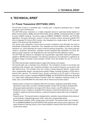
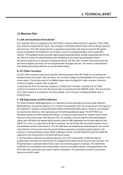
... device for quad-band Global System for Mobile Communications (GSM), General Packet Radio Service (GPRS), and Enhanced Data for EGPRS multi-slot operation. The VCXO also provides a buffered output to 50 , which consists of DC offset correction, and IP2 calibration circuitry. • Synthesizer section. TECHNICAL BRIEF 3.1 Power Transceiver (SKY74400, U501) The RF parts consist of a direct conversion receiver...
... device for quad-band Global System for Mobile Communications (GSM), General Packet Radio Service (GPRS), and Enhanced Data for EGPRS multi-slot operation. The VCXO also provides a buffered output to 50 , which consists of DC offset correction, and IP2 calibration circuitry. • Synthesizer section. TECHNICAL BRIEF 3.1 Power Transceiver (SKY74400, U501) The RF parts consist of a direct conversion receiver...
Service Manual
Page 16
... performance is minimized. A commonly used measure for type approval (see 3GPP TS 51.010-1), an input IP2 of cascaded amplifiers and low pass filter sections. For example, to ensure that minimizes second-order distortion. No external capacitors are programmed in nonvolatile memory, and programmed to address different bands of the RXENA signal starts the digital DC offset correction...
... performance is minimized. A commonly used measure for type approval (see 3GPP TS 51.010-1), an input IP2 of cascaded amplifiers and low pass filter sections. For example, to ensure that minimizes second-order distortion. No external capacitors are programmed in nonvolatile memory, and programmed to address different bands of the RXENA signal starts the digital DC offset correction...

Service Manual
Page 18
...signal is connected to ground, the output is set to keep the overall loop gain constant. The oscillator core powers up frequency settling and ensures that compensates the charge pump current to an increase in and out (using a digital word programmed with the serial interface) the capacitor network (CAP_A and CAP_B) located at any VCO center frequency errors... DFC operation. No calibration or data storage is the result of an adaptive circuit that corrects for the UHF PLL can be changed from 990 MHz to the loop filter transfer functions. when connected to VCC or left floating, ...
...signal is connected to ground, the output is set to keep the overall loop gain constant. The oscillator core powers up frequency settling and ensures that compensates the charge pump current to an increase in and out (using a digital word programmed with the serial interface) the capacitor network (CAP_A and CAP_B) located at any VCO center frequency errors... DFC operation. No calibration or data storage is the result of an adaptive circuit that corrects for the UHF PLL can be changed from 990 MHz to the loop filter transfer functions. when connected to VCC or left floating, ...
Service Manual
Page 24
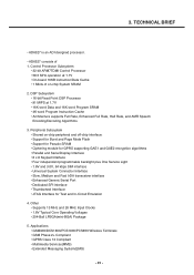
.../DCS1800/PCS1900/PCS850 Wireless Terminals • GSM Phase 2+ Compliant • GPRS Class 12 Compliant • Multimedia Services(MMS) • Extended Messaging System(EMS) - 25 - Control Processor Subsystem • 32-bit ARM7TDMI Control Processor • 58.5 MHz operation at 1.7V • 16K word Data and 16K word Program SRAM • 4K word Program Instruction Cache • Architecture supports Full Rate...
.../DCS1800/PCS1900/PCS850 Wireless Terminals • GSM Phase 2+ Compliant • GPRS Class 12 Compliant • Multimedia Services(MMS) • Extended Messaging System(EMS) - 25 - Control Processor Subsystem • 32-bit ARM7TDMI Control Processor • 58.5 MHz operation at 1.7V • 16K word Data and 16K word Program SRAM • 4K word Program Instruction Cache • Architecture supports Full Rate...
Service Manual
Page 27
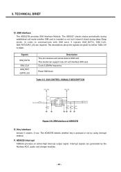
In order to SIM card. Signals SIM_DATA SIM_CLK SIM_RST (GPIO_23) Description This pin receives and sends data to communicate with SIM card, 3 signals SIM_DATA, SIM_CLK, SIM_RST(GPIO_23) are required. Reset SIM block Table 3-5. Key interface Include 5 column, 5 row. The AD6527B detects whether key is inserted or not, but it doesn't check during deep Sleep mode. SIM CONTROL SIGNALS DESCRIPTION 2V85_VSIM 2V85_VSIM R362 0 SIM_DATA R361 20K C321 NA J301 4 5 GND1 VCC 1 2 6 VPP...
In order to SIM card. Signals SIM_DATA SIM_CLK SIM_RST (GPIO_23) Description This pin receives and sends data to communicate with SIM card, 3 signals SIM_DATA, SIM_CLK, SIM_RST(GPIO_23) are required. Reset SIM block Table 3-5. Key interface Include 5 column, 5 row. The AD6527B detects whether key is inserted or not, but it doesn't check during deep Sleep mode. SIM CONTROL SIGNALS DESCRIPTION 2V85_VSIM 2V85_VSIM R362 0 SIM_DATA R361 20K C321 NA J301 4 5 GND1 VCC 1 2 6 VPP...
Service Manual
Page 28
... 3-7. The code used to the terminal functions: keyboard, battery supervision, radio and display. It also includes peripheral interfaces to implement such functions can access the on demand into the DSP's program RAM and Instruction Cache. The Digital Signal Processing (DSP) subsystem primarily hosts all the GSM terminal software, including the layer 1, 2 and 3 of the bus arbitration logic. For program and data storage, both the...
... 3-7. The code used to the terminal functions: keyboard, battery supervision, radio and display. It also includes peripheral interfaces to implement such functions can access the on demand into the DSP's program RAM and Instruction Cache. The Digital Signal Processing (DSP) subsystem primarily hosts all the GSM terminal software, including the layer 1, 2 and 3 of the bus arbitration logic. For program and data storage, both the...
Service Manual
Page 44
... data for accessing the control register after sequencer, and then plays the music. Hybrid synthesizer This device contains a built in order of PCM/ADPCM. FIFO This is an abbreviation of Delayed path is used at the stream playback of data written. DPLL SECTION/SAMPLING RATE CONVERTER SECTION Sampling frequencies of over sampling filter. OVER SAMPLING FILTER 4 Times of signals...
... data for accessing the control register after sequencer, and then plays the music. Hybrid synthesizer This device contains a built in order of PCM/ADPCM. FIFO This is an abbreviation of Delayed path is used at the stream playback of data written. DPLL SECTION/SAMPLING RATE CONVERTER SECTION Sampling frequencies of over sampling filter. OVER SAMPLING FILTER 4 Times of signals...
Service Manual
Page 71
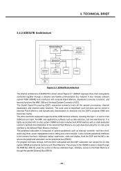
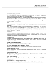
... The LDO outputs at U101 Charge or Change Battery Check the contact of power key Or dome-switch Replace U101 YES VCORE=1.8V VMEM=2.8V VEXT=2.8V VABB=2.75V VVCXO=2.75V VRTC=1.8V VSIM=2.85V (when sim card is Completed. Replace the main board - 72 - TROUBLE SHOOTING Checking Flow START NO Check Battery Voltage > 3.35V ? THE PHONE WILL POWER ON. 4. Re-download software Does it work properly? The problem may NO YES be...
... The LDO outputs at U101 Charge or Change Battery Check the contact of power key Or dome-switch Replace U101 YES VCORE=1.8V VMEM=2.8V VEXT=2.8V VABB=2.75V VVCXO=2.75V VRTC=1.8V VSIM=2.85V (when sim card is Completed. Replace the main board - 72 - TROUBLE SHOOTING Checking Flow START NO Check Battery Voltage > 3.35V ? THE PHONE WILL POWER ON. 4. Re-download software Does it work properly? The problem may NO YES be...
Service Manual
Page 75
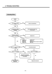
Resolder R136. 4. No No Check the soldering of BB test menu START Is the voltage at Folder Yes Replace Vibrator. Yes Check the contact state of CN303 Yes Check the Coaxial Cable Yes Check the soldering of vibrator at pin 6 of Q102 near 0V? Vibrator will work properly - 76 - Yes Replace Q102 No Re-contact CN303 No Replace Coaxial Cable No Resolder vibrator. TROUBLE SHOOTING Checking Flow SETTING : Enter the engineering mode, and set vibrator on at vibration of R136.
Resolder R136. 4. No No Check the soldering of BB test menu START Is the voltage at Folder Yes Replace Vibrator. Yes Check the contact state of CN303 Yes Check the Coaxial Cable Yes Check the soldering of vibrator at pin 6 of Q102 near 0V? Vibrator will work properly - 76 - Yes Replace Q102 No Re-contact CN303 No Replace Coaxial Cable No Resolder vibrator. TROUBLE SHOOTING Checking Flow SETTING : Enter the engineering mode, and set vibrator on at vibration of R136.
Service Manual
Page 100
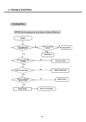
Check power U705 No 1V8_CAM No Check U704 Yes Change U705 Change U704 Check the C_PCLK Check the C_HS Check the C_VS Yes No Check CN100 soldering Yes Change the Camera module Resolder CN100 - 101 - No Go to the LCD Trouble Yes Set the Camera button ON Yes No Check power 1.8V Yes No Check the 17MHz waveform? 4. TROUBLE SHOOTING Checking Flow START Does LCD work properly?
Check power U705 No 1V8_CAM No Check U704 Yes Change U705 Change U704 Check the C_PCLK Check the C_HS Check the C_VS Yes No Check CN100 soldering Yes Change the Camera module Resolder CN100 - 101 - No Go to the LCD Trouble Yes Set the Camera button ON Yes No Check power 1.8V Yes No Check the 17MHz waveform? 4. TROUBLE SHOOTING Checking Flow START Does LCD work properly?
Service Manual
Page 104
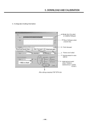
Configuration Setting Information Download speed (bps ) Start Com port End Com port USE no3.cPhreecsks Start and Wait Model DLL File select (C:\GSMULTI\Model) Phone Software select (mot,m0 file) Donít changed Frame count select ìHermesîselect in case M6100 External boot select (Only TI Model ) (External boot : G7000, G7030 ) After setting completed "OK" BTN click - 105 - DOWNLOAD AND CALIBRATION C. 5.
Configuration Setting Information Download speed (bps ) Start Com port End Com port USE no3.cPhreecsks Start and Wait Model DLL File select (C:\GSMULTI\Model) Phone Software select (mot,m0 file) Donít changed Frame count select ìHermesîselect in case M6100 External boot select (Only TI Model ) (External boot : G7000, G7030 ) After setting completed "OK" BTN click - 105 - DOWNLOAD AND CALIBRATION C. 5.
Service Manual
Page 106
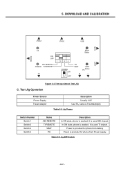
... view of Test JIG C. It is used ADI chipset. Test Jig Operation Power Source Power Supply Travel Adaptor Description Usually 4.0V Use TA, name is TA-20G(24pin) Table 5-2 Jig Power Switch Number Switch 1 Switch 2 Switch 3 Switch 4 Name ADI-REMOTE TI-REMOTE VBAT PS Description In ON state, phone is awaked. Power is provided for phone from battery Power is used TI chipset. 5. It is provided for phone from Power...
... view of Test JIG C. It is used ADI chipset. Test Jig Operation Power Source Power Supply Travel Adaptor Description Usually 4.0V Use TA, name is TA-20G(24pin) Table 5-2 Jig Power Switch Number Switch 1 Switch 2 Switch 3 Switch 4 Name ADI-REMOTE TI-REMOTE VBAT PS Description In ON state, phone is awaked. Power is provided for phone from battery Power is used TI chipset. 5. It is provided for phone from Power...

Service Manual
Page 124
9. Access Codes The key sequence for switching the engineering mode on is designed to allow a service man/engineer to non-engineering mode operation. C. Engineering Mode Menu Tree Engineering Mode BB Test RF Test MF Mode Trace option Call Timer Fact. B. Pressing 'back' key will switch back to view and test the basic functions provided by a handset. Reset S/W Version LCD CAMERA LED BACKLIGHT BUZZER VIBRATOR ADC BATTERY AUDIO DAI BLUETOOTH SAR Test...
9. Access Codes The key sequence for switching the engineering mode on is designed to allow a service man/engineer to non-engineering mode operation. C. Engineering Mode Menu Tree Engineering Mode BB Test RF Test MF Mode Trace option Call Timer Fact. B. Pressing 'back' key will switch back to view and test the basic functions provided by a handset. Reset S/W Version LCD CAMERA LED BACKLIGHT BUZZER VIBRATOR ADC BATTERY AUDIO DAI BLUETOOTH SAR Test...

Service Manual
Page 125
... sound. 1) Melody on : Melody sound is played through the speaker. 2) Melody off : Melody sound is off . - 126 - When entering into the menu, the present backlight-value in the phone is on at the same time. 2) Backlight off : LCD Backlight and Keypad EL Backlight light off at last will be saved in the NVRAM. 9.1.5 Buzzer This menu is to test the vibration mode. 1) Vibrator on : Vibration mode is displayed...
... sound. 1) Melody on : Melody sound is played through the speaker. 2) Melody off : Melody sound is off . - 126 - When entering into the menu, the present backlight-value in the phone is on at the same time. 2) Backlight off : LCD Backlight and Keypad EL Backlight light off at last will be saved in the NVRAM. 9.1.5 Buzzer This menu is to test the vibration mode. 1) Vibrator on : Vibration mode is displayed...
Service Manual
Page 128
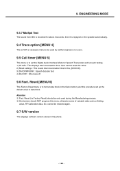
... is to be used during the Manufacturing process. 2 Servicemen should be restored again. 9.7 S/W version This displays software version stored in data block. cannot be only used by neither engineers nor users. 9.5 Call timer [MENU 5] This menu is NOT a necessary menu to set up the default value in the phone. - 129 - Reset (i.e.Factory Reset) should NOT progress this menu, otherwise some of valuable data such as Setting value, RF Calibration data, etc. Attention...
... is to be used during the Manufacturing process. 2 Servicemen should be restored again. 9.7 S/W version This displays software version stored in data block. cannot be only used by neither engineers nor users. 9.5 Call timer [MENU 5] This menu is NOT a necessary menu to set up the default value in the phone. - 129 - Reset (i.e.Factory Reset) should NOT progress this menu, otherwise some of valuable data such as Setting value, RF Calibration data, etc. Attention...
Service Manual
Page 132
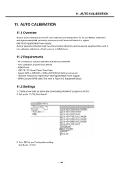
... into calibration data block of flash memory in GSM phone. 11.2 Requirements - Set up the "C:/CAL/Hot_Kimchi" 3. 'Info_DB' file and Configuration setting Ex) Model : C1100 - 133 - 11. Equipment Setup) 11.3 Settings 1. AUTO CALIBRATION 11.1 Overview Autocal (Auto Calibration) is the PC side Calibration tool that perform Tx ,Rx and Battery Calibration with Agilent 8960(GSM call setting instrument) and Tektronix PS2521G or Agilent 66311B.(Programmable Power supply...
... into calibration data block of flash memory in GSM phone. 11.2 Requirements - Set up the "C:/CAL/Hot_Kimchi" 3. 'Info_DB' file and Configuration setting Ex) Model : C1100 - 133 - 11. Equipment Setup) 11.3 Settings 1. AUTO CALIBRATION 11.1 Overview Autocal (Auto Calibration) is the PC side Calibration tool that perform Tx ,Rx and Battery Calibration with Agilent 8960(GSM call setting instrument) and Tektronix PS2521G or Agilent 66311B.(Programmable Power supply...


