

Service Manual
Page 2
... ...4 Safety Precautions...5 Dimensions...11 Indoor Unit...11 Outdoor Unit ...12 Product Specifications ...13 Installation ...15 Installation Parts...15 Installation Tools...15 Select the best location ...16 Piping length and elevation ...17 Fixing Installation Plate(Standart Type 18 Preparing work for Installation (Artcool Type Only 19 Flaring Work and Connection of Piping 21 Flaring work...21...
... ...4 Safety Precautions...5 Dimensions...11 Indoor Unit...11 Outdoor Unit ...12 Product Specifications ...13 Installation ...15 Installation Parts...15 Installation Tools...15 Select the best location ...16 Piping length and elevation ...17 Fixing Installation Plate(Standart Type 18 Preparing work for Installation (Artcool Type Only 19 Flaring Work and Connection of Piping 21 Flaring work...21...
Service Manual
Page 5
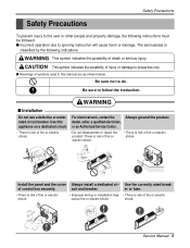
...only. WARNING This symbol indicates the possibility of fire or electric shock. • Do not disassemble or repair the product. WARNING s Installation Do not use a defective or under- For electrical work, contact the Always ground the product. or an Authorized Service Center. •... the following indications. Use the correctly rated break- Be sure not to follow the instruction. rated circuit breaker. Install the panel and the cover Always install a dedicated cir- The seriousness is risk of fire or electric cause fire or electric shock shock. s Incorrect operation...
...only. WARNING This symbol indicates the possibility of fire or electric shock. • Do not disassemble or repair the product. WARNING s Installation Do not use a defective or under- For electrical work, contact the Always ground the product. or an Authorized Service Center. •... the following indications. Use the correctly rated break- Be sure not to follow the instruction. rated circuit breaker. Install the panel and the cover Always install a dedicated cir- The seriousness is risk of fire or electric cause fire or electric shock shock. s Incorrect operation...
Service Manual
Page 6
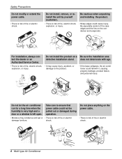
... unit by yourself (customer). • There is risk of fire, electric shock, explosion, or injury. Be cautious when unpacking and installing the product. • Sharp edges could not be pulled out or damaged during operation. • Moisture may cause injury, accident,...edges and the fins on a Be sure the installation area defective installation stand. does not deteriorate with it, causing property damage, product failure, and personal injury. Do not install the product on the condenser and evaporator. For installation, always contact the dealer or an Authorized Service ...
... unit by yourself (customer). • There is risk of fire, electric shock, explosion, or injury. Be cautious when unpacking and installing the product. • Sharp edges could not be pulled out or damaged during operation. • Moisture may cause injury, accident,...edges and the fins on a Be sure the installation area defective installation stand. does not deteriorate with it, causing property damage, product failure, and personal injury. Do not install the product on the condenser and evaporator. For installation, always contact the dealer or an Authorized Service ...
Service Manual
Page 8
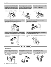
...the main power off the breaker. water is not be used for gas (refrigerant) leak- leakage. When the product is drained away properly. age. Install the drain hose to ensure that nobody could step on connect the power supply plug or turn off when cleaning or maintaining the product. • ... of fire or electric shock. • There is risk of product. Ventilate the product from time to ensure that Keep level even when age after installation or repair of product. Take care to time when operating it together with a stove, etc. • There is risk of product damage or failure,...
...the main power off the breaker. water is not be used for gas (refrigerant) leak- leakage. When the product is drained away properly. age. Install the drain hose to ensure that nobody could step on connect the power supply plug or turn off when cleaning or maintaining the product. • ... of fire or electric shock. • There is risk of product. Ventilate the product from time to ensure that Keep level even when age after installation or repair of product. Take care to time when operating it together with a stove, etc. • There is risk of product damage or failure,...
Service Manual
Page 9
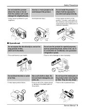
...cause corrosion on the condenser and evaporator fins, could cause product malfunction or inefficient operation. Wax Thinner Service Manual 9 Safety Precautions Do not install the product where the noise or hot air from the outdoor unit could damage the neighborhoods. • It may cause a problem for your... foods, works of air flow. Corrosion, particularly on the product. Do not use the product for long periods of personal injury. Do not install the product where it will be exposed to sea wind (salt spray) directly. • Avoid personal injury. • It may cause product...
...cause corrosion on the condenser and evaporator fins, could cause product malfunction or inefficient operation. Wax Thinner Service Manual 9 Safety Precautions Do not install the product where the noise or hot air from the outdoor unit could damage the neighborhoods. • It may cause a problem for your... foods, works of air flow. Corrosion, particularly on the product. Do not use the product for long periods of personal injury. Do not install the product where it will be exposed to sea wind (salt spray) directly. • Avoid personal injury. • It may cause product...

Service Manual
Page 11
Dimensions Indoor Unit 1. Art Cool Type Indoor Unit W D H Pipe Hole Hanger Hole Installation plate Fix Hole Dimension W H D Model mm mm mm Split Type S4 SE 9 kBtu/h 12 kBtu/h 840 895 270 282 153 165 ARTCOOL Type SP3 9 kBtu/h 12 kBtu/h 570 568 129 Service Manual 11 Split Type Indoor H D W Dimensions 2.
Dimensions Indoor Unit 1. Art Cool Type Indoor Unit W D H Pipe Hole Hanger Hole Installation plate Fix Hole Dimension W H D Model mm mm mm Split Type S4 SE 9 kBtu/h 12 kBtu/h 840 895 270 282 153 165 ARTCOOL Type SP3 9 kBtu/h 12 kBtu/h 570 568 129 Service Manual 11 Split Type Indoor H D W Dimensions 2.
Service Manual
Page 14
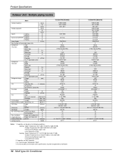
....6 (870*1060*320) 80(176) 45 15 7.5 7.5 41.1*44.9*17.3 (1045*1140*440) 51/111 Installation Indoor Unit~Outdoor Unit m Height Difference Indoor Unit~Indoor Unit m Packing Dimension W*H*D inch(mm) Stuffing Quantity 20/40ft A3UC363FA0(LMU360CE) 9,000~36,000 2637~10,550 2267~9071 1320~3680 5.9~16.6 1,208/230,60 3 Rotary GK141K...
....6 (870*1060*320) 80(176) 45 15 7.5 7.5 41.1*44.9*17.3 (1045*1140*440) 51/111 Installation Indoor Unit~Outdoor Unit m Height Difference Indoor Unit~Indoor Unit m Packing Dimension W*H*D inch(mm) Stuffing Quantity 20/40ft A3UC363FA0(LMU360CE) 9,000~36,000 2637~10,550 2267~9071 1320~3680 5.9~16.6 1,208/230,60 3 Rotary GK141K...
Service Manual
Page 15
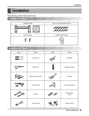
Installation Read carefully, and then follow step by step. Installation Parts Installation plate Type "B" screw Installation Type "A" screw and plastic anchor Remote Control Holder Installation Tools Figure Name Screw driver Electric Drill Measuring Tape, Knife Hole Core Drill Spanner Torque wrench Figure Name Ohmmeter Hexagonal wrench Ammeter Gas Leak Detector Thermometer, Level Flaring Tool Set Service Manual 15
Installation Read carefully, and then follow step by step. Installation Parts Installation plate Type "B" screw Installation Type "A" screw and plastic anchor Remote Control Holder Installation Tools Figure Name Screw driver Electric Drill Measuring Tape, Knife Hole Core Drill Spanner Torque wrench Figure Name Ohmmeter Hexagonal wrench Ammeter Gas Leak Detector Thermometer, Level Flaring Tool Set Service Manual 15
Service Manual
Page 16
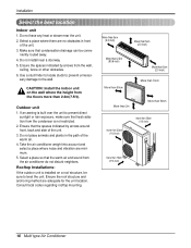
...(27.6 inch) 16 Multi type Air Conditioner sary damage to prevent unneces- If an awning is installed on the wall where the height from the condenser is not restricted. 2. Rooftop Installations: If the outdoor unit is built over the unit to level the unit. Select a place where..., make sure that the warm air and sound from the wall, ceiling, fence or other obstacles. 6. Installation Select the best location Indoor unit 1. Do not install near the unit. 2. CAUTION: Install the indoor unit on a roof structure, be conve- Take the air conditioner weight into account and select ...
...(27.6 inch) 16 Multi type Air Conditioner sary damage to prevent unneces- If an awning is installed on the wall where the height from the condenser is not restricted. 2. Rooftop Installations: If the outdoor unit is built over the unit to level the unit. Select a place where..., make sure that the warm air and sound from the wall, ceiling, fence or other obstacles. 6. Installation Select the best location Indoor unit 1. Do not install near the unit. 2. CAUTION: Install the indoor unit on a roof structure, be conve- Take the air conditioner weight into account and select ...
Service Manual
Page 17
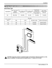
Service Manual 17 Oil trap should be installed every 5~7 meters (16.4~23.0ft). Installation Piping length and elevation Multi Piping Type Capacity(Btu/h) Max total length of all pipes (A+B/A+B+C) Max length of each pipe (A/B/C) Min length of each pipe (A/B/C) ...
Service Manual 17 Oil trap should be installed every 5~7 meters (16.4~23.0ft). Installation Piping length and elevation Multi Piping Type Capacity(Btu/h) Max total length of all pipes (A+B/A+B+C) Max length of each pipe (A/B/C) Min length of each pipe (A/B/C) ...
Service Manual
Page 18
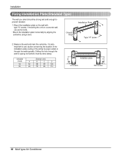
... must be strong and solid enough to power outlets is through the walls typically. Mount the installation plate on a concrete wall, use caution concerning the location of the installation plate-routing of the wiring to prevent vibration 1. It is also important to use anchor bolts.... • Mount the installation plate horizontally by aligning the centerline using a level. CHASSIS Distance (mm) (Grade) A B C D S4 50 105 59 105 SE 65 110 85 110 D Installation plate B C Ø70mm Left rear piping A Ø70mm Right ...
... must be strong and solid enough to power outlets is through the walls typically. Mount the installation plate on a concrete wall, use caution concerning the location of the installation plate-routing of the wiring to prevent vibration 1. It is also important to use anchor bolts.... • Mount the installation plate horizontally by aligning the centerline using a level. CHASSIS Distance (mm) (Grade) A B C D S4 50 105 59 105 SE 65 110 85 110 D Installation plate B C Ø70mm Left rear piping A Ø70mm Right ...
Service Manual
Page 19
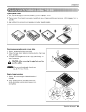
... connecting pipe path through the hole of cover side. Pipe hole Adhesive Only one desiring direction Connecting part Drain hose rubber cap Service Manual 19 Installation Preparing work for Installation (Artcool Type Only) Open panel front 1.
... connecting pipe path through the hole of cover side. Pipe hole Adhesive Only one desiring direction Connecting part Drain hose rubber cap Service Manual 19 Installation Preparing work for Installation (Artcool Type Only) Open panel front 1.
Service Manual
Page 20
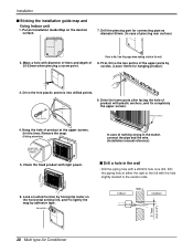
...left with a ø50mm hole core drill. INSTAIIATION GUIDE MAP 3. In case of nothing wrong in the matter, connect the pipe and the wire. (Installation manual reference) s Drill a hole in the wall. 8. Drive the lower parts after facing the hole of product with diameter of 6mm and depth of... with the hole slightly slanted to No. 5 on this time, Remove the map) (Falling attention) INSTALLATION GUIDE MAP Hanger hole (Rear side of the upper parts by adhesive tape. Put an Installation Guide Map on the horizontal setting line, and Fix lightly the map by screws. (Leave 10mm for...
...left with a ø50mm hole core drill. INSTAIIATION GUIDE MAP 3. In case of nothing wrong in the matter, connect the pipe and the wire. (Installation manual reference) s Drill a hole in the wall. 8. Drive the lower parts after facing the hole of product with diameter of 6mm and depth of... with the hole slightly slanted to No. 5 on this time, Remove the map) (Falling attention) INSTALLATION GUIDE MAP Hanger hole (Rear side of the upper parts by adhesive tape. Put an Installation Guide Map on the horizontal setting line, and Fix lightly the map by screws. (Leave 10mm for...
Service Manual
Page 22
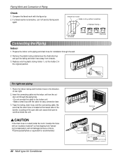
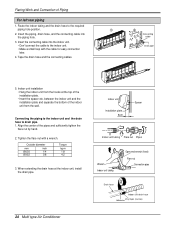
... dripping from chassis. 3. Compare the flared work again. Smooth all round Inside is defective, cut it off and do flaring work with the cable for installation through the piping hole. • Do not connect the cable to overflow inside the room, insulate the hose with an insulation material* so that the...
... dripping from chassis. 3. Compare the flared work again. Smooth all round Inside is defective, cut it off and do flaring work with the cable for installation through the piping hole. • Do not connect the cable to overflow inside the room, insulate the hose with an insulation material* so that the...

Service Manual
Page 23
Align the center of the pipes and sufficiently tighten the flare nut by moving it left and right sides of the unit against the installation plate until the hooks engage into the rear piping housing section. Wrap the insulation material around the connecting portion. 1. Bundle the piping and... drain hose together by wrapping them together with vinyl tape so that the hooks are properly seated on the installation plate by hand. 2. Press the lower left and right. Tighten the flare nut with vinyl tape. 3. Bind them with vinyl tape Drain hose...
Align the center of the pipes and sufficiently tighten the flare nut by moving it left and right sides of the unit against the installation plate until the hooks engage into the rear piping housing section. Wrap the insulation material around the connecting portion. 1. Bundle the piping and... drain hose together by wrapping them together with vinyl tape so that the hooks are properly seated on the installation plate by hand. 2. Press the lower left and right. Tighten the flare nut with vinyl tape. 3. Bind them with vinyl tape Drain hose...
Service Manual
Page 24
...Hang the indoor unit from the wall. Tighten the flare nut with the cable for easy connection later. 4. between the indoor unit and the installation plate and separate the bottom of the pipes and sufficiently tighten the flare nut by hand. 2. Align the center of the indoor unit from the... hooks at the indoor unit, install the drain pipe. 24 Multi type Air Conditioner Indoor unit Installation plate 8cm Spacer Indoor unit tubing Flare nut Pipes Wrench Indoor unit tubing Open-end wrench (fixed) Flare nut ...
...Hang the indoor unit from the wall. Tighten the flare nut with the cable for easy connection later. 4. between the indoor unit and the installation plate and separate the bottom of the pipes and sufficiently tighten the flare nut by hand. 2. Align the center of the indoor unit from the... hooks at the indoor unit, install the drain pipe. 24 Multi type Air Conditioner Indoor unit Installation plate 8cm Spacer Indoor unit tubing Flare nut Pipes Wrench Indoor unit tubing Open-end wrench (fixed) Flare nut ...
Service Manual
Page 25
...(narrow) Drain hose Pipe Vinyl tape(narrow) Wrap with vinyl tape so that the hooks are properly seated on the installation plate by wrapping them together with vinyl tape(wide) Indoor unit installation 1. Bundle the piping and drain hose together by moving it left and right sides of the unit against the... installation plate until the hooks engage into the rear piping housing section. Piping for passage through piping hole Connecting cable Drain hose Service Manual 25 Flaring ...
...(narrow) Drain hose Pipe Vinyl tape(narrow) Wrap with vinyl tape so that the hooks are properly seated on the installation plate by wrapping them together with vinyl tape(wide) Indoor unit installation 1. Bundle the piping and drain hose together by moving it left and right sides of the unit against the... installation plate until the hooks engage into the rear piping housing section. Piping for passage through piping hole Connecting cable Drain hose Service Manual 25 Flaring ...
Service Manual
Page 27
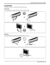
For left may cause damage to the tubing. Follow the instruction below. Service Manual 27 Flaring Work and Connection of clamp and unfold the tubing to downward slowly. Bad case • Following bending type from right to left piping. Good case • Press on the upper side of Piping Installation Information.
For left may cause damage to the tubing. Follow the instruction below. Service Manual 27 Flaring Work and Connection of clamp and unfold the tubing to downward slowly. Bad case • Following bending type from right to left piping. Good case • Press on the upper side of Piping Installation Information.
Service Manual
Page 30
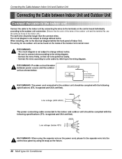
... diagram. Main power source Air Conditioner Circuit Breaker Use a circuit breaker or time delay fuse. RECOMMAND: The power cord connected to the Indoor unit. When installing, refer to the indoor and outdoor unit should be complied with the following specifications (ETL recognized and CSA certified). RECOMMAND: Provide a circuit breaker between Indoor...
... diagram. Main power source Air Conditioner Circuit Breaker Use a circuit breaker or time delay fuse. RECOMMAND: The power cord connected to the Indoor unit. When installing, refer to the indoor and outdoor unit should be complied with the following specifications (ETL recognized and CSA certified). RECOMMAND: Provide a circuit breaker between Indoor...
Service Manual
Page 35
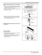
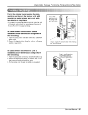
... of the drain outlet should be routed above the Indoor unit perform the following . 1. In cases where the outdoor unit is installed above the ground. Secure the taped piping along the exterior wall using saddle or equivalent. Trap Trap Service Manual 35 Tape the ...piping, drain hose and connecting cable from entering into electrical parts. In cases where the Outdoor unit is installed below the indoor unit perform the following . 1. Secure the drain hose appropriately. Taping Drain hose Plastic band Pipings Connecting cable Power supply...
... of the drain outlet should be routed above the Indoor unit perform the following . 1. In cases where the outdoor unit is installed above the ground. Secure the taped piping along the exterior wall using saddle or equivalent. Trap Trap Service Manual 35 Tape the ...piping, drain hose and connecting cable from entering into electrical parts. In cases where the Outdoor unit is installed below the indoor unit perform the following . 1. Secure the drain hose appropriately. Taping Drain hose Plastic band Pipings Connecting cable Power supply...


