Owner's Manual (English)
Page 2
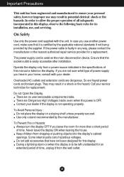
... your dealer if the display is faulty in potential eletrical shock or fire hazards. The power supply cord is to be left unattended for this manual or listed on a sloping shelf unless properly secured. A1 Contact your home, consult with the unit. In case you have not been designed for an...
... your dealer if the display is faulty in potential eletrical shock or fire hazards. The power supply cord is to be left unattended for this manual or listed on a sloping shelf unless properly secured. A1 Contact your home, consult with the unit. In case you have not been designed for an...
Owner's Manual (English)
Page 8
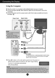
... want to adjust the monitor while in all countries.) PC MAC Mac adapter For Apple Macintosh use , or wish to model. However, be aware that is easily accessible and close to the display. 2 Power Cord Signal Cable Analog signal Digital signal D-sub DVI NOTE Varies according to manually run this option initializes...
... want to adjust the monitor while in all countries.) PC MAC Mac adapter For Apple Macintosh use , or wish to model. However, be aware that is easily accessible and close to the display. 2 Power Cord Signal Cable Analog signal Digital signal D-sub DVI NOTE Varies according to manually run this option initializes...
Owner's Manual (English)
Page 13
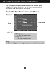
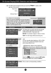
Menu Name PICTURE Icons Sub-menus Button Tip MENU : Exit : Adjust (Decrease/Increase) SET : Enter : Select another sub-menu NOTE OSD (On Screen Display) menu languages on the Menu. On Screen Display(OSD) Selection and Adjustment You were introduced to the procedure of the OSD appears. Press the MENU Button, then the main menu of selecting and adjusting an item using the OSD system. A12 Listed below are the icons, icon names, and icon descriptions of the all items shown on the monitor may differ from the manual.
Menu Name PICTURE Icons Sub-menus Button Tip MENU : Exit : Adjust (Decrease/Increase) SET : Enter : Select another sub-menu NOTE OSD (On Screen Display) menu languages on the Menu. On Screen Display(OSD) Selection and Adjustment You were introduced to the procedure of the OSD appears. Press the MENU Button, then the main menu of selecting and adjusting an item using the OSD system. A12 Listed below are the icons, icon names, and icon descriptions of the all items shown on the monitor may differ from the manual.
Owner's Manual (English)
Page 16
... conditions. The applied screen will appear on the left side, whereas the non-applied screen will appear on the screen as shown. You can manually adjust brightness, ACE or RCM. Screen when applied Screen when not applied Main menu Sub menu Description MOVIE This feature lets you touch the right... side of the monitor. Menu Name Icons Sub-menu Name button on the FLATRON F-ENGINE When you execute F-ENGINE, two tones will appear on the right side.Touch ...
... conditions. The applied screen will appear on the left side, whereas the non-applied screen will appear on the screen as shown. You can manually adjust brightness, ACE or RCM. Screen when applied Screen when not applied Main menu Sub menu Description MOVIE This feature lets you touch the right... side of the monitor. Menu Name Icons Sub-menu Name button on the FLATRON F-ENGINE When you execute F-ENGINE, two tones will appear on the right side.Touch ...
Owner's Manual (English)
Page 17
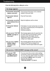
... turn on the screen? • This message appears when the signal cable between your PC and your display again. See the 'Specifications' section of this manual and configure your display is out of horizontal or vertical the screen? Do you see "OSD LOCKED" when you see a "CHECK SIGNAL CABLE" message on...
... turn on the screen? • This message appears when the signal cable between your PC and your display again. See the 'Specifications' section of this manual and configure your display is out of horizontal or vertical the screen? Do you see "OSD LOCKED" when you see a "CHECK SIGNAL CABLE" message on...

Service Manual
Page 1
Internal Use Only Website:http://biz.LGservice.com COLOR MONITOR SERVICE MANUAL CHASSIS NO. : LM57B MODEL: L1733TR (L1733TR-SFQ.A**MQP) L1933TR (L1933TR-SFQ.A**MQP,A**RQP) ( ) **Same model for Service CAUTION BEFORE SERVICING THE UNIT, READ THE SAFETY PRECAUTIONS IN THIS MANUAL. *To apply the MSTAR Chip.
Internal Use Only Website:http://biz.LGservice.com COLOR MONITOR SERVICE MANUAL CHASSIS NO. : LM57B MODEL: L1733TR (L1733TR-SFQ.A**MQP) L1933TR (L1933TR-SFQ.A**MQP,A**RQP) ( ) **Same model for Service CAUTION BEFORE SERVICING THE UNIT, READ THE SAFETY PRECAUTIONS IN THIS MANUAL. *To apply the MSTAR Chip.

Service Manual
Page 4
... removing the protective material from a carpeted floor can generate electrical charges sufficient to damage an ES device.) Copyright 2007 LG Electronics. Minimize bodily motions when handling unpackaged replacement ES devices. (Otherwise harmless motion such as "antistatic" can generate ...capacitors may result in not required. 6. Immediately before ; Use only a grounded-tip soldering iron to this service manual, lubrication of this service manual, clean electrical contacts only by applying the following servicing precautions and any heat sink in this publication. Inc. ...
... removing the protective material from a carpeted floor can generate electrical charges sufficient to damage an ES device.) Copyright 2007 LG Electronics. Minimize bodily motions when handling unpackaged replacement ES devices. (Otherwise harmless motion such as "antistatic" can generate ...capacitors may result in not required. 6. Immediately before ; Use only a grounded-tip soldering iron to this service manual, lubrication of this service manual, clean electrical contacts only by applying the following servicing precautions and any heat sink in this publication. Inc. ...

Service Manual
Page 16
...of Manufacture, Serial Number a) Input User Info Data b) Click "Update" button c) Click " Write" button e) Click Start button. ADJUSTMENT Windows EDID V1.0 User Manual Operating System: MS Windows 98, 2000, XP Port Setup: Windows 98 => Don't need setup Windows 2000, XP => Need to "c:\WINNT\system32\drivers" folder ...b) Run Userport.exe 2. Inc. f) Click Exit button. All right reserved. Only for training and service purposes - 16 - Copyright 2007 LG Electronics. Port Setup a) Copy "UserPort.sys" file to Port Setup. This program is available to LCD Monitor only. 1.
...of Manufacture, Serial Number a) Input User Info Data b) Click "Update" button c) Click " Write" button e) Click Start button. ADJUSTMENT Windows EDID V1.0 User Manual Operating System: MS Windows 98, 2000, XP Port Setup: Windows 98 => Don't need setup Windows 2000, XP => Need to "c:\WINNT\system32\drivers" folder ...b) Run Userport.exe 2. Inc. f) Click Exit button. All right reserved. Only for training and service purposes - 16 - Copyright 2007 LG Electronics. Port Setup a) Copy "UserPort.sys" file to Port Setup. This program is available to LCD Monitor only. 1.

Service Manual
Page 17
... Video Signal Generator Control Line IBM Compatible PC 15 10 5 PARALLEL PORT Not used RS232C PARALLEL OFF ON 5V C F VGS A MONITOR B V-SYNC ST POWER Power inlet (required) 220 Power Select Switch (110V/220V) Power LED E ST Switch F V-Sync On/...manually.(Analog Only) i) MODULE : To select applied module. LGE Internal Use Only b) NVRAM INIT : EEPROM initialize.(24C08) c) CLEAR ETI : To initialize using time. d) AGING : Select Aging mode(on/off the power switch at the front side of the display. 2) Wait for training and service purposes - 17 - Cable Connection Copyright 2007 LG...
... Video Signal Generator Control Line IBM Compatible PC 15 10 5 PARALLEL PORT Not used RS232C PARALLEL OFF ON 5V C F VGS A MONITOR B V-SYNC ST POWER Power inlet (required) 220 Power Select Switch (110V/220V) Power LED E ST Switch F V-Sync On/...manually.(Analog Only) i) MODULE : To select applied module. LGE Internal Use Only b) NVRAM INIT : EEPROM initialize.(24C08) c) CLEAR ETI : To initialize using time. d) AGING : Select Aging mode(on/off the power switch at the front side of the display. 2) Wait for training and service purposes - 17 - Cable Connection Copyright 2007 LG...
Service Manual
Page 27
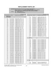
REPLACEMENT PARTS LIST CAUTION: BEFORE REPLACING ANY OF THESE COMPONENTS, READ CAREFULLY THE SAFETY PRECAUTIONS IN THIS MANUAL. MAIN BOARD AND POWER BOARD PARTS ARE DIFFERENT. * NOTE : S SAFETY Mark AL ALTERNATIVE PARTS *S *AL LOC. PART ...5.2TO6V BZT52C5V6S-(F) 5.6V 5.2TO6V BZT52C5V6S-(F) 5.6V 5.2TO6V BZT52C5V6S-(F) 5.6V 5.2TO6V FE251MOH-LF(TSUMO56WHJ-LF) 3 L1952HQ-SFQ ARDRQP TSUMO G Copyright 2007 LG Electronics. DESCRIPTION / SPECIFICATION 0603B104K160CT 100nF 10% 16V C1608X7R1E473KT 47nF 10% 25V C1608X7R1E473KT 47nF 10% 25V C1608X7R1E473KT 47nF 10% 25V C1608X7R1E473KT 47nF 10% 25V ...
REPLACEMENT PARTS LIST CAUTION: BEFORE REPLACING ANY OF THESE COMPONENTS, READ CAREFULLY THE SAFETY PRECAUTIONS IN THIS MANUAL. MAIN BOARD AND POWER BOARD PARTS ARE DIFFERENT. * NOTE : S SAFETY Mark AL ALTERNATIVE PARTS *S *AL LOC. PART ...5.2TO6V BZT52C5V6S-(F) 5.6V 5.2TO6V BZT52C5V6S-(F) 5.6V 5.2TO6V BZT52C5V6S-(F) 5.6V 5.2TO6V FE251MOH-LF(TSUMO56WHJ-LF) 3 L1952HQ-SFQ ARDRQP TSUMO G Copyright 2007 LG Electronics. DESCRIPTION / SPECIFICATION 0603B104K160CT 100nF 10% 16V C1608X7R1E473KT 47nF 10% 25V C1608X7R1E473KT 47nF 10% 25V C1608X7R1E473KT 47nF 10% 25V C1608X7R1E473KT 47nF 10% 25V ...


