Owner's Manual (English)
Page 2
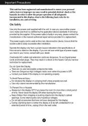
... the display on the display. A1 If the power cable is to be left unattended for its installation, use, and servicing. Overloaded AC outlets and extension cords are frayed power cords and broken plugs. Do not Open the Display. Keep children from the wall outlet. During a lightning storm or when the display is faulty in any way, please contact the manufacturer or the nearest authorized repair service provider...
... the display on the display. A1 If the power cable is to be left unattended for its installation, use, and servicing. Overloaded AC outlets and extension cords are frayed power cords and broken plugs. Do not Open the Display. Keep children from the wall outlet. During a lightning storm or when the display is faulty in any way, please contact the manufacturer or the nearest authorized repair service provider...
Owner's Manual (English)
Page 5
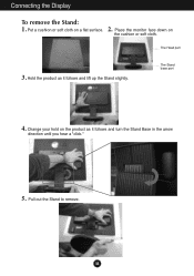
Change your hold on the product as it follows and turn the Stand Base in the arrow direction until you hear a "click." 5. Put a cushion or soft cloth on the cushion or soft cloth. The Head part 3. Pull out the Stand to remove. Connecting the Display To remove the Stand: 1. 2. The Stand base part 4. Hold the product as it follows and lift up the Stand slightly. A4 Place the monitor face down on a flat surface.
Change your hold on the product as it follows and turn the Stand Base in the arrow direction until you hear a "click." 5. Put a cushion or soft cloth on the cushion or soft cloth. The Head part 3. Pull out the Stand to remove. Connecting the Display To remove the Stand: 1. 2. The Stand base part 4. Hold the product as it follows and lift up the Stand slightly. A4 Place the monitor face down on a flat surface.

Owner's Manual (English)
Page 7
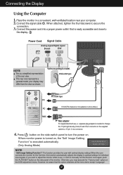
Connecting the Display Before setting up the monitor, ensure that in various ways for maximum comfort. Positioning your finger(s). You can hurt your display 1. A6 Tilt Range: -5˚~20˚ Swivel : 355˚(The feature is turned off. Ergonomic It is recommended that the power to the monitor,... adjusting the angle of the screen, do not put your finger in between the head of the panel in order to maintain an ergonomic and comfortable viewing position, the forward tilt angle of the monitor should not exceed 5 degrees. Adjust the position of the monitor and the stand ...
Connecting the Display Before setting up the monitor, ensure that in various ways for maximum comfort. Positioning your finger(s). You can hurt your display 1. A6 Tilt Range: -5˚~20˚ Swivel : 355˚(The feature is turned off. Ergonomic It is recommended that the power to the monitor,... adjusting the angle of the screen, do not put your finger in between the head of the panel in order to maintain an ergonomic and comfortable viewing position, the forward tilt angle of the monitor should not exceed 5 degrees. Adjust the position of the monitor and the stand ...
Owner's Manual (English)
Page 8
... thumbscrews to turn the power on the OSD adjustment menu. This function provides the user with optimal display settings.When the user connects the monitor for the first time, this function once again, push the 'AUTO/SET' button on the supplied cable to optimal settings for individual input signals. Otherwise, you want to adjust the monitor while in use , a separate plug adapter is needed to change the 15 pin high density (3 row) D-sub VGA connector on the side panel of the...
... thumbscrews to turn the power on the OSD adjustment menu. This function provides the user with optimal display settings.When the user connects the monitor for the first time, this function once again, push the 'AUTO/SET' button on the supplied cable to optimal settings for individual input signals. Otherwise, you want to adjust the monitor while in use , a separate plug adapter is needed to change the 15 pin high density (3 row) D-sub VGA connector on the side panel of the...
Owner's Manual (English)
Page 9
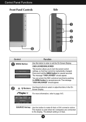
... be inadvertently changed. SOURCE Hot key Use this button to enter or exit the On Screen Display. OSD LOCKED/UNLOCKED This function allows you to page A15. This feature is D-Sub. Buttons Use these buttons to select or adjust functions in the On Screen Display. Press and hold the MENU button for several seconds. The message "OSD LOCKED" should appear. Control Panel Functions Front Panel Controls Side Control MENU Button Function Use this button to make D-Sub or DVI connector active.
... be inadvertently changed. SOURCE Hot key Use this button to enter or exit the On Screen Display. OSD LOCKED/UNLOCKED This function allows you to page A15. This feature is D-Sub. Buttons Use these buttons to select or adjust functions in the On Screen Display. Press and hold the MENU button for several seconds. The message "OSD LOCKED" should appear. Control Panel Functions Front Panel Controls Side Control MENU Button Function Use this button to make D-Sub or DVI connector active.

Owner's Manual (English)
Page 10
... best display mode is in Sleep Mode (Energy Saving), this indicator color changes to enter a selection in the On Screen Display. Power Indicator This Indicator lights up blue when the display operates normally(On Mode). This will automatically adjust your display settings, always press the AUTO/SET button before entering the On Screen Display(OSD). AUTO IMAGE ADJUSTMENT When adjusting your display image to turn the display on or off. Control Panel Functions Control AUTO/SET Button Function Use this button to amber. If the display is 17 inch monitor : 1280 x 1024 19 inch...
... best display mode is in Sleep Mode (Energy Saving), this indicator color changes to enter a selection in the On Screen Display. Power Indicator This Indicator lights up blue when the display operates normally(On Mode). This will automatically adjust your display settings, always press the AUTO/SET button before entering the On Screen Display(OSD). AUTO IMAGE ADJUSTMENT When adjusting your display image to turn the display on or off. Control Panel Functions Control AUTO/SET Button Function Use this button to amber. If the display is 17 inch monitor : 1280 x 1024 19 inch...
Owner's Manual (English)
Page 12
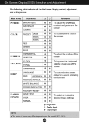
...adjustment, and setting menus. A11 Main menu Sub-menu A D Reference PICTURE BRIGHTNESS CONTRAST GAMMA To adjust the brightness, contrast and gamma of the screen COLOR POSITION PRESET sRGB 6500K 9300K RED GREEN BLUE HORIZONTAL VERTICAL To customize the color of the screen To adjust the position of the screen CLOCK TRACKING PHASE SHARPNESS To improve the clarity and stability, sharpness of the screen SETUP LANGUAGE OSD HORIZONTAL POSITION VERTICAL To customize the screen status for a user's operating environment FLATRON F-ENGINE WHITE BALANCE POWER INDICATOR FACTORY RESET...
...adjustment, and setting menus. A11 Main menu Sub-menu A D Reference PICTURE BRIGHTNESS CONTRAST GAMMA To adjust the brightness, contrast and gamma of the screen COLOR POSITION PRESET sRGB 6500K 9300K RED GREEN BLUE HORIZONTAL VERTICAL To customize the color of the screen To adjust the position of the screen CLOCK TRACKING PHASE SHARPNESS To improve the clarity and stability, sharpness of the screen SETUP LANGUAGE OSD HORIZONTAL POSITION VERTICAL To customize the screen status for a user's operating environment FLATRON F-ENGINE WHITE BALANCE POWER INDICATOR FACTORY RESET...

Owner's Manual (English)
Page 15
OSD To adjust position of the OSD window POSITION on the front side of the monitor to provide the optimal image. SETUP WHITE BALANCE If the output of the video card is an analog signal. FACTORY RESET Restore all factory default settings except "LANGUAGE." If necessary, perform the white balance function again. SET : Select another sub-menu Use this function, the signal level is adjusted to fit into the standard output level of the video card in the screen. If you...
OSD To adjust position of the OSD window POSITION on the front side of the monitor to provide the optimal image. SETUP WHITE BALANCE If the output of the video card is an analog signal. FACTORY RESET Restore all factory default settings except "LANGUAGE." If necessary, perform the white balance function again. SET : Select another sub-menu Use this function, the signal level is adjusted to fit into the standard output level of the video card in the screen. If you...
Owner's Manual (English)
Page 17
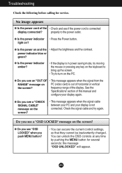
... display is out of horizontal or vertical the screen? A16 light on PC (video card) is not connected. G Do you see an "OUT OF • This message appears when the signal from the RANGE" message on ? frequency range of the • Check and see a "CHECK SIGNAL CABLE" message on the PC. Do you see a "OSD LOCKED" message on and the • Adjust the brightness and the contrast. No image appears G Is the power cord...
... display is out of horizontal or vertical the screen? A16 light on PC (video card) is not connected. G Do you see an "OUT OF • This message appears when the signal from the RANGE" message on ? frequency range of the • Check and see a "CHECK SIGNAL CABLE" message on the PC. Do you see a "OSD LOCKED" message on and the • Adjust the brightness and the contrast. No image appears G Is the power cord...
Owner's Manual (English)
Page 18
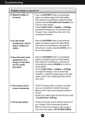
...; Press the AUTO/SET button to automatically adjust your display image to the ideal setting. Set the color setting higher than 24 bits (true color) at Control Panel - If the results are unsatisfactory, adjust the image position using the CLOCK icon in the on screen display. • Check Control Panel --> Display --> Settings and adjust the display to the recommended resolution or adjust the display image to be in the on screen display. • Check Control Panel --> Display --> Settings and see if the frequency or the resolution were changed. If the...
...; Press the AUTO/SET button to automatically adjust your display image to the ideal setting. Set the color setting higher than 24 bits (true color) at Control Panel - If the results are unsatisfactory, adjust the image position using the CLOCK icon in the on screen display. • Check Control Panel --> Display --> Settings and adjust the display to the recommended resolution or adjust the display image to be in the on screen display. • Check Control Panel --> Display --> Settings and see if the frequency or the resolution were changed. If the...
Owner's Manual (English)
Page 19
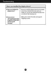
G Do you can also download the driver from the display driver CD (or diskette) that comes with your display. Or, you see an "Unrecognized monitor, Plug&Play (VESA DDC) monitor found" message? • Make sure to install the display driver from our web site: http://www.lge.com. G Have you installed the display driver? A18 Troubleshooting Have you installed the display driver? • Be sure to check if the video card supports Plug&Play function.
G Do you can also download the driver from the display driver CD (or diskette) that comes with your display. Or, you see an "Unrecognized monitor, Plug&Play (VESA DDC) monitor found" message? • Make sure to install the display driver from our web site: http://www.lge.com. G Have you installed the display driver? A18 Troubleshooting Have you installed the display driver? • Be sure to check if the video card supports Plug&Play function.
Owner's Manual (English)
Page 20
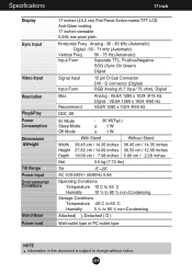
Specifications 17 inch Display Sync Input Video Input Resolution Plug&Play Power Consumption Dimensions &Weight Tilt Range Power Input Environmental Conditions Stand Base Power cord 17 inches (43.2 cm) Flat Panel Active matrix-TFT LCD Anti-Glare coating 17 inches viewable 0.264 mm pixel pitch Horizontal Freq. A19 D connector (Digital) RGB Analog (0.7 Vp-p/ 75 ohm), Digital Max Recommend Analog : VESA 1280 x 1024 @75 Hz Digital : VESA 1280 x 1024 @60 Hz VESA 1280 x 1024 @60 Hz DDC 2B 0n Mode Sleep Mode Off Mode : 30 W(Typ.) ≤ 1W ≤ 1W With Stand Without...
Specifications 17 inch Display Sync Input Video Input Resolution Plug&Play Power Consumption Dimensions &Weight Tilt Range Power Input Environmental Conditions Stand Base Power cord 17 inches (43.2 cm) Flat Panel Active matrix-TFT LCD Anti-Glare coating 17 inches viewable 0.264 mm pixel pitch Horizontal Freq. A19 D connector (Digital) RGB Analog (0.7 Vp-p/ 75 ohm), Digital Max Recommend Analog : VESA 1280 x 1024 @75 Hz Digital : VESA 1280 x 1024 @60 Hz VESA 1280 x 1024 @60 Hz DDC 2B 0n Mode Sleep Mode Off Mode : 30 W(Typ.) ≤ 1W ≤ 1W With Stand Without...

Owner's Manual (English)
Page 21
Specifications 19 inch Display Sync Input Video Input Resolution Plug&Play Power Consumption Dimensions &Weight Tilt Range Power Input Environmental Conditions Stand Base Power cord 19 inches (48.19 cm) Flat Panel Active matrix-TFT LCD Anti-Glare coating 19 inches viewable 0.294 mm pixel pitch Horizontal Freq. D connector (Digital) RGB Analog (0.7 Vp-p/ 75 ohm), Digital Max Recommend Analog : VESA 1280 x 1024 @75 Hz Digital : VESA 1280 x 1024 @60 Hz VESA 1280 x 1024 @60 Hz DDC 2B 0n Mode Sleep Mode Off Mode : 34 W(Typ.) ≤ 1W ≤ 1W Width Height Depth Net With Stand ...
Specifications 19 inch Display Sync Input Video Input Resolution Plug&Play Power Consumption Dimensions &Weight Tilt Range Power Input Environmental Conditions Stand Base Power cord 19 inches (48.19 cm) Flat Panel Active matrix-TFT LCD Anti-Glare coating 19 inches viewable 0.294 mm pixel pitch Horizontal Freq. D connector (Digital) RGB Analog (0.7 Vp-p/ 75 ohm), Digital Max Recommend Analog : VESA 1280 x 1024 @75 Hz Digital : VESA 1280 x 1024 @60 Hz VESA 1280 x 1024 @60 Hz DDC 2B 0n Mode Sleep Mode Off Mode : 34 W(Typ.) ≤ 1W ≤ 1W Width Height Depth Net With Stand ...
Service Manual
Page 2
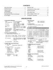
...lbs) L1933T Net. Resolution D-sub Analog Digital : 1280 x 1024@75Hz : 1280 x 1024@60Hz 5. Video Input Signal 1) Type 2) Voltage Level a) Color 0, 0 b) Color 7, 0 c) Color 15, 0 3) Input Impedance : R, G, B Analog : 0~0.71 V : 0 Vp-p : 0.467Vp-p : 0.714Vp-p : 75Ω 6. CONTENTS SPECIFICATIONS 2 PRECAUTIONS 3 TIMING CHART 7 DISASSEMBLY 8 BLOCK DIAGRAM 12 DISCRIPTION OF BLOCK DIAGRAM 14 ADJUSTMENT 16 SERVICE OSD 17 TROUBLESHOOTING GUIDE 18 WIRING DIAGRAM 24 EXPLODED VIEW 25 REPLACEMENT PARTS LIST 27 SCHEMATIC DIAGRAM 31 SPECIFICATIONS 1. L1733T : 0.294 (H) x 0.294...
...lbs) L1933T Net. Resolution D-sub Analog Digital : 1280 x 1024@75Hz : 1280 x 1024@60Hz 5. Video Input Signal 1) Type 2) Voltage Level a) Color 0, 0 b) Color 7, 0 c) Color 15, 0 3) Input Impedance : R, G, B Analog : 0~0.71 V : 0 Vp-p : 0.467Vp-p : 0.714Vp-p : 75Ω 6. CONTENTS SPECIFICATIONS 2 PRECAUTIONS 3 TIMING CHART 7 DISASSEMBLY 8 BLOCK DIAGRAM 12 DISCRIPTION OF BLOCK DIAGRAM 14 ADJUSTMENT 16 SERVICE OSD 17 TROUBLESHOOTING GUIDE 18 WIRING DIAGRAM 24 EXPLODED VIEW 25 REPLACEMENT PARTS LIST 27 SCHEMATIC DIAGRAM 31 SPECIFICATIONS 1. L1733T : 0.294 (H) x 0.294...

Service Manual
Page 4
... not remove a replacement ES device from the AC power source before connecting the test receiver positive lead. After removing an electrical assembly equipped with high voltage. 4. Only for training and service purposes -4- a. Always remove the test receiver ground lead last. 9. SERVICING PRECAUTIONS CAUTION: Before servicing receivers covered by conductive foam, aluminum foil or comparable conductive material). 7. Remember: Safety First. LGE Internal Use Only Always connect...
... not remove a replacement ES device from the AC power source before connecting the test receiver positive lead. After removing an electrical assembly equipped with high voltage. 4. Only for training and service purposes -4- a. Always remove the test receiver ground lead last. 9. SERVICING PRECAUTIONS CAUTION: Before servicing receivers covered by conductive foam, aluminum foil or comparable conductive material). 7. Remember: Safety First. LGE Internal Use Only Always connect...

Service Manual
Page 16
... LCD Monitor only. 1. LGE Internal Use Only EDID Read & Write 1) Run WinEDID.exe c) Remove all default number d) Add 300-3FF 2) Edit Week of Manufacture, Year of Manufacture, Serial Number a) Input User Info Data b) Click "Update" button c) Click " Write" button e) Click Start button. Inc. This program is available to "c:\WINNT\system32\drivers" folder b) Run Userport.exe 2. Copyright 2007 LG Electronics. ADJUSTMENT Windows EDID V1.0 User Manual Operating System: MS Windows 98, 2000, XP Port Setup: Windows...
... LCD Monitor only. 1. LGE Internal Use Only EDID Read & Write 1) Run WinEDID.exe c) Remove all default number d) Add 300-3FF 2) Edit Week of Manufacture, Year of Manufacture, Serial Number a) Input User Info Data b) Click "Update" button c) Click " Write" button e) Click Start button. Inc. This program is available to "c:\WINNT\system32\drivers" folder b) Run Userport.exe 2. Copyright 2007 LG Electronics. ADJUSTMENT Windows EDID V1.0 User Manual Operating System: MS Windows 98, 2000, XP Port Setup: Windows...

Service Manual
Page 17
... OSD menu contains additional menus that the User OSD menu as described below. d) AGING : Select Aging mode(on/off the power switch at the front side of the display. 2) Wait for training and service purposes - 17 - Video Signal Generator Control Line IBM Compatible PC 15 10 5 PARALLEL PORT Not used RS232C PARALLEL OFF ON 5V C F VGS A MONITOR B V-SYNC ST POWER Power inlet (required) 220 Power Select Switch (110V/220V) Power LED E ST Switch F V-Sync On/Off Switch (Switch...
... OSD menu contains additional menus that the User OSD menu as described below. d) AGING : Select Aging mode(on/off the power switch at the front side of the display. 2) Wait for training and service purposes - 17 - Video Signal Generator Control Line IBM Compatible PC 15 10 5 PARALLEL PORT Not used RS232C PARALLEL OFF ON 5V C F VGS A MONITOR B V-SYNC ST POWER Power inlet (required) 220 Power Select Switch (110V/220V) Power LED E ST Switch F V-Sync On/Off Switch (Switch...
Service Manual
Page 19
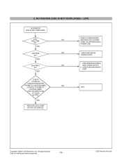
... NO RASTER (OSD IS NOT DISPLAYED) J403 NO PIN5, PIN6 5V? CHECK MICOM DIM-ADJ PORT LIPS Copyright 2007 LG Electronics. Inc. CAN YOU SEE PULSE AT YOUR SCOPE? YES J403 PIN10 NO 5V? YES REPLACE CCFL LAMP IN THE LCD MODULE CHECK POWER BOARD, AND FIND OUT A SHORT POINT AS OPENING EACH POWER LINE CHECK MICOM INV ON/OFF PORT. 1. LGE Internal Use Only
... NO RASTER (OSD IS NOT DISPLAYED) J403 NO PIN5, PIN6 5V? CHECK MICOM DIM-ADJ PORT LIPS Copyright 2007 LG Electronics. Inc. CAN YOU SEE PULSE AT YOUR SCOPE? YES J403 PIN10 NO 5V? YES REPLACE CCFL LAMP IN THE LCD MODULE CHECK POWER BOARD, AND FIND OUT A SHORT POINT AS OPENING EACH POWER LINE CHECK MICOM INV ON/OFF PORT. 1. LGE Internal Use Only
Service Manual
Page 20
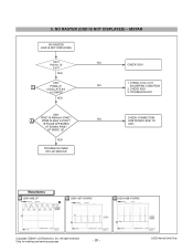
... 2. Inc. 3. YES CHECK U301 1. CHECK X201 3. AT MODE 12? All right reserved. MSTAR NO RASTER (OSD IS NOT DISPLAYED) U201 NO PIN 16, 75 3.3V? YES TROUBLE IN CABLE OR LCD MODULE CHECK CONNECTION LINE FROM D-SUB TO U201 Waveforms 1 U201-#96, 97 2 U201-#27 H-SYNC 2 U201-#28 V-SYNC Copyright 2007 LG Electronics. LGE Internal Use Only NO RASTER (OSD IS NOT DISPLAYED) - TROUBLE IN U201 U201...
... 2. Inc. 3. YES CHECK U301 1. CHECK X201 3. AT MODE 12? All right reserved. MSTAR NO RASTER (OSD IS NOT DISPLAYED) U201 NO PIN 16, 75 3.3V? YES TROUBLE IN CABLE OR LCD MODULE CHECK CONNECTION LINE FROM D-SUB TO U201 Waveforms 1 U201-#96, 97 2 U201-#27 H-SYNC 2 U201-#28 V-SYNC Copyright 2007 LG Electronics. LGE Internal Use Only NO RASTER (OSD IS NOT DISPLAYED) - TROUBLE IN U201 U201...

Service Manual
Page 26
... LG PHILIPS LCD or EAJ32188901 LCD,Module-TFT, LM190E08-TLB5 DRIVER 19INCH 1280X1024 300CD COLOR 72% 5/4 800 : 1 P4 FACTORY 5MS, 2CH-LVDS, 160/160, 4LAMP LG PHILIPS LCD . 6304FHS014B LCD,Module-TFT, HSD190ME13-D10(700VS1) DRIVER 19INCH 1280X1024 300CD COLOR 72% 4/3 700:1 - EXPLODED VIEW PARTS LIST * Note: Safety mark Ref. Only for L1733TR ABJ32229471 Cabinet Assembly, L1953 . 19" SILVER L1933TR FOR BEST BUY 020 EAJ32188801 LCD,Module-TFT, LM170E03-TLB3 DRIVER 17...
... LG PHILIPS LCD or EAJ32188901 LCD,Module-TFT, LM190E08-TLB5 DRIVER 19INCH 1280X1024 300CD COLOR 72% 5/4 800 : 1 P4 FACTORY 5MS, 2CH-LVDS, 160/160, 4LAMP LG PHILIPS LCD . 6304FHS014B LCD,Module-TFT, HSD190ME13-D10(700VS1) DRIVER 19INCH 1280X1024 300CD COLOR 72% 4/3 700:1 - EXPLODED VIEW PARTS LIST * Note: Safety mark Ref. Only for L1733TR ABJ32229471 Cabinet Assembly, L1953 . 19" SILVER L1933TR FOR BEST BUY 020 EAJ32188801 LCD,Module-TFT, LM170E03-TLB3 DRIVER 17...


