Owner's Manual (English)
Page 2
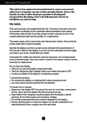
... a stand recommended by the applicable national standards as the main disconnection device. The power supply cord is used is OFF. They may result in this manual or listed on a sloping shelf unless properly secured. To Avoid Personal Injury : Do not place the display on the display.
... a stand recommended by the applicable national standards as the main disconnection device. The power supply cord is used is OFF. They may result in this manual or listed on a sloping shelf unless properly secured. To Avoid Personal Injury : Do not place the display on the display.
Owner's Manual (English)
Page 8
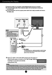
...proper power outlet that this option initializes all the menu items except 'Language'. When the user connects the monitor for individual input signals. Otherwise, you want to manually run this function automatically adjusts the display to model. your display may execute the ' Factory reset' ...Connecting the Display 1. When attached, tighten the thumbscrews to turn the power on the supplied cable to a 15 pin 2 row connector. 4. When monitor power is turned on the side switch panel to secure the connection. 1 3. Press button on , the 'Self Image Setting Function' is a simplified...
...proper power outlet that this option initializes all the menu items except 'Language'. When the user connects the monitor for individual input signals. Otherwise, you want to manually run this function automatically adjusts the display to model. your display may execute the ' Factory reset' ...Connecting the Display 1. When attached, tighten the thumbscrews to turn the power on the supplied cable to a 15 pin 2 row connector. 4. When monitor power is turned on the side switch panel to secure the connection. 1 3. Press button on , the 'Self Image Setting Function' is a simplified...
Owner's Manual (English)
Page 13
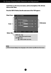
On Screen Display(OSD) Selection and Adjustment Listed below are the icons, icon names, and icon descriptions of the OSD appears. Menu Name PICTURE Icons Sub-menus Button Tip MENU : Exit : Adjust (Decrease/Increase) SET : Enter : Select another sub-menu NOTE OSD (On Screen Display) menu languages on the Menu. Press the MENU Button, then the main menu of the all items shown on the monitor may differ from the manual. A12
On Screen Display(OSD) Selection and Adjustment Listed below are the icons, icon names, and icon descriptions of the OSD appears. Menu Name PICTURE Icons Sub-menus Button Tip MENU : Exit : Adjust (Decrease/Increase) SET : Enter : Select another sub-menu NOTE OSD (On Screen Display) menu languages on the Menu. Press the MENU Button, then the main menu of the all items shown on the monitor may differ from the manual. A12
Owner's Manual (English)
Page 16
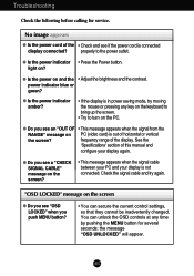
... calling for several seconds: the message "OSD UNLOCKED" will appear. light on and the • Adjust the brightness and the contrast. frequency range of this manual and configure your display is connected display connected? "OSD LOCKED" message on the screen G Do you see "OSD LOCKED" when you push MENU button? •...
... calling for several seconds: the message "OSD UNLOCKED" will appear. light on and the • Adjust the brightness and the contrast. frequency range of this manual and configure your display is connected display connected? "OSD LOCKED" message on the screen G Do you see "OSD LOCKED" when you push MENU button? •...
Service Manual
Page 1
Website:http://biz.LGservice.com E-mail:http://www.LGEservice.com/techsup.html COLOR MONITOR SERVICE MANUAL CHASSIS NO. : MODEL: L1718S (L1718S-SNQ/L1718S-BNQ.Axx*EP) xx* means sales region and Module (xxK : INNOLUX, xxB : CPT) CAUTION BEFORE SERVICING THE UNIT, READ THE SAFETY PRECAUTIONS IN THIS MANUAL. *To apply the MSTAR Chip.
Website:http://biz.LGservice.com E-mail:http://www.LGEservice.com/techsup.html COLOR MONITOR SERVICE MANUAL CHASSIS NO. : MODEL: L1718S (L1718S-SNQ/L1718S-BNQ.Axx*EP) xx* means sales region and Module (xxK : INNOLUX, xxB : CPT) CAUTION BEFORE SERVICING THE UNIT, READ THE SAFETY PRECAUTIONS IN THIS MANUAL. *To apply the MSTAR Chip.
Service Manual
Page 4
...CAUTION: A wrong part substitution or incorrect polarity installation of contacts in an explosion hazard. Unless specified otherwise in this service manual, lubrication of electrolytic capacitors may result in not required. 6. These can generate static electricity sufficient to any electrostatic charge on...precautions. 8. Immediately before handling any semiconductor component or semiconductor-equipped assembly, drain off any heat sink in this service manual. CAUTION: Be sure no power is a flammable mixture. Some solder removal devices not classified as the brushing together...
...CAUTION: A wrong part substitution or incorrect polarity installation of contacts in an explosion hazard. Unless specified otherwise in this service manual, lubrication of electrolytic capacitors may result in not required. 6. These can generate static electricity sufficient to any electrostatic charge on...precautions. 8. Immediately before handling any semiconductor component or semiconductor-equipped assembly, drain off any heat sink in this service manual. CAUTION: Be sure no power is a flammable mixture. Some solder removal devices not classified as the brushing together...
Service Manual
Page 13
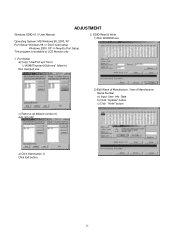
f) Click Exit button. 13 EDID Read & Write 1) Run WinEDID.exe 1. Port Setup a) Copy "UserPort.sys" file to LCD Monitor only. 2. This program is available to "c:\WINNT\system32\drivers" folder b) Run Userport.exe c) Remove all default number d) Add 300-3FF 2) Edit Week of Manufacture, Year of Manufacture, Serial Number a) Input User Info Data b) Click "Update" button c) Click " Write" button e) Click Start button. ADJUSTMENT Windows EDID V1.0 User Manual Operating System: MS Windows 98, 2000, XP Port Setup: Windows 98 => Don't need setup Windows 2000, XP => Need to Port Setup.
f) Click Exit button. 13 EDID Read & Write 1) Run WinEDID.exe 1. Port Setup a) Copy "UserPort.sys" file to LCD Monitor only. 2. This program is available to "c:\WINNT\system32\drivers" folder b) Run Userport.exe c) Remove all default number d) Add 300-3FF 2) Edit Week of Manufacture, Year of Manufacture, Serial Number a) Input User Info Data b) Click "Update" button c) Click " Write" button e) Click Start button. ADJUSTMENT Windows EDID V1.0 User Manual Operating System: MS Windows 98, 2000, XP Port Setup: Windows 98 => Don't need setup Windows 2000, XP => Need to Port Setup.
Service Manual
Page 14
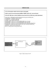
b) NVRAM INIT : EEPROM initialize.(24C04) c) CLEAR ETI : To initialize using time. g) R/G/B-Offset : Allows you to set the R/G/B-Offset value manually.(Analog Only) h) R/G/B-Gain : Allows you to set the R/G/B-9300K value manually. SERVICE OSD 1) Turn off ). a) Auto Color : W/B balance and Automatically sets the gain and offset value. f) R/G/B-6500K : Allows you to set the ...OSD menu contains additional menus that the User OSD menu as described below. d) AGING : Select Aging mode(on PC ISP Board D-SUB 15PIN Parallel Port LCD Monitor DSub Figure 1.Cable Connection For ISP 14
b) NVRAM INIT : EEPROM initialize.(24C04) c) CLEAR ETI : To initialize using time. g) R/G/B-Offset : Allows you to set the R/G/B-Offset value manually.(Analog Only) h) R/G/B-Gain : Allows you to set the R/G/B-9300K value manually. SERVICE OSD 1) Turn off ). a) Auto Color : W/B balance and Automatically sets the gain and offset value. f) R/G/B-6500K : Allows you to set the ...OSD menu contains additional menus that the User OSD menu as described below. d) AGING : Select Aging mode(on PC ISP Board D-SUB 15PIN Parallel Port LCD Monitor DSub Figure 1.Cable Connection For ISP 14


