Owner's Manual (English)
Page 2
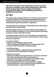
... in the specifications of time. Do not Open the Display. Never leave the display ON when leaving the house. If the power cable is faulty in this display. The power supply cord is used is OFF. Operate the display only from a power source indicated in potential eletrical shock or fire hazards. Contact your service technician for replacement. To Prevent Fire or Hazards: Always turn the display OFF if...
... in the specifications of time. Do not Open the Display. Never leave the display ON when leaving the house. If the power cable is faulty in this display. The power supply cord is used is OFF. Operate the display only from a power source indicated in potential eletrical shock or fire hazards. Contact your service technician for replacement. To Prevent Fire or Hazards: Always turn the display OFF if...
Owner's Manual (English)
Page 3
... its original material. Cover the openings with anything to rest upon or roll over the power cord, and do not place the display where the power cord is characteristic of the fixed-resolution LCD panel. If possible, use the recommended resolution to allow anything hard as this may result in accordance to damage. If used in the cabinet to obtain the best image quality for a long...
... its original material. Cover the openings with anything to rest upon or roll over the power cord, and do not place the display where the power cord is characteristic of the fixed-resolution LCD panel. If possible, use the recommended resolution to allow anything hard as this may result in accordance to damage. If used in the cabinet to obtain the best image quality for a long...
Owner's Manual (English)
Page 4
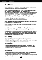
... REAR FRONT Make sure you push it until you hear it could damage the stand. Do not carry the product upside down holding only the stand base. REAR REAR Connecting the Display Before setting up carefully and face the front side Important Do not remove and re-install the stand frequently, it "click". 3. Assemble the Stand Body into the Stand Body in the picture.
... REAR FRONT Make sure you push it until you hear it could damage the stand. Do not carry the product upside down holding only the stand base. REAR REAR Connecting the Display Before setting up carefully and face the front side Important Do not remove and re-install the stand frequently, it "click". 3. Assemble the Stand Body into the Stand Body in the picture.
Owner's Manual (English)
Page 5
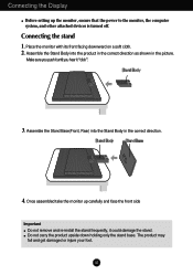
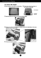
Put a cushion or soft cloth on the cushion or soft cloth. A4 Change your hold on the product as it follows and turn the Stand Base in the arrow direction until you hear a "click." 5. Place the monitor face down on a flat surface. The Stand base part 4. Pull out the Stand to remove. Hold the product as it follows and lift up the Stand slightly. The Head part 3. Connecting the Display To remove the Stand: 1. 2.
Put a cushion or soft cloth on the cushion or soft cloth. A4 Change your hold on the product as it follows and turn the Stand Base in the arrow direction until you hear a "click." 5. Place the monitor face down on a flat surface. The Stand base part 4. Pull out the Stand to remove. Hold the product as it follows and lift up the Stand slightly. The Head part 3. Connecting the Display To remove the Stand: 1. 2.
Owner's Manual (English)
Page 7
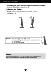
... Connecting the Display Before setting up the monitor, ensure that in order to the monitor, the computer system, and other attached devices is recommended that the power to maintain an ergonomic and comfortable viewing position, the forward tilt angle of the monitor should not exceed 5 degrees. Adjust the position of the panel in between the head of the screen, do not put your finger(s). Tilt Range...
... Connecting the Display Before setting up the monitor, ensure that in order to the monitor, the computer system, and other attached devices is recommended that the power to maintain an ergonomic and comfortable viewing position, the forward tilt angle of the monitor should not exceed 5 degrees. Adjust the position of the panel in between the head of the screen, do not put your finger(s). Tilt Range...
Owner's Manual (English)
Page 8
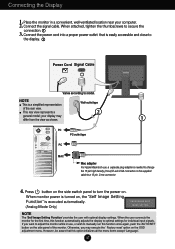
...OSD adjustment menu. This rear view represents a 2 general model; NOTE This is executed automatically. (Analog Mode Only) NOTE The 'Self Image Setting Function' provides the user with optimal display settings. Press button on the side switch panel to model. When the user connects the monitor for individual input signals. Connecting the Display 1. Place the monitor in use , a separate plug adapter is easily accessible and close to the display. 2 Power Cord Signal Cable Varies according to turn the power on , the 'Self Image Setting Function' is a simplified representation Wall...
...OSD adjustment menu. This rear view represents a 2 general model; NOTE This is executed automatically. (Analog Mode Only) NOTE The 'Self Image Setting Function' provides the user with optimal display settings. Press button on the side switch panel to model. When the user connects the monitor for individual input signals. Connecting the Display 1. Place the monitor in use , a separate plug adapter is easily accessible and close to the display. 2 Power Cord Signal Cable Varies according to turn the power on , the 'Self Image Setting Function' is a simplified representation Wall...
Owner's Manual (English)
Page 9
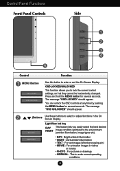
... Panel Controls Side Control Function MENU Button Use this button to select or adjust functions in videos or movies • PHOTO : For pictures or drawings • NORMAL : This is under normal operating conditions A8 Buttons Use these buttons to enter or exit the On Screen Display. OSD LOCKED/UNLOCKED This function allows you easily select the best desired NIGHT image condition optimized to lock the current control settings, so that they cannot be inadvertently changed...
... Panel Controls Side Control Function MENU Button Use this button to select or adjust functions in videos or movies • PHOTO : For pictures or drawings • NORMAL : This is under normal operating conditions A8 Buttons Use these buttons to enter or exit the On Screen Display. OSD LOCKED/UNLOCKED This function allows you easily select the best desired NIGHT image condition optimized to lock the current control settings, so that they cannot be inadvertently changed...
Owner's Manual (English)
Page 10
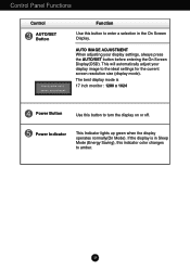
... is 17 inch monitor : 1280 x 1024 Power Button Use this button to enter a selection in Sleep Mode (Energy Saving), this indicator color changes to the ideal settings for the current screen resolution size (display mode). Power Indicator This Indicator lights up green when the display operates normally(On Mode). This will automatically adjust your display settings, always press the AUTO/SET button before entering the On Screen Display(OSD). A9 AUTO IMAGE ADJUSTMENT When adjusting your display image to amber. The best display mode is in the On Screen Display. Control Panel...
... is 17 inch monitor : 1280 x 1024 Power Button Use this button to enter a selection in Sleep Mode (Energy Saving), this indicator color changes to the ideal settings for the current screen resolution size (display mode). Power Indicator This Indicator lights up green when the display operates normally(On Mode). This will automatically adjust your display settings, always press the AUTO/SET button before entering the On Screen Display(OSD). A9 AUTO IMAGE ADJUSTMENT When adjusting your display image to amber. The best display mode is in the On Screen Display. Control Panel...
Owner's Manual (English)
Page 12
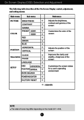
...and setting menus. Main menu Sub menu PICTURE COLOR POSITION BRIGHTNESS CONTRAST GAMMA PRESET 6500K 9300K RED GREEN BLUE HORIZONTAL VERTICAL CLOCK TRACKING PHASE LANGUAGE SETUP OSD HORIZONTAL POSITION VERTICAL WHITE BALANCE POWER INDICATOR FACTORY RESET Reference Adjusts the brightness, contrast and gamma of the screen Customizes the color of the screen Adjusts the position of the screen Improves the clarity and stability, sharpness of the screen Customizes the screen status for a user's operating environment : Adjustable NOTE The order of icons may differ depending on the model...
...and setting menus. Main menu Sub menu PICTURE COLOR POSITION BRIGHTNESS CONTRAST GAMMA PRESET 6500K 9300K RED GREEN BLUE HORIZONTAL VERTICAL CLOCK TRACKING PHASE LANGUAGE SETUP OSD HORIZONTAL POSITION VERTICAL WHITE BALANCE POWER INDICATOR FACTORY RESET Reference Adjusts the brightness, contrast and gamma of the screen Customizes the color of the screen Adjusts the position of the screen Improves the clarity and stability, sharpness of the screen Customizes the screen status for a user's operating environment : Adjustable NOTE The order of icons may differ depending on the model...
Owner's Manual (English)
Page 14
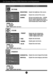
Adjusts red color levels. POSITION POSITION HORIZONTAL Adjusts the screen image left and right. COLOR COLOR PRESET RED GREEN BLUE MENU : Exit : Decrease : Increase SET : Select another sub-menu A13 Adjusts blue color levels. VERTICAL Adjusts the screen image up and down. Adjusts green color levels. CONTRAST Adjusts the contrast of the screen. On Screen Display(OSD) Selection and Adjustment Main menu Sub menu Description PICTURE PICTURE BRIGHTNESS Adjusts the brightness of the screen. MENU : Exit : Decrease : Increase SET : Select another sub-menu Selects the color...
Adjusts red color levels. POSITION POSITION HORIZONTAL Adjusts the screen image left and right. COLOR COLOR PRESET RED GREEN BLUE MENU : Exit : Decrease : Increase SET : Select another sub-menu A13 Adjusts blue color levels. VERTICAL Adjusts the screen image up and down. Adjusts green color levels. CONTRAST Adjusts the contrast of the screen. On Screen Display(OSD) Selection and Adjustment Main menu Sub menu Description PICTURE PICTURE BRIGHTNESS Adjusts the brightness of the screen. MENU : Exit : Decrease : Increase SET : Select another sub-menu Selects the color...
Owner's Manual (English)
Page 15
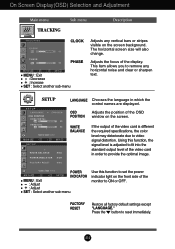
... optimal image. The horizontal screen size will also change. WHITE BALANCE If the output of the video card is adjusted to fit into the standard output level of the monitor to ON or OFF. POWER MENU - + SET INDICATOR MENU : Exit : Adjust : Adjust SET : Select another sub-menu Adjusts any horizontal noise and clear or sharpen text. SETUP + SET LANGUAGE Chooses the language in order to video signal distortion. FACTORY RESET Restore all factory default settings except "LANGUAGE." OSD Adjusts the position of the display. Press the button to remove...
... optimal image. The horizontal screen size will also change. WHITE BALANCE If the output of the video card is adjusted to fit into the standard output level of the monitor to ON or OFF. POWER MENU - + SET INDICATOR MENU : Exit : Adjust : Adjust SET : Select another sub-menu Adjusts any horizontal noise and clear or sharpen text. SETUP + SET LANGUAGE Chooses the language in order to video signal distortion. FACTORY RESET Restore all factory default settings except "LANGUAGE." OSD Adjusts the position of the display. Press the button to remove...
Owner's Manual (English)
Page 16
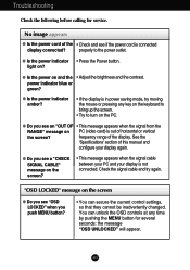
... power cord of horizontal or vertical the screen? G Is the power indicator amber? • If the display is out of the • Check and see a "CHECK SIGNAL CABLE" message on the PC. "OSD LOCKED" message on PC (video card) is in power saving mode, try again. Troubleshooting Check the following before calling for several seconds: the message "OSD UNLOCKED" will appear. G Is the power indicator • Press the Power button. See the 'Specifications' section of the display. Check...
... power cord of horizontal or vertical the screen? G Is the power indicator amber? • If the display is out of the • Check and see a "CHECK SIGNAL CABLE" message on the PC. "OSD LOCKED" message on PC (video card) is in power saving mode, try again. Troubleshooting Check the following before calling for several seconds: the message "OSD UNLOCKED" will appear. G Is the power indicator • Press the Power button. See the 'Specifications' section of the display. Check...
Owner's Manual (English)
Page 17
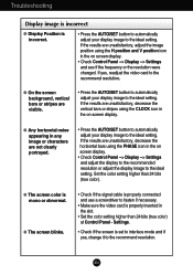
..., adjust the image position using the PHASE icon in the on screen display. G The screen color is set to interlace mode and if yes, change it to the ideal setting. If the results are unsatisfactory, decrease the horizontal bars using the H position and V position icon in the on screen display. • Check Control Panel --> Display --> Settings and see if the frequency or the resolution were changed. A16 Settings. • Check if the screen is mono or abnormal. Troubleshooting Display image is incorrect G Display Position...
..., adjust the image position using the PHASE icon in the on screen display. G The screen color is set to interlace mode and if yes, change it to the ideal setting. If the results are unsatisfactory, decrease the horizontal bars using the H position and V position icon in the on screen display. • Check Control Panel --> Display --> Settings and see if the frequency or the resolution were changed. A16 Settings. • Check if the screen is mono or abnormal. Troubleshooting Display image is incorrect G Display Position...
Owner's Manual (English)
Page 18
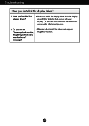
A17 G Have you can also download the driver from the display driver CD (or diskette) that comes with your display. Or, you installed the display driver? • Be sure to check if the video card supports Plug&Play function. Troubleshooting Have you see an "Unrecognized monitor, Plug&Play (VESA DDC) monitor found" message? • Make sure to install the display driver from our web site: http://www.lge.com. G Do you installed the display driver?
A17 G Have you can also download the driver from the display driver CD (or diskette) that comes with your display. Or, you installed the display driver? • Be sure to check if the video card supports Plug&Play function. Troubleshooting Have you see an "Unrecognized monitor, Plug&Play (VESA DDC) monitor found" message? • Make sure to install the display driver from our web site: http://www.lge.com. G Do you installed the display driver?
Owner's Manual (English)
Page 19
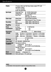
Specifications Display Sync Input Video Input Resolution Plug&Play Power Consumption Dimensions &Weight Tilt Range Power Input Environmental Conditions Stand Power cord 17 inches (43.2 cm) Flat Panel Active matrix-TFT LCD Anti-Glare coating 17 inches viewable 0.264 mm pixel pitch Horizontal Freq. 30 - 83 kHz (Automatic) Vertical Freq. 50 - 75 Hz (Automatic) Input Form Separate TTL SOG (Sync On Green) Signal Input 15 pin D-Sub Connector Input Form RGB Analog (0.7 Vp-p/ 75 ohm) Max Recommend VESA 1280 x 1024 @75 Hz VESA 1280 x 1024 @60 Hz DDC 2B...
Specifications Display Sync Input Video Input Resolution Plug&Play Power Consumption Dimensions &Weight Tilt Range Power Input Environmental Conditions Stand Power cord 17 inches (43.2 cm) Flat Panel Active matrix-TFT LCD Anti-Glare coating 17 inches viewable 0.264 mm pixel pitch Horizontal Freq. 30 - 83 kHz (Automatic) Vertical Freq. 50 - 75 Hz (Automatic) Input Form Separate TTL SOG (Sync On Green) Signal Input 15 pin D-Sub Connector Input Form RGB Analog (0.7 Vp-p/ 75 ohm) Max Recommend VESA 1280 x 1024 @75 Hz VESA 1280 x 1024 @60 Hz DDC 2B...
Owner's Manual (English)
Page 22
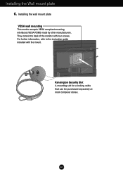
They connect to the instruction guide included with four screws. A21 For further information, refer to back of the monitor with the mount. Kensington Security Slot A mounting slot for a locking cable that can be purchased separately at most computer stores. Installing the Wall mount plate 6. Installing the wall mount plate VESA wall mounting This monitor accepts VESA compliant mounting interfaces (VESA FDMI) made by other manufacturers.
They connect to the instruction guide included with four screws. A21 For further information, refer to back of the monitor with the mount. Kensington Security Slot A mounting slot for a locking cable that can be purchased separately at most computer stores. Installing the Wall mount plate 6. Installing the wall mount plate VESA wall mounting This monitor accepts VESA compliant mounting interfaces (VESA FDMI) made by other manufacturers.
Service Manual
Page 2
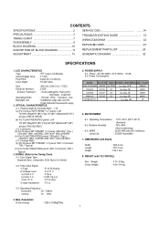
...176;)/Bottom67°(85°) at type CR≥10(CR≥5) 2-2. OPTICAL CHARACTERISTICS 2-1. Operating Frequency Horizontal : 30 ~ 83kHz Vertical : 56 ~ 75Hz 4. Power : AC 90~264V, 47.5~63Hz , POWER SUPPLY 5-1. Sync Signal Type : Separate Sync, Composite, SOG (Sync On Green) 3-2. CONTENTS SPECIFICATIONS 2 PRECAUTIONS 3 TIMING CHART 7 DISASSEMBLY 8 BLOCK DIAGRAM 10 DISCRIPTION OF BLOCK DIAGRAM 11 ADJUSTMENT 13 SERVICE OSD 14 TROUBLESHOOTING GUIDE 15 WIRING DIAGRAM 22 EXPLODED VIEW 23 REPLACEMENT PARTS LIST 24 SCHEMATIC DIAGRAM 32 SPECIFICATIONS 1.
...176;)/Bottom67°(85°) at type CR≥10(CR≥5) 2-2. OPTICAL CHARACTERISTICS 2-1. Operating Frequency Horizontal : 30 ~ 83kHz Vertical : 56 ~ 75Hz 4. Power : AC 90~264V, 47.5~63Hz , POWER SUPPLY 5-1. Sync Signal Type : Separate Sync, Composite, SOG (Sync On Green) 3-2. CONTENTS SPECIFICATIONS 2 PRECAUTIONS 3 TIMING CHART 7 DISASSEMBLY 8 BLOCK DIAGRAM 10 DISCRIPTION OF BLOCK DIAGRAM 11 ADJUSTMENT 13 SERVICE OSD 14 TROUBLESHOOTING GUIDE 15 WIRING DIAGRAM 22 EXPLODED VIEW 23 REPLACEMENT PARTS LIST 24 SCHEMATIC DIAGRAM 32 SPECIFICATIONS 1.
Service Manual
Page 4
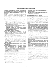
... component or semiconductor-equipped assembly, drain off any other electrical connection. b. CAUTION: A wrong part substitution or incorrect polarity installation of contacts in this receiver. d. Test high voltage only by measuring it . (Most replacement ES devices are packaged with which receivers covered by this service manual might be removed to prevent potential shock reasons prior to applying power to the chassis...
... component or semiconductor-equipped assembly, drain off any other electrical connection. b. CAUTION: A wrong part substitution or incorrect polarity installation of contacts in this receiver. d. Test high voltage only by measuring it . (Most replacement ES devices are packaged with which receivers covered by this service manual might be removed to prevent potential shock reasons prior to applying power to the chassis...
Service Manual
Page 13
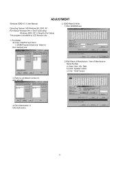
This program is available to "c:\WINNT\system32\drivers" folder b) Run Userport.exe c) Remove all default number d) Add 300-3FF 2) Edit Week of Manufacture, Year of Manufacture, Serial Number a) Input User Info Data b) Click "Update" button c) Click " Write" button e) Click Start button. f) Click Exit button. 13 Port Setup a) Copy "UserPort.sys" file to LCD Monitor only. 2. ADJUSTMENT Windows EDID V1.0 User Manual Operating System: MS Windows 98, 2000, XP Port Setup: Windows 98 => Don't need setup Windows 2000, XP => Need to Port Setup. EDID Read & Write 1) Run WinEDID.exe 1.
This program is available to "c:\WINNT\system32\drivers" folder b) Run Userport.exe c) Remove all default number d) Add 300-3FF 2) Edit Week of Manufacture, Year of Manufacture, Serial Number a) Input User Info Data b) Click "Update" button c) Click " Write" button e) Click Start button. f) Click Exit button. 13 Port Setup a) Copy "UserPort.sys" file to LCD Monitor only. 2. ADJUSTMENT Windows EDID V1.0 User Manual Operating System: MS Windows 98, 2000, XP Port Setup: Windows 98 => Don't need setup Windows 2000, XP => Need to Port Setup. EDID Read & Write 1) Run WinEDID.exe 1.
Service Manual
Page 14
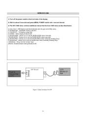
... value manually.(Analog Only) h) R/G/B-Gain : Allows you to Parallel Port on /off the power switch at the front side of the display. 2) Wait for about 5 seconds and press MENU, POWER switch with 1 second interval. 3) The SVC OSD menu contains additional menus that the User OSD menu as described below. d) AGING : Select Aging mode(on PC ISP Board D-SUB 15PIN Parallel Port LCD Monitor DSub Figure 1.Cable Connection For ISP 14 a) Auto Color : W/B balance...
... value manually.(Analog Only) h) R/G/B-Gain : Allows you to Parallel Port on /off the power switch at the front side of the display. 2) Wait for about 5 seconds and press MENU, POWER switch with 1 second interval. 3) The SVC OSD menu contains additional menus that the User OSD menu as described below. d) AGING : Select Aging mode(on PC ISP Board D-SUB 15PIN Parallel Port LCD Monitor DSub Figure 1.Cable Connection For ISP 14 a) Auto Color : W/B balance...


