

Owner's Manual
Page 1
LED LCD MONITOR MODELS E1960S E1960T E2060S E2060T E2260S E2260T E2260V E2360S E2360T E2360V www.lg.com ENGLISH OWNER'S MANUAL LED LCD MONITOR Please read this manual carefully before operating your set and retain it for future reference.
LED LCD MONITOR MODELS E1960S E1960T E2060S E2060T E2260S E2260T E2260V E2360S E2360T E2360V www.lg.com ENGLISH OWNER'S MANUAL LED LCD MONITOR Please read this manual carefully before operating your set and retain it for future reference.
Owner's Manual
Page 2
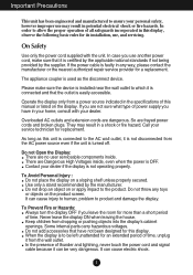
If you are not sure what type of power supply you have not been designed for this unit is installed near the wall outlet to product and damage the display. To Avoid Personal Injury : Do not place the display on the product screen. Keep children from the wall outlet. Some internal parts carry hazardous voltages. Do not add accessories that have in your home, consult with the unit. If the power cable is used as this display. The appliance coupler is faulty in any toys or objects on a sloping shelf unless properly secured. Overloaded AC outlets and extension cords are...
If you are not sure what type of power supply you have not been designed for this unit is installed near the wall outlet to product and damage the display. To Avoid Personal Injury : Do not place the display on the product screen. Keep children from the wall outlet. Some internal parts carry hazardous voltages. Do not add accessories that have in your home, consult with the unit. If the power cable is used as this display. The appliance coupler is faulty in any toys or objects on a sloping shelf unless properly secured. Overloaded AC outlets and extension cords are...
Owner's Manual
Page 3
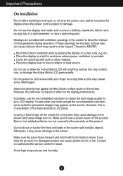
Place the display near a swimming pool. Some dot defects may appear as this may scratch, mar, or damage the Active Matrix LCD permanently. However, this may cause some scaled or processed images may cause damage to damage. Do not shock or scratch the front and sides of the screen with both hands to move. Make sure the panel faces forward and hold it may appear on the screen. If these openings are blocked, built-up heat can cause electric shock or fire. Cover the openings with anything to obtain the best image quality for your finger for a long time as near a bathtub, ...
Place the display near a swimming pool. Some dot defects may appear as this may scratch, mar, or damage the Active Matrix LCD permanently. However, this may cause some scaled or processed images may cause damage to damage. Do not shock or scratch the front and sides of the screen with both hands to move. Make sure the panel faces forward and hold it may appear on the screen. If these openings are blocked, built-up heat can cause electric shock or fire. Cover the openings with anything to obtain the best image quality for your finger for a long time as near a bathtub, ...
Owner's Manual
Page 4
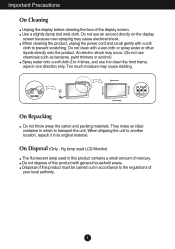
An electric shock may occur. (Do not use chemicals such as benzene, paint thinners or alcohol) Spray water onto a soft cloth 2 to 4 times, and use an aerosol directly on the display screen because over-spraying may cause staining. Do not clean with general household waste. wipe in its original material. On Repacking Do not throw away the carton and packing materials. On Disposal (Only , Hg lamp used LCD Monitor) The fluorescent lamp used in this product with a wet cloth or spray water or other liquids directly onto the product. Disposal of mercury. Use a slightly damp ...
An electric shock may occur. (Do not use chemicals such as benzene, paint thinners or alcohol) Spray water onto a soft cloth 2 to 4 times, and use an aerosol directly on the display screen because over-spraying may cause staining. Do not clean with general household waste. wipe in its original material. On Repacking Do not throw away the carton and packing materials. On Disposal (Only , Hg lamp used LCD Monitor) The fluorescent lamp used in this product with a wet cloth or spray water or other liquids directly onto the product. Disposal of mercury. Use a slightly damp ...
Owner's Manual
Page 5
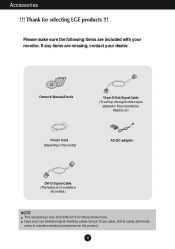
Owner's Manual/Cards 15-pin D-Sub Signal Cable (To set it up, this signal cable may be attached to maintain standard compliance for selecting LGE products !!! If any items are included with ferrite cores to this product before shipping out.) Power Cord (Depending on the country) AC-DC adapter DVI-D Signal Cable (This feature is not available in all countries.) NOTE This accessories may look different from those shown here. Please make sure the following items are missing, contact your monitor. Thank for the product. 4 Accessories !!! User must use shielded signal interface...
Owner's Manual/Cards 15-pin D-Sub Signal Cable (To set it up, this signal cable may be attached to maintain standard compliance for selecting LGE products !!! If any items are included with ferrite cores to this product before shipping out.) Power Cord (Depending on the country) AC-DC adapter DVI-D Signal Cable (This feature is not available in all countries.) NOTE This accessories may look different from those shown here. Please make sure the following items are missing, contact your monitor. Thank for the product. 4 Accessories !!! User must use shielded signal interface...

Owner's Manual
Page 6
Place the monitor face down on the cushion or soft cloth. 2. Stand Body Stand Base 3. Once assembled take the monitor up the monitor, ensure that the power to the monitor, the computer system, and other attached devices is turned off. Connecting the Display Before setting up carefully and face the front side. 5 Screw : Turn the screw by turning the screw to the Stand Base by using the screw handle. 4. Assemble the Stand Base into the Stand Body in the correct direction as shown in the picture. Attach the monitor to the right. Connecting the stand 1.
Place the monitor face down on the cushion or soft cloth. 2. Stand Body Stand Base 3. Once assembled take the monitor up the monitor, ensure that the power to the monitor, the computer system, and other attached devices is turned off. Connecting the Display Before setting up carefully and face the front side. 5 Screw : Turn the screw by turning the screw to the Stand Base by using the screw handle. 4. Assemble the Stand Base into the Stand Body in the correct direction as shown in the picture. Attach the monitor to the right. Connecting the stand 1.
Owner's Manual
Page 7
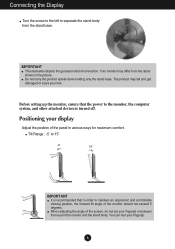
The product may differ from the stand base. Connecting the Display Turn the screw to the left to separate the stand body from the items shown in the picture. Tilt Range : -5˚ to maintain an ergonomic and comfortable viewing position, the forward tilt angle of the monitor and the stand body. Positioning your foot. Your monitor may fall and get damaged or injure your display Adjust the position of the panel in various ways for maximum comfort. You can hurt your finger(s) in order to 15˚ -5 15 IMPORTANT It is turned off. Before setting up the monitor, ensure ...
The product may differ from the stand base. Connecting the Display Turn the screw to the left to separate the stand body from the items shown in the picture. Tilt Range : -5˚ to maintain an ergonomic and comfortable viewing position, the forward tilt angle of the monitor and the stand body. Positioning your foot. Your monitor may fall and get damaged or injure your display Adjust the position of the panel in various ways for maximum comfort. You can hurt your finger(s) in order to 15˚ -5 15 IMPORTANT It is turned off. Before setting up the monitor, ensure ...
Owner's Manual
Page 8
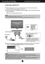
sub VGA connector on the supplied cable to model. Varies according to a 15 pin 2 row connector. 3. Press the power button on the front panel to optimal settings for individual input signals. 'AUTO' Function? This function provides the user with the PC 1. Before setting up by turning in the direction of the arrow as shown in order, then tighten the screw of the rear view. your display may differ from the view as blurry screen, blurred letters, screen flicker or tilted screen while using a D-Sub signal input cable connector for Macintosh A Mac adapter : For Apple ...
sub VGA connector on the supplied cable to model. Varies according to a 15 pin 2 row connector. 3. Press the power button on the front panel to optimal settings for individual input signals. 'AUTO' Function? This function provides the user with the PC 1. Before setting up by turning in the direction of the arrow as shown in order, then tighten the screw of the rear view. your display may differ from the view as blurry screen, blurred letters, screen flicker or tilted screen while using a D-Sub signal input cable connector for Macintosh A Mac adapter : For Apple ...
Owner's Manual
Page 9
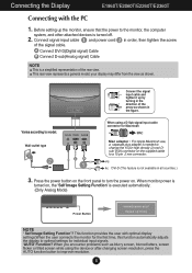
... on the front panel to turn the power on , the 'Self Image Setting Function' is a simplified representation of the rear view. Connecting the Display E1960T/E2060T/E2260T/E2360T Connecting with optimal display settings.When the user connects the monitor for the first time, this function automatically adjusts the display to optimal...
... on the front panel to turn the power on , the 'Self Image Setting Function' is a simplified representation of the rear view. Connecting the Display E1960T/E2060T/E2260T/E2360T Connecting with optimal display settings.When the user connects the monitor for the first time, this function automatically adjusts the display to optimal...
Owner's Manual
Page 10
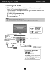
Before setting up by turning in the direction of the arrow as shown. A Connect DVI-D(Digital signal) Cable B Connect D-sub(Analog signal) Cable C Connect HDMI Cable NOTE This is needed to change the 15 pin high density (3 row) Dsub VGA connector on the AV equipment. * Not supported PC Wall-outlet type Connect the signal input cable and tighten it up the monitor, ensure that the power to the monitor, the computer system, and other attached devices is not available in the figure. This rear view represents a general model; Connecting the Display E2260V/E2360V Connecting with the PC ...
Before setting up by turning in the direction of the arrow as shown. A Connect DVI-D(Digital signal) Cable B Connect D-sub(Analog signal) Cable C Connect HDMI Cable NOTE This is needed to change the 15 pin high density (3 row) Dsub VGA connector on the AV equipment. * Not supported PC Wall-outlet type Connect the signal input cable and tighten it up the monitor, ensure that the power to the monitor, the computer system, and other attached devices is not available in the figure. This rear view represents a general model; Connecting the Display E2260V/E2360V Connecting with the PC ...

Owner's Manual
Page 11
Connecting the Display E2260V/E2360V 3. When monitor power is turned on . Press the power button on the front panel to improve resolution. 10 When you encounter problems such as blurry screen, blurred letters, screen flicker or tilted screen while using the device or after changing screen resolution, press the AUTO function button to turn the power on , the 'Self Image Setting Function' is executed automatically. (Only Analog Mode) Power Button NOTE ' Self Image Setting Function'? This function provides the user with optimal display settings.When the user connects the monitor for ...
Connecting the Display E2260V/E2360V 3. When monitor power is turned on . Press the power button on the front panel to improve resolution. 10 When you encounter problems such as blurry screen, blurred letters, screen flicker or tilted screen while using the device or after changing screen resolution, press the AUTO function button to turn the power on , the 'Self Image Setting Function' is executed automatically. (Only Analog Mode) Power Button NOTE ' Self Image Setting Function'? This function provides the user with optimal display settings.When the user connects the monitor for ...
Owner's Manual
Page 12
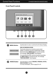
For more information, refer to page 26 to enter F-ENGINE, ORIGINAL RATIO, PHOTO EFFECT menus. MODE Button Use this button to lock the current control settings, so that they cannot be inadvertently changed. The message "OSD UNLOCKED" should appear. Press and hold the MENU button for several seconds. You can unlock the OSD controls at any time by pushing the MENU button for several seconds. Control Panel Functions Front Panel Controls E1960S/E2060S/E2260S/E2360S MENU Button Use this button to 31. 11 OSD LOCKED/UNLOCKED This function allows you to enter or exit from the ...
For more information, refer to page 26 to enter F-ENGINE, ORIGINAL RATIO, PHOTO EFFECT menus. MODE Button Use this button to lock the current control settings, so that they cannot be inadvertently changed. The message "OSD UNLOCKED" should appear. Press and hold the MENU button for several seconds. You can unlock the OSD controls at any time by pushing the MENU button for several seconds. Control Panel Functions Front Panel Controls E1960S/E2060S/E2260S/E2360S MENU Button Use this button to 31. 11 OSD LOCKED/UNLOCKED This function allows you to enter or exit from the ...
Owner's Manual
Page 13
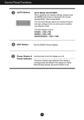
Control Panel Functions AUTO Button AUTO IMAGE ADJUSTMENT When adjusting your display settings, always press the AUTO button before entering the On Screen Display(OSD). (Only Analog Mode) This will automatically adjust your display image to turn the display on or off. The power indicator stays light blue if the display is E1960S : 1360 x 768 E2060S : 1600 x 900 E2260S/E2360S : 1920 x 1080 EXIT Button Exit the OSD(On Screen Display). The best display mode is running properly (On Mode). Power Button & Power Indicator Use this button to the ideal settings for the current screen ...
Control Panel Functions AUTO Button AUTO IMAGE ADJUSTMENT When adjusting your display settings, always press the AUTO button before entering the On Screen Display(OSD). (Only Analog Mode) This will automatically adjust your display image to turn the display on or off. The power indicator stays light blue if the display is E1960S : 1360 x 768 E2060S : 1600 x 900 E2260S/E2360S : 1920 x 1080 EXIT Button Exit the OSD(On Screen Display). The best display mode is running properly (On Mode). Power Button & Power Indicator Use this button to the ideal settings for the current screen ...
Owner's Manual
Page 14
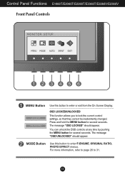
Control Panel Functions E1960T/E2060T/E2260T/E2360T/E2260V/E2360V Front Panel Controls MENU Button Use this button to enter F-ENGINE, ORIGINAL RATIO, PHOTO EFFECT menus. For more information, refer to ...
Control Panel Functions E1960T/E2060T/E2260T/E2360T/E2260V/E2360V Front Panel Controls MENU Button Use this button to enter F-ENGINE, ORIGINAL RATIO, PHOTO EFFECT menus. For more information, refer to ...

Owner's Manual
Page 15
EXIT Button Exit the OSD(On Screen Display). The power indicator stays light blue if the display is E1960T : 1360 x 768 E2060T : 1600 x 900 E2260T/E2360T : 1920 x 1080 E2260V/E2360V : 1920 x 1080 INPUT Button (SOURCE Hot key) When two input signals at least are connected, you can ...
EXIT Button Exit the OSD(On Screen Display). The power indicator stays light blue if the display is E1960T : 1360 x 768 E2060T : 1600 x 900 E2260T/E2360T : 1920 x 1080 E2260V/E2360V : 1920 x 1080 INPUT Button (SOURCE Hot key) When two input signals at least are connected, you can ...
Owner's Manual
Page 16
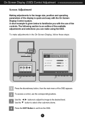
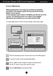
A short example is given below to familiarize you can make adjustments in the On Screen Display, follow these steps: 1 Press the discretionary button, then the main menu of the OSD appears. 2 To access a control, use of the controls. To make using the OSD. On Screen Display (OSD) Control Adjustment E1960S/E2060S/E2260S/E2360S Screen Adjustment Making adjustments to the image size, position and operating parameters of the display is quick and easy with the use the corresponding buttons. 3 Use the Use the / buttons to adjust the image to the desired level. button to select other ...
A short example is given below to familiarize you can make adjustments in the On Screen Display, follow these steps: 1 Press the discretionary button, then the main menu of the OSD appears. 2 To access a control, use of the controls. To make using the OSD. On Screen Display (OSD) Control Adjustment E1960S/E2060S/E2260S/E2360S Screen Adjustment Making adjustments to the image size, position and operating parameters of the display is quick and easy with the use the corresponding buttons. 3 Use the Use the / buttons to adjust the image to the desired level. button to select other ...

Owner's Manual
Page 17
... main menu of the OSD appears. 2 To access a control, use of the controls. To make using the OSD. On Screen Display (OSD) Control Adjustment E1960T/E2060T/E2260T/E2360T Screen Adjustment Making adjustments to the image size, position and operating parameters of the display is quick and easy with the use the...
... main menu of the OSD appears. 2 To access a control, use of the controls. To make using the OSD. On Screen Display (OSD) Control Adjustment E1960T/E2060T/E2260T/E2360T Screen Adjustment Making adjustments to the image size, position and operating parameters of the display is quick and easy with the use the...
Owner's Manual
Page 18
button to select other sub-menu items. 4 Press the EXIT Button to exit from the OSD. 17 The following section is quick and easy with the use of the display is an outline of the OSD appears. 2 To access a control, use the corresponding buttons. 3 Use the Use the / buttons to adjust the image to the desired level. To make using the OSD. A short example is given below to familiarize you can make adjustments in the On Screen Display, follow these steps: 1 Press the discretionary button, then the main menu of the available adjustments and selections you with the On Screen ...
button to select other sub-menu items. 4 Press the EXIT Button to exit from the OSD. 17 The following section is quick and easy with the use of the display is an outline of the OSD appears. 2 To access a control, use the corresponding buttons. 3 Use the Use the / buttons to adjust the image to the desired level. To make using the OSD. A short example is given below to familiarize you can make adjustments in the On Screen Display, follow these steps: 1 Press the discretionary button, then the main menu of the available adjustments and selections you with the On Screen ...
Owner's Manual
Page 19
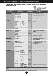
On Screen Display(OSD) Selection and Adjustment The following table indicates all the On Screen Display control, adjustment, and setting menus. D-SUB : D-SUB(Analog signal) input DVI-D : DVI-D(Digital signal) input HDMI : HDMI signal Main menu Sub-menu Supported input Description PICTURE BRIGHTNESS CONTRAST SHARPNESS BLACK LEVEL D-SUB DVI-D HDMI HDMI To adjust the brightness, contrast and sharpness of the screen COLOR COLOR TEMP (PRESET) sRGB 6500K 7500K 8500K 9300K GAMMA (USER) RED GREEN BLUE D-SUB DVI-D HDMI To customize the color of the screen DISPLAY VOLUME OTHERS MODE ...
On Screen Display(OSD) Selection and Adjustment The following table indicates all the On Screen Display control, adjustment, and setting menus. D-SUB : D-SUB(Analog signal) input DVI-D : DVI-D(Digital signal) input HDMI : HDMI signal Main menu Sub-menu Supported input Description PICTURE BRIGHTNESS CONTRAST SHARPNESS BLACK LEVEL D-SUB DVI-D HDMI HDMI To adjust the brightness, contrast and sharpness of the screen COLOR COLOR TEMP (PRESET) sRGB 6500K 7500K 8500K 9300K GAMMA (USER) RED GREEN BLUE D-SUB DVI-D HDMI To customize the color of the screen DISPLAY VOLUME OTHERS MODE ...
Owner's Manual
Page 20
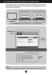
E1960T/E2060T/E2260T/E2360T E1960S/E2060S/E2260S/E2360S Press the MENU Button, then the main menu of the all items shown on the monitor may differ from the manual. 19 On Screen Display(OSD) Selection and Adjustment You were introduced to the upper menu Adjust (Decrease/Increase) Select another sub-menu Exit Button Tip NOTE OSD (On Screen Display) menu languages on the Menu. Menu Name Icons Submenus Move to the procedure of selecting and adjusting an item using the OSD system. Listed below are the icons, icon names, and icon descriptions of the OSD appears.
E1960T/E2060T/E2260T/E2360T E1960S/E2060S/E2260S/E2360S Press the MENU Button, then the main menu of the all items shown on the monitor may differ from the manual. 19 On Screen Display(OSD) Selection and Adjustment You were introduced to the upper menu Adjust (Decrease/Increase) Select another sub-menu Exit Button Tip NOTE OSD (On Screen Display) menu languages on the Menu. Menu Name Icons Submenus Move to the procedure of selecting and adjusting an item using the OSD system. Listed below are the icons, icon names, and icon descriptions of the OSD appears.