
Owner's Manual
Page 1
... for energy efficiency. www.lgusa.com / www.lg.ca S. See the label attached on the back cover and quote this information to your set. Environmental Protection Agency(EPA). LCD TV PLASMA TV OWNER'S MANUAL LCD TV MODELS 37LB5D 42LB5D 47LB5D 52LB5D 47LC7DF PLASMA TV MODELS 50PY3D 50PY3DF 60PY3D 60PY3DF Please read this product meets the ENERGY...
... for energy efficiency. www.lgusa.com / www.lg.ca S. See the label attached on the back cover and quote this information to your set. Environmental Protection Agency(EPA). LCD TV PLASMA TV OWNER'S MANUAL LCD TV MODELS 37LB5D 42LB5D 47LB5D 52LB5D 47LC7DF PLASMA TV MODELS 50PY3D 50PY3DF 60PY3D 60PY3DF Please read this product meets the ENERGY...
Owner's Manual
Page 3
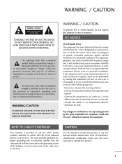
... without written authorization from that the cable ground shall be determined by turning the equipment off and on a circuit different from LG Electronics. FCC NOTICE Class B digital device This equipment has been tested and found to comply with arrowhead symbol, within an ...to persons. The exclamation point within the product's enclosure that interference will not occur in a residential installation. NOTE TO CABLE/TV INSTALLER This reminder is no guarantee that may cause harmful interference to rain or moisture. Unauthorized modification could void the user's ...
... without written authorization from that the cable ground shall be determined by turning the equipment off and on a circuit different from LG Electronics. FCC NOTICE Class B digital device This equipment has been tested and found to comply with arrowhead symbol, within an ...to persons. The exclamation point within the product's enclosure that interference will not occur in a residential installation. NOTE TO CABLE/TV INSTALLER This reminder is no guarantee that may cause harmful interference to rain or moisture. Unauthorized modification could void the user's ...
Owner's Manual
Page 6
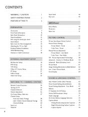
... 65 Preset Sound Setting (Sound Mode 66 Sound Setting Adjustment - Picture Improvement Technology 58 Advanced - User Mode 67 Balance 68 TV Speakers On/Off Setup 69 Stereo/SAP Broadcasts Setup 70 Audio Language 71 On-Screen Menus Language Selection 72 Caption Mode 73 -...62 Low - Auto Scan (Auto Tuning 38 - Preset 54 - Picture Mode - CONTENTS WARNING / CAUTION 1 SAFETY INSTRUCTIONS 2 FEATURE OF THIS TV 6 PREPARATION Accessories 7 Front Panel Information 8 Back Panel Information 10 Stand Installation 12 Not using the desk-type stand 13 Swivel Stand 13 Back...
... 65 Preset Sound Setting (Sound Mode 66 Sound Setting Adjustment - Picture Improvement Technology 58 Advanced - User Mode 67 Balance 68 TV Speakers On/Off Setup 69 Stereo/SAP Broadcasts Setup 70 Audio Language 71 On-Screen Menus Language Selection 72 Caption Mode 73 -...62 Low - Auto Scan (Auto Tuning 38 - Preset 54 - Picture Mode - CONTENTS WARNING / CAUTION 1 SAFETY INSTRUCTIONS 2 FEATURE OF THIS TV 6 PREPARATION Accessories 7 Front Panel Information 8 Back Panel Information 10 Stand Installation 12 Not using the desk-type stand 13 Swivel Stand 13 Back...
Owner's Manual
Page 7
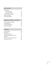
Auto Clock Setup 77 Manual Clock Setup 78 Auto On/Off Time Setting 79 Sleep Time Setting 80 Auto Shut-off Setting 81 PARENTAL CONTROL / RATINGS Set Password & Lock System 82 Channel Blocking 84 External Input Blocking 84 Movie & TV Rating 85 APPENDIX Troubleshooting 88 Maintenance 90 Product Specifications 91 Programming the Remote Control 93 IR Codes 97 External Control Through RS-232C 99 Open Source License 106 5 TIME SETTING Clock Setting -
Auto Clock Setup 77 Manual Clock Setup 78 Auto On/Off Time Setting 79 Sleep Time Setting 80 Auto Shut-off Setting 81 PARENTAL CONTROL / RATINGS Set Password & Lock System 82 Channel Blocking 84 External Input Blocking 84 Movie & TV Rating 85 APPENDIX Troubleshooting 88 Maintenance 90 Product Specifications 91 Programming the Remote Control 93 IR Codes 97 External Control Through RS-232C 99 Open Source License 106 5 TIME SETTING Clock Setting -
Owner's Manual
Page 8
... and sound. A subset of roughly a million or more pixels, 16:9 aspect-ratio screens, and AC3 digital audio. c. Disposal of mercury. LG TV with general household waste. This is normal, there is incorporated under license from a digital camera through the USB device. I Some minute dot defects...digital television, HDTV formats include 1080i and 720p resolutions. The fluorescent lamp used in accordance to the HDMI (high-definition multimedia interface), LG TV with this logo can play MP3 music from a MP3 player, such as tiny red, green, or blue spots. Do not dispose ...
... and sound. A subset of roughly a million or more pixels, 16:9 aspect-ratio screens, and AC3 digital audio. c. Disposal of mercury. LG TV with general household waste. This is normal, there is incorporated under license from a digital camera through the USB device. I Some minute dot defects...digital television, HDTV formats include 1080i and 720p resolutions. The fluorescent lamp used in accordance to the HDMI (high-definition multimedia interface), LG TV with this logo can play MP3 music from a MP3 player, such as tiny red, green, or blue spots. Do not dispose ...
Owner's Manual
Page 9
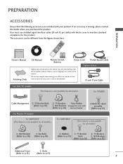
... Eye Bolts (Refer to p.16) (Refer to p.13) 7 Rubbers 2- Bolts (Refer to p.13) (Refer to p.16) 2- TV Bracket Bolts (Refer to maintain standard compliance for the product. User must use shielded signal interface cables (D-sub 15 pin cable) with your ... to p.16) the twist holder. 4-Bolts for all models) 2- TV Brackets, Twist Holder 2- D-sub 15 pin Cable For LCD TV models This feature is not available for stand assembly (Refer to p.16) 2- Wall Brackets 2- TV Brackets, 2- PREPARATION PREPARATION ACCESSORIES Ensure that excessive pressure may cause scratch ...
... Eye Bolts (Refer to p.16) (Refer to p.13) 7 Rubbers 2- Bolts (Refer to p.13) (Refer to p.16) 2- TV Bracket Bolts (Refer to maintain standard compliance for the product. User must use shielded signal interface cables (D-sub 15 pin cable) with your ... to p.16) the twist holder. 4-Bolts for all models) 2- TV Brackets, Twist Holder 2- D-sub 15 pin Cable For LCD TV models This feature is not available for stand assembly (Refer to p.16) 2- Wall Brackets 2- TV Brackets, 2- PREPARATION PREPARATION ACCESSORIES Ensure that excessive pressure may cause scratch ...
Owner's Manual
Page 10
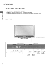
I Here shown may be somewhat different from your TV. And then wipe the product with a cloth (If a polishing cloth is switched on. Power/Standby Indicator Illuminates red in standby mode. Illuminates white when the set is included with your product, use it). Touch Pad ENTER INPUT Button ENTER VOLUME Button (F,G) Buttons POWER Button MENU Button CHANNEL (E,D) Buttons 8 PREPARATION FRONT PANEL INFORMATION I NOTE: If your product has a protection tape attached, remove the tape. Plasma TV Model PREPARATION Remote Control Sensor Program Display . .
I Here shown may be somewhat different from your TV. And then wipe the product with a cloth (If a polishing cloth is switched on. Power/Standby Indicator Illuminates red in standby mode. Illuminates white when the set is included with your product, use it). Touch Pad ENTER INPUT Button ENTER VOLUME Button (F,G) Buttons POWER Button MENU Button CHANNEL (E,D) Buttons 8 PREPARATION FRONT PANEL INFORMATION I NOTE: If your product has a protection tape attached, remove the tape. Plasma TV Model PREPARATION Remote Control Sensor Program Display . .
Owner's Manual
Page 11
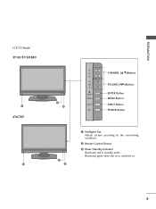
PREPARATION LCD TV Model 37/42/47/52LB5D 1 47LC7DF 1 2 3 CH CHANNEL (D,E)Buttons VOL VOLUME (F,G)Buttons ENTER MENU INPUT /I ENTER Button MENU Button INPUT Button POWER Button 2 3 1 Intelligent Eye Adjusts picture according to the surrounding conditions. 2 Remote Control Sensor 3 Power/Standby Indicator Illuminates red in standby mode. Illuminates green when the set is switched on. 9
PREPARATION LCD TV Model 37/42/47/52LB5D 1 47LC7DF 1 2 3 CH CHANNEL (D,E)Buttons VOL VOLUME (F,G)Buttons ENTER MENU INPUT /I ENTER Button MENU Button INPUT Button POWER Button 2 3 1 Intelligent Eye Adjusts picture according to the surrounding conditions. 2 Remote Control Sensor 3 Power/Standby Indicator Illuminates red in standby mode. Illuminates green when the set is switched on. 9
Owner's Manual
Page 13
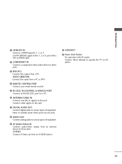
S-VIDEO Connect S-Video out from an external device to operate the TV on a PC. 6 ANTENNA/CABLE IN Connect over-the air signals to 1, 2 or 3. PREPARATION 1 HDMI/DVI IN Connect a HDMI signal to this jack. 7 DIGITAL AUDIO OUT ...
S-VIDEO Connect S-Video out from an external device to operate the TV on a PC. 6 ANTENNA/CABLE IN Connect over-the air signals to 1, 2 or 3. PREPARATION 1 HDMI/DVI IN Connect a HDMI signal to this jack. 7 DIGITAL AUDIO OUT ...
Owner's Manual
Page 14
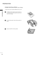
PREPARATION PREPARATION STAND INSTALLATION (Only 37LB5D) I Here shown may be somewhat different from your TV. 1 Carefully place the product screen side down on a cushioned surface that will protect product and screen from damage. 2 Assemble the product stand with the product as shown. 3 Securely install the 4 bolts provided. 12
PREPARATION PREPARATION STAND INSTALLATION (Only 37LB5D) I Here shown may be somewhat different from your TV. 1 Carefully place the product screen side down on a cushioned surface that will protect product and screen from damage. 2 Assemble the product stand with the product as shown. 3 Securely install the 4 bolts provided. 12
Owner's Manual
Page 15
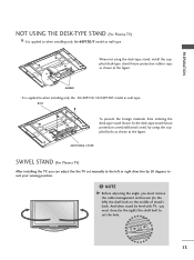
...supplied desk-type stand fixture protection rubber caps as wall-type. ADDITIONAL COVER SWIVEL STAND (For Plasma TV) After installing the TV, you must close (to the right) the shaft bolt to set manually to the left ) ...bolt on the middle of stand's back. NOTE G Before adjusting the angle, you can adjust the the TV set the hole. 13 When not using the supplied bolts as wall-type. BOLT To prevent the foreign ... position. ! PREPARATION NOT USING THE DESK-TYPE STAND (For Plasma TV) I It is applied to when installing only the 50/60PY3D, 50/60PY3DF model as shown at the figure.
...supplied desk-type stand fixture protection rubber caps as wall-type. ADDITIONAL COVER SWIVEL STAND (For Plasma TV) After installing the TV, you must close (to the right) the shaft bolt to set manually to the left ) ...bolt on the middle of stand's back. NOTE G Before adjusting the angle, you can adjust the the TV set the hole. 13 When not using the supplied bolts as wall-type. BOLT To prevent the foreign ... position. ! PREPARATION NOT USING THE DESK-TYPE STAND (For Plasma TV) I It is applied to when installing only the 50/60PY3D, 50/60PY3DF model as shown at the figure.
Owner's Manual
Page 16
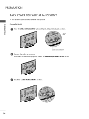
Plasma TV Model 1 Hold the CABLE MANAGEMENT with both hands and pull it backward as shown. 45° CABLE MANAGEMENT 2 Connect the cables as shown. 14 PREPARATION PREPARATION BACK COVER FOR WIRE ARRANGEMENT I Here shown may be somewhat different from your TV. To connect an additional equipment, see the EXTERNAL EQUIPMENT SETUP section. 3 Install the CABLE MANAGEMENT as necessary.
Plasma TV Model 1 Hold the CABLE MANAGEMENT with both hands and pull it backward as shown. 45° CABLE MANAGEMENT 2 Connect the cables as shown. 14 PREPARATION PREPARATION BACK COVER FOR WIRE ARRANGEMENT I Here shown may be somewhat different from your TV. To connect an additional equipment, see the EXTERNAL EQUIPMENT SETUP section. 3 Install the CABLE MANAGEMENT as necessary.
Owner's Manual
Page 17
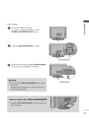
TWISTER HOLDER How to remove the CABLE MANAGEMENT G Hold the CABLE MANAGEMENT with both hands and pull it backward. 15 NOTE G Do not hold the CABLE MANAGEMENT when moving the product. - If the product is not available for all models.) CABLE MANAGEMENT ! To connect an additional equipment, see the EXTERNAL EQUIPMENT SETUP section. 2 Install the CABLE MANAGEMENT as necessary. PREPARATION LCD TV Model 1 Connect the cables as shown. 3 Bundle the cables using the supplied TWISTER HOLDER. (This feature is dropped, you may be injured or the product may be broken.
TWISTER HOLDER How to remove the CABLE MANAGEMENT G Hold the CABLE MANAGEMENT with both hands and pull it backward. 15 NOTE G Do not hold the CABLE MANAGEMENT when moving the product. - If the product is not available for all models.) CABLE MANAGEMENT ! To connect an additional equipment, see the EXTERNAL EQUIPMENT SETUP section. 2 Install the CABLE MANAGEMENT as necessary. PREPARATION LCD TV Model 1 Connect the cables as shown. 3 Bundle the cables using the supplied TWISTER HOLDER. (This feature is dropped, you may be injured or the product may be broken.
Owner's Manual
Page 18
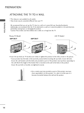
...wall brackets with the bolts (not provided as parts of the bracket that you set up the TV close to a wall so it cannot fall over if pushed backwards. Plasma TV Model 50PY3D/F 60PY3D/F LCD TV Model I This feature is safer to tie the rope so it cannot be somewhat different from the...) to tie the product. It is not available for all models. Ensure the eye-bolts or brackets are tightened securely. PREPARATION PREPARATION ATTACHING THE TV TO A WALL I Insert the eye-bolts (or TV brackets and bolts) to tighten the product to the wall as shown in the picture. * If your...
...wall brackets with the bolts (not provided as parts of the bracket that you set up the TV close to a wall so it cannot fall over if pushed backwards. Plasma TV Model 50PY3D/F 60PY3D/F LCD TV Model I This feature is safer to tie the rope so it cannot be somewhat different from the...) to tie the product. It is not available for all models. Ensure the eye-bolts or brackets are tightened securely. PREPARATION PREPARATION ATTACHING THE TV TO A WALL I Insert the eye-bolts (or TV brackets and bolts) to tighten the product to the wall as shown in the picture. * If your...
Owner's Manual
Page 19
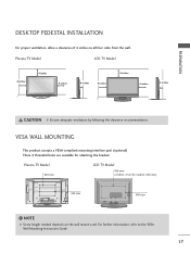
...) AV IN 2 USB S-VIDEO 400 mm 400 mm VIDEO L/MONO AUDIO R ! For further information, refer to the VESA Wall Mounting Instruction Guide. 17 Plasma TV Model LCD TV Model 4 inches 4 inches 4 inches 4 inches 4 inches 4 inches 4 inches 4 inches CAUTION G Ensure adequate ventilation by following the clearance recommendations. NOTE G Screw length needed depends on...
...) AV IN 2 USB S-VIDEO 400 mm 400 mm VIDEO L/MONO AUDIO R ! For further information, refer to the VESA Wall Mounting Instruction Guide. 17 Plasma TV Model LCD TV Model 4 inches 4 inches 4 inches 4 inches 4 inches 4 inches 4 inches 4 inches CAUTION G Ensure adequate ventilation by following the clearance recommendations. NOTE G Screw length needed depends on...
Owner's Manual
Page 20
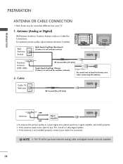
..., adjust antenna direction if needed. Wall Antenna Socket Multi-family Dwellings/Apartments (Connect to be somewhat different from your dealer for two TV's, install a 2-Way Signal Splitter. I To improve the picture quality in a poor signal area, please purchase a signal amplifier and ...install properly. PREPARATION PREPARATION ANTENNA OR CABLE CONNECTION I Here shown may be split for assistance. ( ) ! NOTE G The TV will let you know when the analog, cable, and digital channel scans are complete. 18 I If the antenna needs to wall antenna socket)...
..., adjust antenna direction if needed. Wall Antenna Socket Multi-family Dwellings/Apartments (Connect to be somewhat different from your dealer for two TV's, install a 2-Way Signal Splitter. I To improve the picture quality in a poor signal area, please purchase a signal amplifier and ...install properly. PREPARATION PREPARATION ANTENNA OR CABLE CONNECTION I Here shown may be split for assistance. ( ) ! NOTE G The TV will let you know when the analog, cable, and digital channel scans are complete. 18 I If the antenna needs to wall antenna socket)...
Owner's Manual
Page 21
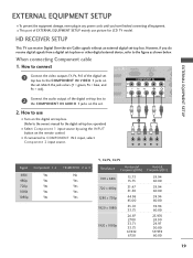
... colors (Y = green, PB = blue, and PR = red). 2 Connect the audio output of the digital set-top box to the owner's manual for LCD TV model. operation) I This part of EXTERNAL EQUIPMENT SETUP mainly use I If connected to the figure as shown below. COMPONENT IN 2 RS (CONTR 1 VIDEO AUDIO... S-V ( ) EXTERNAL EQUIPMENT SETUP 2. I Select Component 1 input source by using the INPUT button on the remote control. HD RECEIVER SETUP This TV can receive Digital Over-the-air/Cable signals without an external digital set-top box. How to use picture for the digital set-top box...
... colors (Y = green, PB = blue, and PR = red). 2 Connect the audio output of the digital set-top box to the owner's manual for LCD TV model. operation) I This part of EXTERNAL EQUIPMENT SETUP mainly use I If connected to the figure as shown below. COMPONENT IN 2 RS (CONTR 1 VIDEO AUDIO... S-V ( ) EXTERNAL EQUIPMENT SETUP 2. I Select Component 1 input source by using the INPUT button on the remote control. HD RECEIVER SETUP This TV can receive Digital Over-the-air/Cable signals without an external digital set-top box. How to use picture for the digital set-top box...
Owner's Manual
Page 24
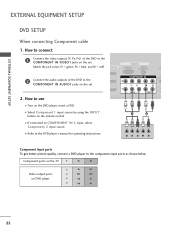
Component ports on the TV Y PB PR Video output ports on the set . How to the COMPONENT IN VIDEO1 jacks on the set . 2. How to connect 1 Connect the video outputs (Y, ...
Component ports on the TV Y PB PR Video output ports on the set . How to the COMPONENT IN VIDEO1 jacks on the set . 2. How to connect 1 Connect the video outputs (Y, ...
Owner's Manual
Page 26
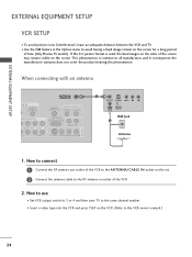
... of the screen may remain visible on the VCR. (Refer to the VCR owner's manual.) 24 ( ) I Set VCR output switch to 3 or 4 and then tune TV to all manufactures and in consequence the manufactures warranty does no( t )cover the product bearing this phenomenon. EXTERNAL EQUIPMENT SETUP EXTERNAL EQUIPMENT SETUP VCR SETUP... I Insert a video tape into the VCR and press PLAY on the screen. I To avoid picture noise (interference), leave an adequate distance between the VCR and TV. How to connect 1 Connect the RF antenna out socket of the VCR to the RF antenna in socket of time (Only Plasma...
... of the screen may remain visible on the VCR. (Refer to the VCR owner's manual.) 24 ( ) I Set VCR output switch to 3 or 4 and then tune TV to all manufactures and in consequence the manufactures warranty does no( t )cover the product bearing this phenomenon. EXTERNAL EQUIPMENT SETUP EXTERNAL EQUIPMENT SETUP VCR SETUP... I Insert a video tape into the VCR and press PLAY on the screen. I To avoid picture noise (interference), leave an adequate distance between the VCR and TV. How to connect 1 Connect the RF antenna out socket of the VCR to the RF antenna in socket of time (Only Plasma...
Owner's Manual
Page 27
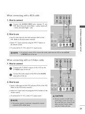
... A V 2 input source. ! AV IN 1 When connecting with a RCA cable ANT IN S-VIDEO VIDEO L R 1. CAUTION G Do not connect to connect 1 Connect the AUDIO/VIDEO jacks between TV and VCR.
... A V 2 input source. ! AV IN 1 When connecting with a RCA cable ANT IN S-VIDEO VIDEO L R 1. CAUTION G Do not connect to connect 1 Connect the AUDIO/VIDEO jacks between TV and VCR.


