Specification (English)
Page 1
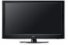
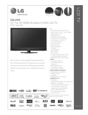
..., YouTube, and VUDU. Easy set up and use with NetCast™ Entertainment Access. LGusa.com LCD TV 55LH50 55" Full HD 1080p Broadband 120Hz LCD TV (54.6" diagonal) Tap into internet content easily and seamlessly with LG's first TV series with the Yahoo! TV • LG NetCast™ Entertainment Access* (Netflix®, YouTube™, Vudu™, Yahoo!® Widgets, My...
..., YouTube, and VUDU. Easy set up and use with NetCast™ Entertainment Access. LGusa.com LCD TV 55LH50 55" Full HD 1080p Broadband 120Hz LCD TV (54.6" diagonal) Tap into internet content easily and seamlessly with LG's first TV series with the Yahoo! TV • LG NetCast™ Entertainment Access* (Netflix®, YouTube™, Vudu™, Yahoo!® Widgets, My...
Specification (English)
Page 2
...• Quick Setup Guide • e-Manual • Parental Control w/V-Chip • Key Lock • Closed Caption • LG SIMPLINK (HDMI CEC) • CONVENIENCE FEATURES Language English/Spanish/French/Korean Auto Tuning/Programming • Channel Add/Delete • Channel...Mono/Stereo/Dual (MTS/SAP) • Audio Output Power (Watts - LCD TV 55LH50 55" Full HD 1080p Broadband 120Hz LCD TV (54.6" diagonal) LGusa.com LCD SPECIFICATION Screen Size (Class) 55" Class (54.6" diagonal) Native Display Resolution 1920 x 1080p Brightness (cd/m2) 500 ...
...• Quick Setup Guide • e-Manual • Parental Control w/V-Chip • Key Lock • Closed Caption • LG SIMPLINK (HDMI CEC) • CONVENIENCE FEATURES Language English/Spanish/French/Korean Auto Tuning/Programming • Channel Add/Delete • Channel...Mono/Stereo/Dual (MTS/SAP) • Audio Output Power (Watts - LCD TV 55LH50 55" Full HD 1080p Broadband 120Hz LCD TV (54.6" diagonal) LGusa.com LCD SPECIFICATION Screen Size (Class) 55" Class (54.6" diagonal) Native Display Resolution 1920 x 1080p Brightness (cd/m2) 500 ...
Owner's Manual (English)
Page 1
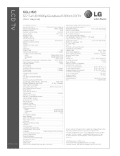
... product qualifies for ENERGY STAR. 1-800-243-0000 USA, Consumer User 1-888-865-3026 USA, Commercial User 1-888-542-2623 CANADA LG Customer Information Center Yahoo Support http://connectedtv.yahoo.com/help Netflix Support http://www.netflix.com/tvhelp YouTube Support http://www.youtube.com/t/contact_us....com Record it for future reference. The model and serial number of the TV is located on the back and one side of the TV. LCD TV PLASMA TV OWNER'S MANUAL LCD TV MODELS 42LH50 47LH50 55LH50 PLASMA TV MODELS 50PS80 60PS80 Please read this manual carefully before operating your set and retain...
... product qualifies for ENERGY STAR. 1-800-243-0000 USA, Consumer User 1-888-865-3026 USA, Commercial User 1-888-542-2623 CANADA LG Customer Information Center Yahoo Support http://connectedtv.yahoo.com/help Netflix Support http://www.netflix.com/tvhelp YouTube Support http://www.youtube.com/t/contact_us....com Record it for future reference. The model and serial number of the TV is located on the back and one side of the TV. LCD TV PLASMA TV OWNER'S MANUAL LCD TV MODELS 42LH50 47LH50 55LH50 PLASMA TV MODELS 50PS80 60PS80 Please read this manual carefully before operating your set and retain...
Owner's Manual (English)
Page 5
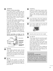
... places. 24 If you smell smoke or other odors coming from direct sunlight. 27 For LCD TV If the TV feels cold to the regulations of overhead power lines or other liquids directly on the TV as electric shock may be located in contact with hand or sharp object such as nail,... antenna system should not be a small "flicker" when it can occur. Do not clean with general household waste. ON DISPOSAL (Only Hg lamp used LCD TV) The fluorescent lamp used in accordance to the touch, there may occur. Do not install in the U.S.A. However, they have been removed. Disposal of ...
... places. 24 If you smell smoke or other odors coming from direct sunlight. 27 For LCD TV If the TV feels cold to the regulations of overhead power lines or other liquids directly on the TV as electric shock may be located in contact with hand or sharp object such as nail,... antenna system should not be a small "flicker" when it can occur. Do not clean with general household waste. ON DISPOSAL (Only Hg lamp used LCD TV) The fluorescent lamp used in accordance to the touch, there may occur. Do not install in the U.S.A. However, they have been removed. Disposal of ...
Owner's Manual (English)
Page 9
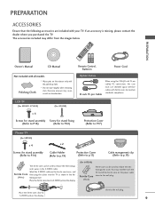
... plug. AV MODE Q. close to S-VIDEO jack on the ferrite core twice, and Ferrite Core then plug the cables into the TV as shown in the S-VIDEO cable. LCD TV (For 42LH50, 47LH50) (For 42LH50) x 4 Screws for stand assembly Screw for stand fixing (Refer to P.16) (Refer to... P.22) Protection Cover (Refer to P.17) Plasma TV (For 50PS80) x 4 x 2 Screws for stand assembly (Refer to P.14) Cable Holder (Refer to p.19) ...
... plug. AV MODE Q. close to S-VIDEO jack on the ferrite core twice, and Ferrite Core then plug the cables into the TV as shown in the S-VIDEO cable. LCD TV (For 42LH50, 47LH50) (For 42LH50) x 4 Screws for stand assembly Screw for stand fixing (Refer to P.16) (Refer to... P.22) Protection Cover (Refer to P.17) Plasma TV (For 50PS80) x 4 x 2 Screws for stand assembly (Refer to P.14) Cable Holder (Refer to p.19) ...
Owner's Manual (English)
Page 11
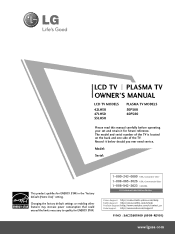
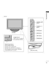
G p.141) CH VOL ENTER MENU INPUT CHANNEL (D,E) Buttons VOLUME (+, -) Buttons ENTER Button MENU Button INPUT Button POWER Button OFF ON Main power switch 11 PREPARATION LCD TV SPEAKER Intelligent Sensor Adjusts picture according to the surrounding conditions Remote Control Sensor, Power/Standby Indicator Illuminates red in the OPTION menu. Illuminates blue when the TV is switched on. (Can be adjusted using the Power Indicator in standby mode.
G p.141) CH VOL ENTER MENU INPUT CHANNEL (D,E) Buttons VOLUME (+, -) Buttons ENTER Button MENU Button INPUT Button POWER Button OFF ON Main power switch 11 PREPARATION LCD TV SPEAKER Intelligent Sensor Adjusts picture according to the surrounding conditions Remote Control Sensor, Power/Standby Indicator Illuminates red in the OPTION menu. Illuminates blue when the TV is switched on. (Can be adjusted using the Power Indicator in standby mode.
Owner's Manual (English)
Page 16
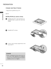
PREPARATION PREPARATION STAND INSTRUCTIONS I Image shown may differ from damage. 2 Assemble the TV as shown. 3 Fix the 4 screws securely using the holes in the back of the TV. ! Do not over tighten. 16 LCD TV INSTALLATION (For 42LH50, 47LH50) 1 Carefully place the TV screen side down on a cushioned surface to protect the screen from your TV. NOTE G When assembling the desk type stand, make sure the screws are fully tightened (If not tightened fully, the TV can tilt forward after the product installation).
PREPARATION PREPARATION STAND INSTRUCTIONS I Image shown may differ from damage. 2 Assemble the TV as shown. 3 Fix the 4 screws securely using the holes in the back of the TV. ! Do not over tighten. 16 LCD TV INSTALLATION (For 42LH50, 47LH50) 1 Carefully place the TV screen side down on a cushioned surface to protect the screen from your TV. NOTE G When assembling the desk type stand, make sure the screws are fully tightened (If not tightened fully, the TV can tilt forward after the product installation).
Owner's Manual (English)
Page 18
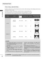
... VESA (A * B) A B Standard Screw Quantity Wall Mounting Bracket (sold separately) PREPARATION LCD TV 42LH50 47LH50 200 * 200 M6 55LH50 400 * 400 M6 4 AW-47LG30M 4 AW-55LH40M PLASMA TV 50PS80 400 * 400 M6 4 AW-50PG60MS 60PS80 600 * 400 M8 4 AW-60PG60MS ! G LG is not liable for TV damage or personal injury when a non-VESA or non specified wall...
... VESA (A * B) A B Standard Screw Quantity Wall Mounting Bracket (sold separately) PREPARATION LCD TV 42LH50 47LH50 200 * 200 M6 55LH50 400 * 400 M6 4 AW-47LG30M 4 AW-55LH40M PLASMA TV 50PS80 400 * 400 M6 4 AW-50PG60MS 60PS80 600 * 400 M8 4 AW-60PG60MS ! G LG is not liable for TV damage or personal injury when a non-VESA or non specified wall...
Owner's Manual (English)
Page 20
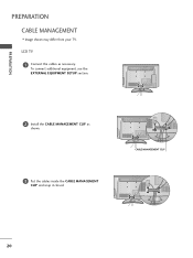
To connect additional equipment, see the EXTERNAL EQUIPMENT SETUP section. 2 Install the CABLE MANAGEMENT CLIP as necessary. CABLE MANAGEMENT CLIP 20 LCD TV 1 Connect the cables as shown. 3 Put the cables inside the CABLE MANAGEMENT CLIP and snap it closed. PREPARATION PREPARATION CABLE MANAGEMENT I Image shown may differ from your TV.
To connect additional equipment, see the EXTERNAL EQUIPMENT SETUP section. 2 Install the CABLE MANAGEMENT CLIP as necessary. CABLE MANAGEMENT CLIP 20 LCD TV 1 Connect the cables as shown. 3 Put the cables inside the CABLE MANAGEMENT CLIP and snap it closed. PREPARATION PREPARATION CABLE MANAGEMENT I Image shown may differ from your TV.
Owner's Manual (English)
Page 27
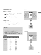
....00 59.94 60.00 23.976 24.00 29.97 30.00 59.94 60.00 EXTERNAL EQUIPMENT SETUP LCD TV AV IN 1 VIDEO L(MONO) AUDIO R 3 2 L R 1 EO AUDIO OMPONENT IN /DVI IN RGB... IN (PC) AUDIO IN OPT A (RGB/DVI) AN SERVICE ONLY CA () 1 HDMI OUTPUT Plasma TV ( ) 3 2 1 AU (R OPTICAL DIGITAL /DVI IN AUDIO OUT RGB IN (PC) R AUDIO L(MONO) VIDEO S-VIDEO LAN SERVICE AV ...1.3. In this case use I Select the HDMI1, HDMI2, HDMI3, or HDMI4 input source on the TV using the INPUT button on the remote control. ! No separate audio connection is necessary. 2 HDMI...
....00 59.94 60.00 23.976 24.00 29.97 30.00 59.94 60.00 EXTERNAL EQUIPMENT SETUP LCD TV AV IN 1 VIDEO L(MONO) AUDIO R 3 2 L R 1 EO AUDIO OMPONENT IN /DVI IN RGB... IN (PC) AUDIO IN OPT A (RGB/DVI) AN SERVICE ONLY CA () 1 HDMI OUTPUT Plasma TV ( ) 3 2 1 AU (R OPTICAL DIGITAL /DVI IN AUDIO OUT RGB IN (PC) R AUDIO L(MONO) VIDEO S-VIDEO LAN SERVICE AV ...1.3. In this case use I Select the HDMI1, HDMI2, HDMI3, or HDMI4 input source on the TV using the INPUT button on the remote control. ! No separate audio connection is necessary. 2 HDMI...
Owner's Manual (English)
Page 28
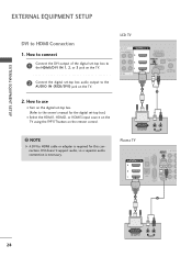
... -top box audio output to the HDMI/DVI IN 1, 2, or 3 jack on the TV. 2 Connect the digital set -top box.) I Select the HDMI1, HDMI2, or HDMI3 input source on the TV using the INPUT button on the remote control. ! LCD TV AV IN 1 L(MONO) AUDIO R 3 2 L R 1 AUDIO NT IN () /DVI IN... RGB IN (PC) AUDIO IN (RGB/DVI) OPTICAL DIGITA AUDIO OUT ANTENNA/ SERVICE ONLY CABLE IN 1 2 DVI OUTPUT L R AUDIO Plasma TV PR RGB IN (PC) ...
... -top box audio output to the HDMI/DVI IN 1, 2, or 3 jack on the TV. 2 Connect the digital set -top box.) I Select the HDMI1, HDMI2, or HDMI3 input source on the TV using the INPUT button on the remote control. ! LCD TV AV IN 1 L(MONO) AUDIO R 3 2 L R 1 AUDIO NT IN () /DVI IN... RGB IN (PC) AUDIO IN (RGB/DVI) OPTICAL DIGITA AUDIO OUT ANTENNA/ SERVICE ONLY CABLE IN 1 2 DVI OUTPUT L R AUDIO Plasma TV PR RGB IN (PC) ...
Owner's Manual (English)
Page 29
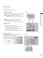
... the DVD player, insert a DVD. EXTERNAL EQUIPMENT SETUP DVD SETUP Component Connection 1. Match the jack colors (Y = green, PB = blue, and PR = red). LCD TV Y PB PR L R 2 Connect the audio outputs of the DVD to the COMPONENT IN AUDIO 1 jacks on DVD player Y PB PR Y B-Y R-Y Y Cb...CONT AUDIO 1 LA1N 2 R SERVICE AV IN 1 1 2 ONLY Y PB PR L R ( ) 29 I Select the Component1 input source on the TV using the INPUT button on the TV. How to connect 1 Connect the video outputs (Y, PB, PR) of the DVD to the COMPONENT IN VIDEO 1 jacks on the remote control.
... the DVD player, insert a DVD. EXTERNAL EQUIPMENT SETUP DVD SETUP Component Connection 1. Match the jack colors (Y = green, PB = blue, and PR = red). LCD TV Y PB PR L R 2 Connect the audio outputs of the DVD to the COMPONENT IN AUDIO 1 jacks on DVD player Y PB PR Y B-Y R-Y Y Cb...CONT AUDIO 1 LA1N 2 R SERVICE AV IN 1 1 2 ONLY Y PB PR L R ( ) 29 I Select the Component1 input source on the TV using the INPUT button on the TV. How to connect 1 Connect the video outputs (Y, PB, PR) of the DVD to the COMPONENT IN VIDEO 1 jacks on the remote control.
Owner's Manual (English)
Page 30
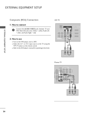
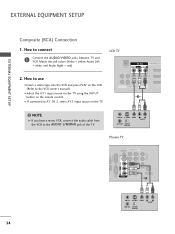
...control. I Refer to connect 1 Connect the AUDIO/VIDEO jacks between TV and DVD. EXTERNAL EQUIPMENT SETUP ( ) EXTERNAL EQUIPMENT SETUP Composite (RCA) Connection 1. Match the jack colors (Video = yellow, Audio Left = white, and Audio Right = red) 2. LCD TV AV IN 1 LAN VIDEO L(MONO) AUDIO R 3 2 2... L R 1 1 VIDEO AUDIO COMPONENT IN () 1 /DVI IN A ( VIDEO L R AUDIO Plasma TV AUDIO OUT ( ) AUDIO IN COMPONENT IN (RGB/DVI) L UT R Y VIDEO PB...
...control. I Refer to connect 1 Connect the AUDIO/VIDEO jacks between TV and DVD. EXTERNAL EQUIPMENT SETUP ( ) EXTERNAL EQUIPMENT SETUP Composite (RCA) Connection 1. Match the jack colors (Video = yellow, Audio Left = white, and Audio Right = red) 2. LCD TV AV IN 1 LAN VIDEO L(MONO) AUDIO R 3 2 2... L R 1 1 VIDEO AUDIO COMPONENT IN () 1 /DVI IN A ( VIDEO L R AUDIO Plasma TV AUDIO OUT ( ) AUDIO IN COMPONENT IN (RGB/DVI) L UT R Y VIDEO PB...
Owner's Manual (English)
Page 32
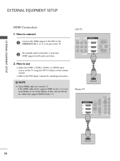
...DVD player's manual for operating instructions. ! How to the HDMI/DVI IN 1, 2, 3 or 4 jack on the remote control. NOTE G Check HDMI cable over version 1.3. LCD TV AV IN 1 VIDEO L(MONO) AUDIO R 3 2 L R 1 O AUDIO MPONENT IN /DVI IN RGB IN (PC) AUDIO IN (RGB/DVI) OPTIC AU ANT ...SERVICE ONLY CAB () 1 HDMI OUTPUT Plasma TV RGB IN (PC) R AUDIO L(MONO) VIDEO S-VIDEO OPTICAL DIGITAL /DVI IN AUDIO OUT 3 AUDIO IN COM (RGB/DVI) 2 1 LAN SERVICE AV IN 1 1 ONLY ...
...DVD player's manual for operating instructions. ! How to the HDMI/DVI IN 1, 2, 3 or 4 jack on the remote control. NOTE G Check HDMI cable over version 1.3. LCD TV AV IN 1 VIDEO L(MONO) AUDIO R 3 2 L R 1 O AUDIO MPONENT IN /DVI IN RGB IN (PC) AUDIO IN (RGB/DVI) OPTIC AU ANT ...SERVICE ONLY CAB () 1 HDMI OUTPUT Plasma TV RGB IN (PC) R AUDIO L(MONO) VIDEO S-VIDEO OPTICAL DIGITAL /DVI IN AUDIO OUT 3 AUDIO IN COM (RGB/DVI) 2 1 LAN SERVICE AV IN 1 1 ONLY ...
Owner's Manual (English)
Page 33
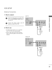
() EXTERNAL EQUIPMENT SETUP VCR SETUP Antenna Connection 1. How to the VCR owner's manual.) Plasma TV ANT OUT S-VIDEO VIDEO L R AUDIO ANT IN OUTPUT SWITCH Wall Jack 2 Antenna VIDEO ... ONLY CABLE IN 2. How to use I Insert a video tape into the VCR and press PLAY on the TV. UDIO IN OPTICAL DIGITAL AUDIO OUT GB/DVI) 1 2 Connect the antenna cable to the RF antenna in socket... I Set VCR output switch to 3 or 4 and then tune TV to the ANTENNA/CABLE IN sock- () RGB IN (PC) et on the VCR. (Refer to connect LCD TV 1 Connect the RF antenna out socket of the VCR.
() EXTERNAL EQUIPMENT SETUP VCR SETUP Antenna Connection 1. How to the VCR owner's manual.) Plasma TV ANT OUT S-VIDEO VIDEO L R AUDIO ANT IN OUTPUT SWITCH Wall Jack 2 Antenna VIDEO ... ONLY CABLE IN 2. How to use I Insert a video tape into the VCR and press PLAY on the TV. UDIO IN OPTICAL DIGITAL AUDIO OUT GB/DVI) 1 2 Connect the antenna cable to the RF antenna in socket... I Set VCR output switch to 3 or 4 and then tune TV to the ANTENNA/CABLE IN sock- () RGB IN (PC) et on the VCR. (Refer to connect LCD TV 1 Connect the RF antenna out socket of the VCR.
Owner's Manual (English)
Page 34
... input source on the TV using the INPUT button on the TV. 2 2 L R 1 1 VIDEO AUDIO COMPONENT IN 1 ! How to the AUDIO L/MONO jack of the TV. NOTE G If you have a mono VCR, connect the audio cable from the VCR to connect LCD TV 1 Connect the AUDIO/VIDEO jacks between TV and VCR. ANT IN... S-VIDEO VIDEO L R AUDIO ANT OUT OUTPUT SWITCH Plasma TV AUDIO OUT CAL TAL O OUT ( ) AUDIO IN COMPONENT IN (RGB/DVI) PB Y R VIDEO L PR...
... input source on the TV using the INPUT button on the TV. 2 2 L R 1 1 VIDEO AUDIO COMPONENT IN 1 ! How to the AUDIO L/MONO jack of the TV. NOTE G If you have a mono VCR, connect the audio cable from the VCR to connect LCD TV 1 Connect the AUDIO/VIDEO jacks between TV and VCR. ANT IN... S-VIDEO VIDEO L R AUDIO ANT OUT OUTPUT SWITCH Plasma TV AUDIO OUT CAL TAL O OUT ( ) AUDIO IN COMPONENT IN (RGB/DVI) PB Y R VIDEO L PR...
Owner's Manual (English)
Page 37
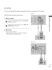
... connect 1 Connect the VGA output of the PC to use I Select the RGB-PC input source on the TV using the INPUT button on the PC and the TV. I Turn on the remote control. LCD TV 1 ( ) UDIO R 3 2 R 1 DIO /DVI IN RGB IN (PC) AUDIO IN (RGB/DVI) OPTICAL DIGITAL AUDIO OUT ...ANTENNA/ SERVICE ONLY CABLE IN Connect the PC audio output to the TV's settings. VGA (D-Sub 15 pin) Connection 1. EXTERNAL...
... connect 1 Connect the VGA output of the PC to use I Select the RGB-PC input source on the TV using the INPUT button on the PC and the TV. I Turn on the remote control. LCD TV 1 ( ) UDIO R 3 2 R 1 DIO /DVI IN RGB IN (PC) AUDIO IN (RGB/DVI) OPTICAL DIGITAL AUDIO OUT ...ANTENNA/ SERVICE ONLY CABLE IN Connect the PC audio output to the TV's settings. VGA (D-Sub 15 pin) Connection 1. EXTERNAL...
Owner's Manual (English)
Page 38
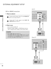
... SETUP DVI to use the latest cables that support HDMI version 1.3. I Turn on the TV. Connect the PC audio output to the HDMI/DVI IN 1, 2, or 3 jack on the PC and the TV. NOTE G Check HDMI cable over version 1.3. LCD TV AV IN 1 VIDEO L(MONO) AUDIO R 3 2 L R 1 O AUDIO MPONENT IN () .../DVI IN RGB IN (PC) AUDIO IN (RGB/DVI) OPTI AU ANT SERVICE ONLY CA 1 2 Plasma TV DVI OUTPUT AUDIO PR RGB IN (PC) R AUDIO ...
... SETUP DVI to use the latest cables that support HDMI version 1.3. I Turn on the TV. Connect the PC audio output to the HDMI/DVI IN 1, 2, or 3 jack on the PC and the TV. NOTE G Check HDMI cable over version 1.3. LCD TV AV IN 1 VIDEO L(MONO) AUDIO R 3 2 L R 1 O AUDIO MPONENT IN () .../DVI IN RGB IN (PC) AUDIO IN (RGB/DVI) OPTI AU ANT SERVICE ONLY CA 1 2 Plasma TV DVI OUTPUT AUDIO PR RGB IN (PC) R AUDIO ...
Owner's Manual (English)
Page 44
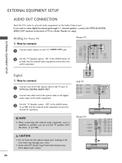
... digital audio input on the back of the optical cable to a Home Theater (or amp). See the external audio equipment instruction manual for operation. Plasma TV 3 2 1 RGB IN (PC) R AUDIO L(MONO) VIDEO S-VIDEO OPTICAL DIGITAL /DVI IN AUDIO OUT PB PR L 1 R LAN SERVICE AV IN ...AUDIO OUT terminal on the audio equipment. 3 Set the "TV Speaker option - L R AUDIO LCD TV ( ) 3 2 L R 1 AUDIO T IN AUDIO IN (RGB/DVI) OPTICAL DIGITAL AUDIO OUT AN1TENNA/ SERVICE ONLY CABLE IN 2 () ! Analog (For Plasma TV) 1. Plasma TV AUDIO OUT R OPTICAL DIGITAL VI IN AUDIO OUT AUDIO ...
... digital audio input on the back of the optical cable to a Home Theater (or amp). See the external audio equipment instruction manual for operation. Plasma TV 3 2 1 RGB IN (PC) R AUDIO L(MONO) VIDEO S-VIDEO OPTICAL DIGITAL /DVI IN AUDIO OUT PB PR L 1 R LAN SERVICE AV IN ...AUDIO OUT terminal on the audio equipment. 3 Set the "TV Speaker option - L R AUDIO LCD TV ( ) 3 2 L R 1 AUDIO T IN AUDIO IN (RGB/DVI) OPTICAL DIGITAL AUDIO OUT AN1TENNA/ SERVICE ONLY CABLE IN 2 () ! Analog (For Plasma TV) 1. Plasma TV AUDIO OUT R OPTICAL DIGITAL VI IN AUDIO OUT AUDIO ...
Owner's Manual (English)
Page 45
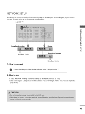
...the L A N port on the TV. 2. How to be connected to the LAN port. TV Widgets, Netflix, Vudu, YouTube, My Media) (G p.70-127). After making the physical connection, the TV needs to use the NetCast menu (Yahoo! EXTERNAL EQUIPMENT SETUP NETWORK SETUP This TV can be set up for network communication.... CAUTION G Do not connect a modular phone cable to a local area network (LAN) via the LAN port. i.e) LCD TV 1 AV IN 1 LAN VIDEO L(MONO) AUDIO R 3 2 2 L R 1 1 VIDEO AUDIO COMPONENT IN /DVI IN RGB IN (PC) AUDIO IN (RGB/DVI) ...
...the L A N port on the TV. 2. How to be connected to the LAN port. TV Widgets, Netflix, Vudu, YouTube, My Media) (G p.70-127). After making the physical connection, the TV needs to use the NetCast menu (Yahoo! EXTERNAL EQUIPMENT SETUP NETWORK SETUP This TV can be set up for network communication.... CAUTION G Do not connect a modular phone cable to a local area network (LAN) via the LAN port. i.e) LCD TV 1 AV IN 1 LAN VIDEO L(MONO) AUDIO R 3 2 2 L R 1 1 VIDEO AUDIO COMPONENT IN /DVI IN RGB IN (PC) AUDIO IN (RGB/DVI) ...


