Owner's Manual (English)
Page 1
...set of the set . www.lgusa.com / www.lg.ca S. has determined that this product meets the ENERGY STAR guidelines for future reference. A.,Inc. As an ENERGY STAR Partner LGE U. Record model number and serial number of power-saving guidelines issued by the U.S. LCD TV PLASMA TV OWNER'S MANUAL LCD TV MODELS 37LB5D 42LB5D 47LB5D 52LB5D 47LC7DF PLASMA TV... MODELS 50PY3D 50PY3DF 60PY3D 60PY3DF Please read this information to your set . Retain it for ...
...set of the set . www.lgusa.com / www.lg.ca S. has determined that this product meets the ENERGY STAR guidelines for future reference. A.,Inc. As an ENERGY STAR Partner LGE U. Record model number and serial number of power-saving guidelines issued by the U.S. LCD TV PLASMA TV OWNER'S MANUAL LCD TV MODELS 37LB5D 42LB5D 47LB5D 52LB5D 47LC7DF PLASMA TV... MODELS 50PY3D 50PY3DF 60PY3D 60PY3DF Please read this information to your set . Retain it for ...

Owner's Manual (English)
Page 6
... Label 44 Key Lock 45 MEDIAHOST MEDIAHOST Entry Modes 46 Photo List 47 Music List 51 PICTURE CONTROL Picture Size (Aspect Ratio) Control 53 Preset Picture Settings - Picture Mode - Picture Improvement Technology 58 Advanced - User Mode 67 Balance 68 TV Speakers On/Off Setup 69 Stereo/SAP Broadcasts Setup 70 Audio Language 71...
... Label 44 Key Lock 45 MEDIAHOST MEDIAHOST Entry Modes 46 Photo List 47 Music List 51 PICTURE CONTROL Picture Size (Aspect Ratio) Control 53 Preset Picture Settings - Picture Mode - Picture Improvement Technology 58 Advanced - User Mode 67 Balance 68 TV Speakers On/Off Setup 69 Stereo/SAP Broadcasts Setup 70 Audio Language 71...

Owner's Manual (English)
Page 7
TIME SETTING Clock Setting - Auto Clock Setup 77 Manual Clock Setup 78 Auto On/Off Time Setting 79 Sleep Time Setting 80 Auto Shut-off Setting 81 PARENTAL CONTROL / RATINGS Set Password & Lock System 82 Channel Blocking 84 External Input Blocking 84 Movie & TV Rating 85 APPENDIX Troubleshooting 88 Maintenance 90 Product Specifications 91 Programming the Remote Control 93 IR Codes 97 External Control Through RS-232C 99 Open Source License 106 5
TIME SETTING Clock Setting - Auto Clock Setup 77 Manual Clock Setup 78 Auto On/Off Time Setting 79 Sleep Time Setting 80 Auto Shut-off Setting 81 PARENTAL CONTROL / RATINGS Set Password & Lock System 82 Channel Blocking 84 External Input Blocking 84 Movie & TV Rating 85 APPENDIX Troubleshooting 88 Maintenance 90 Product Specifications 91 Programming the Remote Control 93 IR Codes 97 External Control Through RS-232C 99 Open Source License 106 5

Owner's Manual (English)
Page 10
Power/Standby Indicator Illuminates red in standby mode. I Here shown may be somewhat different from your TV. Plasma TV Model PREPARATION Remote Control Sensor Program Display . . Illuminates white when the set is included with a cloth (If a polishing cloth is switched on. Touch Pad ENTER INPUT Button ENTER VOLUME Button (F,G) Buttons POWER Button MENU Button CHANNEL (E,D) Buttons 8 PREPARATION FRONT PANEL INFORMATION I NOTE: If your product has a protection tape attached, remove the tape. And then wipe the product with your product, use it).
Power/Standby Indicator Illuminates red in standby mode. I Here shown may be somewhat different from your TV. Plasma TV Model PREPARATION Remote Control Sensor Program Display . . Illuminates white when the set is included with a cloth (If a polishing cloth is switched on. Touch Pad ENTER INPUT Button ENTER VOLUME Button (F,G) Buttons POWER Button MENU Button CHANNEL (E,D) Buttons 8 PREPARATION FRONT PANEL INFORMATION I NOTE: If your product has a protection tape attached, remove the tape. And then wipe the product with your product, use it).

Owner's Manual (English)
Page 11
Illuminates green when the set is switched on. 9 PREPARATION LCD TV Model 37/42/47/52LB5D 1 47LC7DF 1 2 3 CH CHANNEL (D,E)Buttons VOL VOLUME (F,G)Buttons ENTER MENU INPUT /I ENTER Button MENU Button INPUT Button POWER Button 2 3 1 Intelligent Eye Adjusts picture according to the surrounding conditions. 2 Remote Control Sensor 3 Power/Standby Indicator Illuminates red in standby mode.
Illuminates green when the set is switched on. 9 PREPARATION LCD TV Model 37/42/47/52LB5D 1 47LC7DF 1 2 3 CH CHANNEL (D,E)Buttons VOL VOLUME (F,G)Buttons ENTER MENU INPUT /I ENTER Button MENU Button INPUT Button POWER Button 2 3 1 Intelligent Eye Adjusts picture according to the surrounding conditions. 2 Remote Control Sensor 3 Power/Standby Indicator Illuminates red in standby mode.

Owner's Manual (English)
Page 15
...applied to when installing only the 60PY3D/F model as wall-type. ADDITIONAL COVER SWIVEL STAND (For Plasma TV) After installing the TV, you can adjust the the TV set the hole. 13 And when stand be level with TV, you must close (to the right) the shaft bolt to suit your viewing position. ! PREPARATION... NOT USING THE DESK-TYPE STAND (For Plasma TV) I It is applied to when installing only the 50/60PY3D, 50/60PY3DF ...
...applied to when installing only the 60PY3D/F model as wall-type. ADDITIONAL COVER SWIVEL STAND (For Plasma TV) After installing the TV, you can adjust the the TV set the hole. 13 And when stand be level with TV, you must close (to the right) the shaft bolt to suit your viewing position. ! PREPARATION... NOT USING THE DESK-TYPE STAND (For Plasma TV) I It is applied to when installing only the 50/60PY3D, 50/60PY3DF ...

Owner's Manual (English)
Page 18
... injury or damaging the product. I Use a sturdy rope (not provided as shown in the picture. * If your TV. Plasma TV Model 50PY3D/F 60PY3D/F LCD TV Model I Insert the eye-bolts (or TV brackets and bolts) to tighten the product to the wall as parts of the product, must purchase separately) to the... A WALL I This feature is safer to the wall. Additionally, we recommend that you set up the TV close to a wall so it cannot be somewhat different from the TV. We recommend that the TV be attached to a wall so it becomes horizontal between the wall and the product. 16 It ...
... injury or damaging the product. I Use a sturdy rope (not provided as shown in the picture. * If your TV. Plasma TV Model 50PY3D/F 60PY3D/F LCD TV Model I Insert the eye-bolts (or TV brackets and bolts) to tighten the product to the wall as parts of the product, must purchase separately) to the... A WALL I This feature is safer to the wall. Additionally, we recommend that you set up the TV close to a wall so it cannot be somewhat different from the TV. We recommend that the TV be attached to a wall so it becomes horizontal between the wall and the product. 16 It ...
Owner's Manual (English)
Page 21
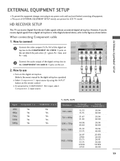
...). 2 Connect the audio output of EXTERNAL EQUIPMENT SETUP mainly use I If connected to the COMPONENT IN AUDIO 1 jacks on the digital set-top box. (Refer to the owner's manual for LCD TV model. COMPONENT IN 2 RS (CONTR 1 VIDEO AUDIO S-V ( ) EXTERNAL EQUIPMENT SETUP 2. However, if you have finished connecting all equipment. How to connect.../PB, CR/PR Resolution Horizontal Vertical Frequency(KHz) Frequency(Hz) 720 x 480i 720 x 480p 1280 x 720p 1920 x 1080i 1920 x 1080p 15.73 15.73 31.47 31.50 44.96 45.00 33.72 33.75 26.97 27.00 33.71 33.75 67.432 67.50 59.94 60...
...). 2 Connect the audio output of EXTERNAL EQUIPMENT SETUP mainly use I If connected to the COMPONENT IN AUDIO 1 jacks on the digital set-top box. (Refer to the owner's manual for LCD TV model. COMPONENT IN 2 RS (CONTR 1 VIDEO AUDIO S-V ( ) EXTERNAL EQUIPMENT SETUP 2. However, if you have finished connecting all equipment. How to connect.../PB, CR/PR Resolution Horizontal Vertical Frequency(KHz) Frequency(Hz) 720 x 480i 720 x 480p 1280 x 720p 1920 x 1080i 1920 x 1080p 15.73 15.73 31.47 31.50 44.96 45.00 33.72 33.75 26.97 27.00 33.71 33.75 67.432 67.50 59.94 60...

Owner's Manual (English)
Page 22
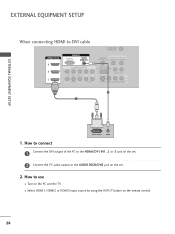
... IN RGB(PC) AUDIO (RGB/DV COMPONENT IN 2 1 1 VIDEO 1 HDMI-DTV OUTPUT HDMI-DTV mode Resolution Horizontal Frequency(KHz) Vertical Frequency(Hz) 720 x 480p 31.47 31.50 59.94 60.00 1280 x 720p 44.96 45.00 59.94 60.00 1920 x 1080i 33.72 33.75 59.94 60... is necessary. HDMI supports both audio and video. ( ) 2. How to use I Select HDMI1, HDMI2 or HDMI3 input source with using the INPUT button on the set -top box. (Refer to HDMI/DVI IN1, 2 or 3 jack on the remote control. EXTERNAL EQUIPMENT SETUP EXTERNAL EQUIPMENT SETUP When connecting HDMI cable 1.
... IN RGB(PC) AUDIO (RGB/DV COMPONENT IN 2 1 1 VIDEO 1 HDMI-DTV OUTPUT HDMI-DTV mode Resolution Horizontal Frequency(KHz) Vertical Frequency(Hz) 720 x 480p 31.47 31.50 59.94 60.00 1280 x 720p 44.96 45.00 59.94 60.00 1920 x 1080i 33.72 33.75 59.94 60... is necessary. HDMI supports both audio and video. ( ) 2. How to use I Select HDMI1, HDMI2 or HDMI3 input source with using the INPUT button on the set -top box. (Refer to HDMI/DVI IN1, 2 or 3 jack on the remote control. EXTERNAL EQUIPMENT SETUP EXTERNAL EQUIPMENT SETUP When connecting HDMI cable 1.
Owner's Manual (English)
Page 23
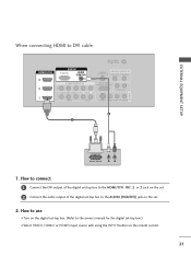
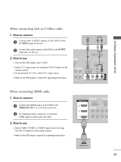
How to connect 1 Connect the DVI output of the digital set-top box to the HDMI/DVI IN1, 2 or 3 jack on the set. 2 Connect the audio output of the digital set . 2. EXTERNAL EQUIPMENT SETUP When connecting HDMI to the AUDIO (RGB/DVI) jack on the remote control. 21 How to use I Turn on the... digital set-top box. (Refer to the owner's manual for the digital set-top box.) I Select HDMI1, HDMI2 or HDMI3 input source with using the INPUT button on the set -top box to DVI cable HDMI/DVI IN 3 2 RGB IN RGB(PC...
How to connect 1 Connect the DVI output of the digital set-top box to the HDMI/DVI IN1, 2 or 3 jack on the set. 2 Connect the audio output of the digital set . 2. EXTERNAL EQUIPMENT SETUP When connecting HDMI to the AUDIO (RGB/DVI) jack on the remote control. 21 How to use I Turn on the... digital set-top box. (Refer to the owner's manual for the digital set-top box.) I Select HDMI1, HDMI2 or HDMI3 input source with using the INPUT button on the set -top box to DVI cable HDMI/DVI IN 3 2 RGB IN RGB(PC...

Owner's Manual (English)
Page 24
...to the component input ports as shown below. How to the COMPONENT IN AUDIO1 jacks on the DVD player, insert a DVD. Component ports on the TV Y PB PR Video output ports on the remote control. DVI IN RGB(PC) AUDIO (RGB/DVI) R CO 2 Connect the audio outputs of ...the DVD to the DVD player's manual for operating instructions. I Turn on the set . RGB IN Match the jack colors (Y = green, PB = blue, and PR = red). COMPONENT IN R (CONT 2 1 VIDEO AUDIO S- ( 1 2 Y PB PR L R Component Input ports ...
...to the component input ports as shown below. How to the COMPONENT IN AUDIO1 jacks on the DVD player, insert a DVD. Component ports on the TV Y PB PR Video output ports on the remote control. DVI IN RGB(PC) AUDIO (RGB/DVI) R CO 2 Connect the audio outputs of ...the DVD to the DVD player's manual for operating instructions. I Turn on the set . RGB IN Match the jack colors (Y = green, PB = blue, and PR = red). COMPONENT IN R (CONT 2 1 VIDEO AUDIO S- ( 1 2 Y PB PR L R Component Input ports ...
Owner's Manual (English)
Page 25
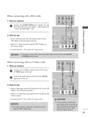
... manual for operating instructions. EXTERNAL EQUIPMENT SETUP When connecting with an S-Video cable 1. I Refer to the HDMI/DVI IN 1, 2, or 3 jack on the set. 2. How to connect 1 Connect the HDMI output of the DVD to the DVD player's manual for operating instructions. HDMI/DVI IN 3 2 RGB IN RGB...input source by using the INPUT button on the remote control. How to the AUDIO input jacks on the set . 2 Connect the audio outputs of the DVD to the S -VIDEO input on the set . 2 No separated audio connection is necessary. How to connect 1 Connect the S-VIDEO output of the...
... manual for operating instructions. EXTERNAL EQUIPMENT SETUP When connecting with an S-Video cable 1. I Refer to the HDMI/DVI IN 1, 2, or 3 jack on the set. 2. How to connect 1 Connect the HDMI output of the DVD to the DVD player's manual for operating instructions. HDMI/DVI IN 3 2 RGB IN RGB...input source by using the INPUT button on the remote control. How to the AUDIO input jacks on the set . 2 Connect the audio outputs of the DVD to the S -VIDEO input on the set . 2 No separated audio connection is necessary. How to connect 1 Connect the S-VIDEO output of the...
Owner's Manual (English)
Page 26
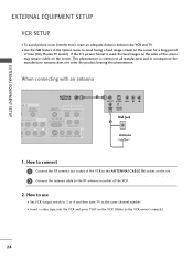
... the RF antenna out socket of the screen may remain visible on the set. 2 Connect the antenna cable to the same channel number. This phenomenon is used; I Set VCR output switch to 3 or 4 and then tune TV to the RF antenna in consequence the manufactures warranty does no( t )...cover the product bearing this phenomenon. I To avoid picture noise (interference), leave an adequate distance between the VCR and TV. the fixed images on ...
... the RF antenna out socket of the screen may remain visible on the set. 2 Connect the antenna cable to the same channel number. This phenomenon is used; I Set VCR output switch to 3 or 4 and then tune TV to the RF antenna in consequence the manufactures warranty does no( t )...cover the product bearing this phenomenon. I To avoid picture noise (interference), leave an adequate distance between the VCR and TV. the fixed images on ...
Owner's Manual (English)
Page 27
... IN (CONTROL & SERVICE) ( ) AUDIO OUT AUDIO S-VIDEO VIDEO (MONO) AUDIO ! ANT IN S-VIDEO VIDEO L R ANT OUT OUTPUT SWITCH 2 Connect the audio outputs of the set. In the event that you have a mono VCR, connect the audio cable from the VCR to the AUDIO L/MONO jack of the VCR to the... AUDIO input jacks on the set . I If connected to connect 1 Connect the AUDIO/VIDEO jacks between TV and VCR. AUDIO S-VIDEO VIDEO (MONO) AUDIO I If connected to the VCR owner's manual.) ANTENNA/ CABLE IN 1 REMOTE CONTROL ...
... IN (CONTROL & SERVICE) ( ) AUDIO OUT AUDIO S-VIDEO VIDEO (MONO) AUDIO ! ANT IN S-VIDEO VIDEO L R ANT OUT OUTPUT SWITCH 2 Connect the audio outputs of the set. In the event that you have a mono VCR, connect the audio cable from the VCR to the AUDIO L/MONO jack of the VCR to the... AUDIO input jacks on the set . I If connected to connect 1 Connect the AUDIO/VIDEO jacks between TV and VCR. AUDIO S-VIDEO VIDEO (MONO) AUDIO I If connected to the VCR owner's manual.) ANTENNA/ CABLE IN 1 REMOTE CONTROL ...

Owner's Manual (English)
Page 28
Match the jack colors. (Video = yellow, Audio Left = white, and Audio Right = red) 2. How to connect 1 Connect the AUDIO/VIDEO jacks between TV and external equipment. How to use I Select A V 2 input source by using the INPUT button on the remote control. I If connected to AV IN1 input, select A V 1 input source. VIDEO L/MONO AUDIO R Camcorder Video Game Set VIDEO L R USB IN S-VIDEO 1 AV IN 2 26 EXTERNAL EQUIPMENT SETUP EXTERNAL EQUIPMENT SETUP OTHER A/V SOURCE SETUP 1. I Operate the corresponding external equipment.
Match the jack colors. (Video = yellow, Audio Left = white, and Audio Right = red) 2. How to connect 1 Connect the AUDIO/VIDEO jacks between TV and external equipment. How to use I Select A V 2 input source by using the INPUT button on the remote control. I If connected to AV IN1 input, select A V 1 input source. VIDEO L/MONO AUDIO R Camcorder Video Game Set VIDEO L R USB IN S-VIDEO 1 AV IN 2 26 EXTERNAL EQUIPMENT SETUP EXTERNAL EQUIPMENT SETUP OTHER A/V SOURCE SETUP 1. I Operate the corresponding external equipment.
Owner's Manual (English)
Page 29
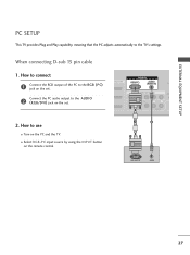
... to connect RGB IN 1 Connect the RGB output of the PC to use I Turn on the set . 1 VIDEO AUDIO ( ) 2. How to the RG B (P C) jack on the PC and the TV. PC SETUP This TV provides Plug and Play capability, meaning that the PC adjusts automatically to the AUDIO 2 2 (RGB... jack on the remote control. 1 2 RGB OUTPUT AUDIO ( 27 I Select RGB-PC input source by using the INPUT button on the set . I /DVI IN RGB(PC) AUDIO (RGB/DVI) CO COMPONENT IN (CO Connect the PC audio output to the TV's settings. EXTERNAL EQUIPMENT SETUP When connecting D-sub 15 pin cable 1.
... to connect RGB IN 1 Connect the RGB output of the PC to use I Turn on the set . 1 VIDEO AUDIO ( ) 2. How to the RG B (P C) jack on the PC and the TV. PC SETUP This TV provides Plug and Play capability, meaning that the PC adjusts automatically to the AUDIO 2 2 (RGB... jack on the remote control. 1 2 RGB OUTPUT AUDIO ( 27 I Select RGB-PC input source by using the INPUT button on the set . I /DVI IN RGB(PC) AUDIO (RGB/DVI) CO COMPONENT IN (CO Connect the PC audio output to the TV's settings. EXTERNAL EQUIPMENT SETUP When connecting D-sub 15 pin cable 1.
Owner's Manual (English)
Page 30
How to use I Select HDMI1, HDMI2 or HDMI3 input source by using the INPUT button on the remote control. 28 I Turn on the set . 2 Connect the PC audio output to DVI cable HDMI/DVI IN 3 2 RGB IN RGB(PC) AUDIO (RGB/DVI) COMPONENT IN 2 1 1 VIDEO AUDIO ANTENNA/ CABLE IN ... EQUIPMENT SETUP DVI-PC OUTPUT AUDIO 1. How to connect 1 Connect the DVI output of the PC to the HDMI/DVI IN1, 2 or 3 jack on the set . 2. EXTERNAL EQUIPMENT SETUP When connecting HDMI to the AUDIO (RGB/DVI) jack on the PC and the...
How to use I Select HDMI1, HDMI2 or HDMI3 input source by using the INPUT button on the remote control. 28 I Turn on the set . 2 Connect the PC audio output to DVI cable HDMI/DVI IN 3 2 RGB IN RGB(PC) AUDIO (RGB/DVI) COMPONENT IN 2 1 1 VIDEO AUDIO ANTENNA/ CABLE IN ... EQUIPMENT SETUP DVI-PC OUTPUT AUDIO 1. How to connect 1 Connect the DVI output of the PC to the HDMI/DVI IN1, 2 or 3 jack on the set . 2. EXTERNAL EQUIPMENT SETUP When connecting HDMI to the AUDIO (RGB/DVI) jack on the PC and the...

Owner's Manual (English)
Page 32
... the INPUT button on the remote control. EXTERNAL EQUIPMENT SETUP EXTERNAL EQUIPMENT SETUP Screen Setup for PC mode Overview When the RGB input, of the set is connected to the screen adjustment menu. 23 30
... the INPUT button on the remote control. EXTERNAL EQUIPMENT SETUP EXTERNAL EQUIPMENT SETUP Screen Setup for PC mode Overview When the RGB input, of the set is connected to the screen adjustment menu. 23 30

Owner's Manual (English)
Page 33
... allows you to minimize any horizontal noise and clear or sharpen the image of having the same H/V Sync Time. Resolution Position Size Phase Reset Initialize Settings Yes No MENU Prev F G Select OK 123 31 Size This function is you to make appropriate adjustments. This function is to remove any vertical bars...
... allows you to minimize any horizontal noise and clear or sharpen the image of having the same H/V Sync Time. Resolution Position Size Phase Reset Initialize Settings Yes No MENU Prev F G Select OK 123 31 Size This function is you to make appropriate adjustments. This function is to remove any vertical bars...
Owner's Manual (English)
Page 35
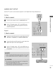
... or COAXIAL port of the optical or coaxial cable to the digital audio input on the audio equipment. 3 Set the "TV Speaker option - Off" in the AUDIO menu. (G p.69). See the external audio equipment instruction manual for operation. NOTE G When connecting with ACP(Audio ...to connect 1 Connect audio outputs to external audio equipment via the Digital Audio Output (Optical) port. EXTERNAL EQUIPMENT SETUP AUDIO OUT SETUP Send the TV's audio to the TV's AUDIO OUT jacks. 2 Set the "TV Speaker option - Off " in the AUDIO menu. (G p.69). Looking at the laser beam may damage your vision.
... or COAXIAL port of the optical or coaxial cable to the digital audio input on the audio equipment. 3 Set the "TV Speaker option - Off" in the AUDIO menu. (G p.69). See the external audio equipment instruction manual for operation. NOTE G When connecting with ACP(Audio ...to connect 1 Connect audio outputs to external audio equipment via the Digital Audio Output (Optical) port. EXTERNAL EQUIPMENT SETUP AUDIO OUT SETUP Send the TV's audio to the TV's AUDIO OUT jacks. 2 Set the "TV Speaker option - Off " in the AUDIO menu. (G p.69). Looking at the laser beam may damage your vision.


