Owners Manual
Page 2
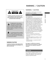
... uses and can be determined by turning the equipment off and on_ the user is con- - Consult the dealer or an experienced radio/TV technician for compliance could void the user's authority to operate this product to rain or moisture. These limits are C designed to provide reasonable... a pa_icular installation, if this product in accordance with the limits for a Class g digib[ device, purN suant to an outlet on a circuit from LG Electronics. Reorient or relocate the receiving antenna. the equipment to Pa_ ]5 of - WARNING / CAUTION WARN IN G/CAUTION TO REDUCE THE RISK OF FIRE...
... uses and can be determined by turning the equipment off and on_ the user is con- - Consult the dealer or an experienced radio/TV technician for compliance could void the user's authority to operate this product to rain or moisture. These limits are C designed to provide reasonable... a pa_icular installation, if this product in accordance with the limits for a Class g digib[ device, purN suant to an outlet on a circuit from LG Electronics. Reorient or relocate the receiving antenna. the equipment to Pa_ ]5 of - WARNING / CAUTION WARN IN G/CAUTION TO REDUCE THE RISK OF FIRE...
Owners Manual
Page 5
... 39-41 42-57 PIP/POP/Twin Picture - Moving the PIP Sub Picture 59 - POP (Picture-out-of-Picture: Channel Scan) .... 61 Turning the TV On 35 On-Screen Menus Language Selection .......... 36 Initial Channel Search (EZ Scan 37 Channel Selection 38 Volume Adjustment 38 4 Using TV Guide TV Guide On...-23 VCR Setup 24-25 b_VOut Setup 26 Digital Audio Output 27 ExternalA/V SourceSetup 28 DVD Setup 29-30 PC Setup 31 -34 TV Guide On Screen Setup Ready to Setup - Selecting an Input Signal Source for Twin Picture 60 - Adjusting Main and Sub Pi_ure Sizes ...
... 39-41 42-57 PIP/POP/Twin Picture - Moving the PIP Sub Picture 59 - POP (Picture-out-of-Picture: Channel Scan) .... 61 Turning the TV On 35 On-Screen Menus Language Selection .......... 36 Initial Channel Search (EZ Scan 37 Channel Selection 38 Volume Adjustment 38 4 Using TV Guide TV Guide On...-23 VCR Setup 24-25 b_VOut Setup 26 Digital Audio Output 27 ExternalA/V SourceSetup 28 DVD Setup 29-30 PC Setup 31 -34 TV Guide On Screen Setup Ready to Setup - Selecting an Input Signal Source for Twin Picture 60 - Adjusting Main and Sub Pi_ure Sizes ...
Owners Manual
Page 6
... SoundRite 79 Auto Sound Control (EZ Sound 80 Manual Sound Control (EZ Sound-User Option Balance 81-82 83 TV Speakers On/Off Setup 84 BBE 85 Stereo/SAP Broadcasts Setup 86 _me Setting Auto Clock Setup 87 Manual Clock Setup... Control 9 Programming Codes 120-122 Troubleshooting Checklist Maintenance 123-125 126 Product Specifications 127 After reading this manual keep it handy for USA only 104 TV Rating General- Cinema 3:2 Mode Setup 75 - Analog Broadcasting System Captions ......... 94 Digit[ Broadcasting System Captions ......... 95 N 0 Caption Option 96...
... SoundRite 79 Auto Sound Control (EZ Sound 80 Manual Sound Control (EZ Sound-User Option Balance 81-82 83 TV Speakers On/Off Setup 84 BBE 85 Stereo/SAP Broadcasts Setup 86 _me Setting Auto Clock Setup 87 Manual Clock Setup... Control 9 Programming Codes 120-122 Troubleshooting Checklist Maintenance 123-125 126 Product Specifications 127 After reading this manual keep it handy for USA only 104 TV Rating General- Cinema 3:2 Mode Setup 75 - Analog Broadcasting System Captions ......... 94 Digit[ Broadcasting System Captions ......... 95 N 0 Caption Option 96...
Owners Manual
Page 7
...display that you to view your own home. Our production technology minimizes these cell defects dur° ing the manufacture and operation of this Plasma TV is composed of 0_9 to 2.2 million cells, A few celt defects are easily viewable in your PC and video images simultaneously. This ...to a PC and use it easy to produce colored light (red, green, or blue). Several tiny, minute colored dots visible on the Plasma TV screen The Plasma TV is defective_ Thus a few cell defects will normally occur in -Picture feature allows you get perfect images that this product. 6 t H ...
...display that you to view your own home. Our production technology minimizes these cell defects dur° ing the manufacture and operation of this Plasma TV is composed of 0_9 to 2.2 million cells, A few celt defects are easily viewable in your PC and video images simultaneously. This ...to a PC and use it easy to produce colored light (red, green, or blue). Several tiny, minute colored dots visible on the Plasma TV screen The Plasma TV is defective_ Thus a few cell defects will normally occur in -Picture feature allows you get perfect images that this product. 6 t H ...
Owners Manual
Page 9
... operator enhanced prog_m (For example, electronic program guide provided by Gemstar_TV Guide International, Inc. For more of its affiliates. License Notice O The TV Guide On Screen _ system is protected by one or more informa_ lion con_ct your local cable operator. 8 and/or one of the following issued... Use of a set top box. A security card provided by direct connection to view encryp_d digital programming. In no event shall Gems_r-TV Guide International, Inc_ and/or its related affiliates are registered marks of the program schedule information or other data in the...
... operator enhanced prog_m (For example, electronic program guide provided by Gemstar_TV Guide International, Inc. For more of its affiliates. License Notice O The TV Guide On Screen _ system is protected by one or more informa_ lion con_ct your local cable operator. 8 and/or one of the following issued... Use of a set top box. A security card provided by direct connection to view encryp_d digital programming. In no event shall Gems_r-TV Guide International, Inc_ and/or its related affiliates are registered marks of the program schedule information or other data in the...
Owners Manual
Page 11
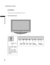
Front Panel Controls O C 8 Z iiiiiii__iii_iiiii_ii_ i_ii__iiiiiiiiiiiii!i Remote Control Sensor Power Standby Indicator llIuminates red in standby mode. POWER gutton iTV GUIDE Button INPUT Button [MENU [Button VOLUME CHANNEL (V,A)Buttons I0 CONTROLS Here shown may be somewhat different from your TV. When the TV is turned on, the indicator blinks white and then illuminates white before the picture is displayed.
Front Panel Controls O C 8 Z iiiiiii__iii_iiiii_ii_ i_ii__iiiiiiiiiiiii!i Remote Control Sensor Power Standby Indicator llIuminates red in standby mode. POWER gutton iTV GUIDE Button INPUT Button [MENU [Button VOLUME CHANNEL (V,A)Buttons I0 CONTROLS Here shown may be somewhat different from your TV. When the TV is turned on, the indicator blinks white and then illuminates white before the picture is displayed.
Owners Manual
Page 12
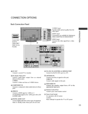
S VIDEO input Provides be_er picture quality than the video input. Connect a second TV or monitor, ® RS-232C IN (CONTROL & SERVICE) PORT Connect to the RS-232C port on DC power, 11 S-VIDEO output from an external Connect S-... these jacks. Note: In standby mode, these jacks. Or DVl(VlDEO)signal to the 1 (DVI) port with AC power, Caution: Never a_empt to operate the TV on a PC. _AV (AaadioiVideo) IN I Connect audio/video device to these ports do not work. @ ANTENNA IN Connect over-the air signals to this jack...
S VIDEO input Provides be_er picture quality than the video input. Connect a second TV or monitor, ® RS-232C IN (CONTROL & SERVICE) PORT Connect to the RS-232C port on DC power, 11 S-VIDEO output from an external Connect S-... these jacks. Note: In standby mode, these jacks. Or DVl(VlDEO)signal to the 1 (DVI) port with AC power, Caution: Never a_empt to operate the TV on a PC. _AV (AaadioiVideo) IN I Connect audio/video device to these ports do not work. @ ANTENNA IN Connect over-the air signals to this jack...
Owners Manual
Page 13
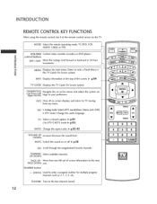
...) Navigate the on -screen displays and return to enter a program number for multiple program channels such as 2-1,2-2, etc. MUTE Switch the sound on the TV. MENU Displays the main menu. EXIT Clear all on -screen menus and adiust the system settings to the last channel viewed. O C 8 Z 12...control, aim it at the top of screen information PAGE DOWN one. Move from any menu. Move the Listings Grid forward or backward in the TV Guide On Screen system. SAP o Analog _e: _lects MTS _und(Mono, Stereo_and a SAP) DTV mode: Change the audio language. CHANNEL Select available...
...) Navigate the on -screen displays and return to enter a program number for multiple program channels such as 2-1,2-2, etc. MUTE Switch the sound on the TV. MENU Displays the main menu. EXIT Clear all on -screen menus and adiust the system settings to the last channel viewed. O C 8 Z 12...control, aim it at the top of screen information PAGE DOWN one. Move from any menu. Move the Listings Grid forward or backward in the TV Guide On Screen system. SAP o Analog _e: _lects MTS _und(Mono, Stereo_and a SAP) DTV mode: Change the audio language. CHANNEL Select available...

Owners Manual
Page 14
... In AV I °2, Component 1-2, RGB_PC (or RGB-DTV), HDMI]/DVl, and HDM[2 input sources, screen returns to the last TV channel. ADJUST Adjust the screen position, size, and phase in -4 regular sequence: An_nna, 0 Cable, AV]-2, Component 1-2, C RGB-PC (or RGB-DTV), t_ HDMI]/.... @ p.58-61 Changes the PiP channel. _ p.59 PiP iNPUT Select the connected sub°picture. _ p,59 input source for type of time before your TV or any other programmed equipment on or off automatically. @ p.90 APM Compare the Daylight, Normal, Night Time and User1 (or2) on the viewing environment. _ ...
... In AV I °2, Component 1-2, RGB_PC (or RGB-DTV), HDMI]/DVl, and HDM[2 input sources, screen returns to the last TV channel. ADJUST Adjust the screen position, size, and phase in -4 regular sequence: An_nna, 0 Cable, AV]-2, Component 1-2, C RGB-PC (or RGB-DTV), t_ HDMI]/.... @ p.58-61 Changes the PiP channel. _ p.59 PiP iNPUT Select the connected sub°picture. _ p,59 input source for type of time before your TV or any other programmed equipment on or off automatically. @ p.90 APM Compare the Daylight, Normal, Night Time and User1 (or2) on the viewing environment. _ ...

Owners Manual
Page 15
... are tightened securely. Secure the wall brackets with the bolts (not provided as parts of the product, must purchase separately) on or hang from the TV. Use a sturdy rope (not provided as shown in the picture. * If),our product has the bolts in a forward potentially causing injury or damaging ...the product. Caution: Please make sure that the TV be attached to tie the rope so it cannot be pulled in the eye-bolts position before inserting the eye-bolts, loosen the bolts. Additionally...
... are tightened securely. Secure the wall brackets with the bolts (not provided as parts of the product, must purchase separately) on or hang from the TV. Use a sturdy rope (not provided as shown in the picture. * If),our product has the bolts in a forward potentially causing injury or damaging ...the product. Caution: Please make sure that the TV be attached to tie the rope so it cannot be pulled in the eye-bolts position before inserting the eye-bolts, loosen the bolts. Additionally...
Owners Manual
Page 18
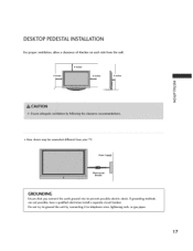
i Z r-Fi 0 Z Here shown may be somewhat different from the wall. Power Supply Ensure that you connect the earth ground wire to telephone wires, lightening rods, or gas pipes. 17 Do not try to ground the unit by connecting it to prevent possible electric shock. If grounding methods are not possible, have a qualified electrician install a separate circuit breaker. DESKTOP PEDESTALINSTALLATION For proper ventilation, allow a clearance of 4inches on each side from your TV.
i Z r-Fi 0 Z Here shown may be somewhat different from the wall. Power Supply Ensure that you connect the earth ground wire to telephone wires, lightening rods, or gas pipes. 17 Do not try to ground the unit by connecting it to prevent possible electric shock. If grounding methods are not possible, have a qualified electrician install a separate circuit breaker. DESKTOP PEDESTALINSTALLATION For proper ventilation, allow a clearance of 4inches on each side from your TV.
Owners Manual
Page 19
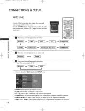
... set-top box depend on connector. Press the ENTER button to change the main input to AV 2) ! HDMI1/DVI, HDMI2: Select it when watching the TV/DTV. Antennal 1 _ ! E Antenna: Select it when using the DVD or the Digital set -top box depend on the screen. t,_.51.2Deno,_! 06/9/2 10:21 _ Page...
... set-top box depend on connector. Press the ENTER button to change the main input to AV 2) ! HDMI1/DVI, HDMI2: Select it when watching the TV/DTV. Antennal 1 _ ! E Antenna: Select it when using the DVD or the Digital set -top box depend on the screen. t,_.51.2Deno,_! 06/9/2 10:21 _ Page...
Owners Manual
Page 21
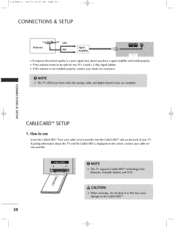
... the CableCARD _'_slot on the screen, contact your cable ser- 20 t_ O Z Z m N -4 Z m -4 c CABLECARDTM SETUP 1. If pairing information vice provider. How to be split for two TV's, install a 2-Way Signal Splitter. [f the antenna is displayed on the back of your dealer for assistance. about this...
... the CableCARD _'_slot on the screen, contact your cable ser- 20 t_ O Z Z m N -4 Z m -4 c CABLECARDTM SETUP 1. If pairing information vice provider. How to be split for two TV's, install a 2-Way Signal Splitter. [f the antenna is displayed on the back of your dealer for assistance. about this...
Owners Manual
Page 22
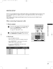
... box to COMPONENT IN2 input, select COMPONENT 2 input source. blue, and PR -- t,_,_512Deno,_Z 06/9/2 10:21 _ Page 2] HDSTB SETUP This TV can receive Digital Over-the-air/Cable do receive digital signals from a digital set -top box.) m Select COMPONENT 1 input source with using the INPUT... the digital set -top shown below. red). -4 O Z O Connect the audio output of the digital set O Z top box to the figure as This TV supports HDCP (High-bandwidth (480p,720p, 10801). If connected to the COMPONENT IN AUDIO 1 jacks on the set m -4 C 2. However, if you to the...
... box to COMPONENT IN2 input, select COMPONENT 2 input source. blue, and PR -- t,_,_512Deno,_Z 06/9/2 10:21 _ Page 2] HDSTB SETUP This TV can receive Digital Over-the-air/Cable do receive digital signals from a digital set -top box.) m Select COMPONENT 1 input source with using the INPUT... the digital set -top shown below. red). -4 O Z O Connect the audio output of the digital set O Z top box to the figure as This TV supports HDCP (High-bandwidth (480p,720p, 10801). If connected to the COMPONENT IN AUDIO 1 jacks on the set m -4 C 2. However, if you to the...
Owners Manual
Page 25
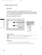
How to use Set VCR output switch to 3 or 4 and then tune TV to the VCR owner% manual.) 24 Connect the antenna cable to the RF antenna in socket of the screen may remain visible on the screen. ... time. t,_,_5lr2Den°,_! 06/9/2 10:21 _ Page 24 CONNECTIONS & SETUP VCR SETUP To avoid picture noise (interference), leave an adequate distance between the VCR and TV Use the ISM feature in the Option menu to avoid having a fixed image remain on the screen for a long period of the VCR to the...
How to use Set VCR output switch to 3 or 4 and then tune TV to the VCR owner% manual.) 24 Connect the antenna cable to the RF antenna in socket of the screen may remain visible on the screen. ... time. t,_,_5lr2Den°,_! 06/9/2 10:21 _ Page 24 CONNECTIONS & SETUP VCR SETUP To avoid picture noise (interference), leave an adequate distance between the VCR and TV Use the ISM feature in the Option menu to avoid having a fixed image remain on the screen for a long period of the VCR to the...
Owners Manual
Page 26
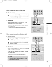
... input source. Match the jack colors (Video _ yellow, Audio Left white, and Audio Right _ red) 2. If connected to connect O onnect the AUDIO/VIDEO jacks between TV and VCR. How to AV IN2, select AV2 input source. 2S m N -4 O Z m -4 When connecting with a P.CA cable 1. How to connect O S-oVnIDneEcOt thienpuSt-VoInDEthOe soeutt.put of...
... input source. Match the jack colors (Video _ yellow, Audio Left white, and Audio Right _ red) 2. If connected to connect O onnect the AUDIO/VIDEO jacks between TV and VCR. How to AV IN2, select AV2 input source. 2S m N -4 O Z m -4 When connecting with a P.CA cable 1. How to connect O S-oVnIDneEcOt thienpuSt-VoInDEthOe soeutt.put of...
Owners Manual
Page 27
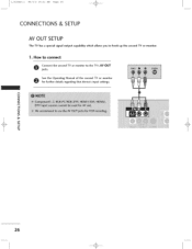
Sfoere futrhteherOpedreattainilsg reMgaarnduinagl othf atthedevsiecceo'snd inTpVut osrettminognsi.tor N 0 z Z m N -4 z m -4 c _!i!i_i_i_iii!i__ii!__ii_!_!_i!i__i!_i!_!_i!_i!_i!_i!_!_i!ii!i!!!_i 26 t,_,_51.2Deno,_! 06/9/2 10:21 _ Page 26 CONNECTIONS & SETUP AV OUT SETUP The TV has a special signal output capability which allows you to the TV's AV OUT O jacks. How to connect Connect the second TV or monitor to hook up the second TV or monitor. 1.
Sfoere futrhteherOpedreattainilsg reMgaarnduinagl othf atthedevsiecceo'snd inTpVut osrettminognsi.tor N 0 z Z m N -4 z m -4 c _!i!i_i_i_iii!i__ii!__ii_!_!_i!i__i!_i!_!_i!_i!_i!_i!_!_i!ii!i!!!_i 26 t,_,_51.2Deno,_! 06/9/2 10:21 _ Page 26 CONNECTIONS & SETUP AV OUT SETUP The TV has a special signal output capability which allows you to the TV's AV OUT O jacks. How to connect Connect the second TV or monitor to hook up the second TV or monitor. 1.

Owners Manual
Page 28
See the external audio equipment N O instruction manual for operation. t,_,_51.2Deno,_! 06/9/2 10:21 _ Page 2'7 DIGITAL AUDIO OUTPUT Send the TV's audio to the digital audio (optical) input on the audio equipment 0 Set the "TV Speaker option o Off" in the AUDIO menu. (_ p.84). How to connect O CAuodninoec(tOpotniceale) ndOuotfpaunt oppotirct.al cable to the TV Digital Connect the other end of the optical cable to external audio equipment via the Digital Audio Output (Optical) port, 1. Z Z m t_ -4 O Z m -4 C 27
See the external audio equipment N O instruction manual for operation. t,_,_51.2Deno,_! 06/9/2 10:21 _ Page 2'7 DIGITAL AUDIO OUTPUT Send the TV's audio to the digital audio (optical) input on the audio equipment 0 Set the "TV Speaker option o Off" in the AUDIO menu. (_ p.84). How to connect O CAuodninoec(tOpotniceale) ndOuotfpaunt oppotirct.al cable to the TV Digital Connect the other end of the optical cable to external audio equipment via the Digital Audio Output (Optical) port, 1. Z Z m t_ -4 O Z m -4 C 27

Owners Manual
Page 29
How to AV IN2 input, select AV2 Z input source. Operate the corresponding external equipment. m c Video Game S_ 28 Match the iack colors. (Video = yellow, Audio Left = white, and Audio Right = r_) Camcorder N 2. Howto use 0 Z Z SelectAV1 input source with usingthe m INPUT button on the remote control. If connected to connect O Connect the AUDIO/VIDEO jacks between TV and external equipment. t,_,_51,2Deno,_! 06/9/2 10:21 _ Page 28 CONNECTIONS & SETUP EXTERNAL _V SOURCE SETUP 1.
How to AV IN2 input, select AV2 Z input source. Operate the corresponding external equipment. m c Video Game S_ 28 Match the iack colors. (Video = yellow, Audio Left = white, and Audio Right = r_) Camcorder N 2. Howto use 0 Z Z SelectAV1 input source with usingthe m INPUT button on the remote control. If connected to connect O Connect the AUDIO/VIDEO jacks between TV and external equipment. t,_,_51,2Deno,_! 06/9/2 10:21 _ Page 28 CONNECTIONS & SETUP EXTERNAL _V SOURCE SETUP 1.
Owners Manual
Page 30
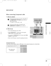
IN 2 input, select COM- I Component ports on the TV Video output ports on the remote control. If connected to the component input ports as shown below. Component Input ports To get better picture quality, ...
IN 2 input, select COM- I Component ports on the TV Video output ports on the remote control. If connected to the component input ports as shown below. Component Input ports To get better picture quality, ...


