
Owners Manual
Page 1
... increase power consumption that could exceed the limits necessary to quality for ENERGY STARin the "factory default (Home Use)" setting. Life's Good LCD TV OWNER'S MANUAL 32LH250H 37LH250H 42LH250H 32LH25SH 37LH25SH 42LH255H please read this manual carefully your set . before operating of the set . Retain it for future refi Record mode[ See...
... increase power consumption that could exceed the limits necessary to quality for ENERGY STARin the "factory default (Home Use)" setting. Life's Good LCD TV OWNER'S MANUAL 32LH250H 37LH250H 42LH250H 32LH25SH 37LH25SH 42LH255H please read this manual carefully your set . before operating of the set . Retain it for future refi Record mode[ See...

Owners Manual
Page 2
...does cause harmful interference to radio or television reception, which the receiver is connected. -Consult the dealer or an experienced radio/TV technician for compliance could void the user's authority to operate this product REFERTO QUALIFIED SERVICE PERSONNEL. DO NOT EXPOSE THIS PRODUCT TO...not occur in particular, specifies that may not cause (harmful) interference, and (2) this device must accept any way without written authorization from LG Electronics. However, there is subject to the point of the cable entry as practical. WARNING / CAUTION WARNING / CAUTION To prevent fire...
...does cause harmful interference to radio or television reception, which the receiver is connected. -Consult the dealer or an experienced radio/TV technician for compliance could void the user's authority to operate this product REFERTO QUALIFIED SERVICE PERSONNEL. DO NOT EXPOSE THIS PRODUCT TO...not occur in particular, specifies that may not cause (harmful) interference, and (2) this device must accept any way without written authorization from LG Electronics. However, there is subject to the point of the cable entry as practical. WARNING / CAUTION WARNING / CAUTION To prevent fire...
Owners Manual
Page 4
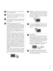
...FROM MAINS Mains plug is , a single outlet circuit which powers only that is the disconnecting device. Do not make sure not to install the TV by an authorized servicer. O GROUNDING Ensure that appliances be certain. O WARNING - Periodically examine the cord of these conditions could result in electric... shock or fire. Do not use of the TV. ® Do not allow an impact shock or any objects to fall into the product, and do not place objects filled with something....
...FROM MAINS Mains plug is , a single outlet circuit which powers only that is the disconnecting device. Do not make sure not to install the TV by an authorized servicer. O GROUNDING Ensure that appliances be certain. O WARNING - Periodically examine the cord of these conditions could result in electric... shock or fire. Do not use of the TV. ® Do not allow an impact shock or any objects to fall into the product, and do not place objects filled with something....

Owners Manual
Page 5
... of time. Do not spray water or other materials (e.g.) plastic while plugged in contact with cloth or other liquids directly on the TV as death or serious injury can occur. O Ventilation Install your finger(s) against voltage surges and built-up static charges. However, they...antenna system should not be visible on the screen, appearing as a bookcase. Do not install in the U.S.A_provides information with TV. For LCD TV If the TV feels cold to prevent scratching. Section 810 of overhead power lines or other odors coming from direct sunlight. ANTENNAS Outdoor antenna...
... of time. Do not spray water or other materials (e.g.) plastic while plugged in contact with cloth or other liquids directly on the TV as death or serious injury can occur. O Ventilation Install your finger(s) against voltage surges and built-up static charges. However, they...antenna system should not be visible on the screen, appearing as a bookcase. Do not install in the U.S.A_provides information with TV. For LCD TV If the TV feels cold to prevent scratching. Section 810 of overhead power lines or other odors coming from direct sunlight. ANTENNAS Outdoor antenna...
Owners Manual
Page 6
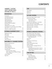
... Tuning) ...... 3;9 - User Mode .......... 56 Picture Improvement Technology 57 Advanced Control- SRSTruSurround XT 65 Clear Voice 66 Balance 67 TV Speakers On/Off Setup 68 Audio Reset 69 Stereo/SAP Broadcast Setup 70 Audio Language 71 On-Screen Menus Language Selection 72 Caption Mode... - CONTENTS WARNING / CAUTION 1 SAFETY INSTRUCTIONS 2 FEATURES OF THIS TV 7 Accessories 8 Front Panel Information 9 Back Panel Information 10 Stand Instruction 12 VESA Wall Mounting 14 Cable Management 15 Desktop ...
... Tuning) ...... 3;9 - User Mode .......... 56 Picture Improvement Technology 57 Advanced Control- SRSTruSurround XT 65 Clear Voice 66 Balance 67 TV Speakers On/Off Setup 68 Audio Reset 69 Stereo/SAP Broadcast Setup 70 Audio Language 71 On-Screen Menus Language Selection 72 Caption Mode... - CONTENTS WARNING / CAUTION 1 SAFETY INSTRUCTIONS 2 FEATURES OF THIS TV 7 Accessories 8 Front Panel Information 9 Back Panel Information 10 Stand Instruction 12 VESA Wall Mounting 14 Cable Management 15 Desktop ...

Owners Manual
Page 8
...when background noise swells. inv,s,ble h. High-definition television. Speakers are trademarks of human voice frequency range to music on your TV through USB 2.0 ('videos' dependent on model). sfs TruSurround XT S[S_is a trademark of digital television, HDTV formats include 1080i... and 720p resolutions. A subset of SRS Labs, Inc. SPEAKER.=I LG TV include a unique invisible speaker system, tuned by increasing the "sweet spot': giving a wider and richer sound field. under license from SRS ...
...when background noise swells. inv,s,ble h. High-definition television. Speakers are trademarks of human voice frequency range to music on your TV through USB 2.0 ('videos' dependent on model). sfs TruSurround XT S[S_is a trademark of digital television, HDTV formats include 1080i... and 720p resolutions. A subset of SRS Labs, Inc. SPEAKER.=I LG TV include a unique invisible speaker system, tuned by increasing the "sweet spot': giving a wider and richer sound field. under license from SRS ...
Owners Manual
Page 9
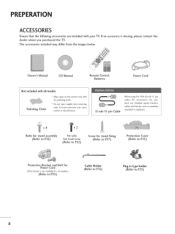
... the images below. PREPERATION ACCESSORIES Ensure that the following accessories are included with ferrite cores to R15) 8 If an accessory dealer where you purchased the TV. The accessories included may cause scratch or discoloration. D-sub 15 pin Cable When using the VGA (D-sub 15 pin cable) PC connection, the user must...
... the images below. PREPERATION ACCESSORIES Ensure that the following accessories are included with ferrite cores to R15) 8 If an accessory dealer where you purchased the TV. The accessories included may cause scratch or discoloration. D-sub 15 pin Cable When using the VGA (D-sub 15 pin cable) PC connection, the user must...

Owners Manual
Page 10
INPUT Button -- CHANNEL (A,T) Buttons __ VOLUME (+,-) Buttons -- MENU Button -- Illuminates blue when the TV is switched on. ;;o m i 0 z -- ENTER Button -- POWER Button 9 SPEAKER Remote Control Sensor, Power/Standby Indkator Illuminates red in standby mode. FRONT PANELINFORMATION Image shown may differ from your TV.
INPUT Button -- CHANNEL (A,T) Buttons __ VOLUME (+,-) Buttons -- MENU Button -- Illuminates blue when the TV is switched on. ;;o m i 0 z -- ENTER Button -- POWER Button 9 SPEAKER Remote Control Sensor, Power/Standby Indkator Illuminates red in standby mode. FRONT PANELINFORMATION Image shown may differ from your TV.

Owners Manual
Page 12
Accepts DVI video using an adapter or HDMI to operate the TV on DC power. Uses a D-sub 15 pin cable AUDIO IN (RGB/DVI) 1/8" headphone jack for analog PC audio input. @ RS-232C IN (SERVICE ONLY) Used ... PC Connection. (VGA cable). Control port. @ HDMI/DVI IN Digital Connection. @ GAME CONTROL Control port @ RiP (REMOTE JACK PACK PORT) Connect to this jack. © M.R I. m @ TV - Uses a red, green, and blue cable for video & a red and white cable for viewing photos and listening to external speaker input. @ REMOTE CONTROL OUT IR...
Accepts DVI video using an adapter or HDMI to operate the TV on DC power. Uses a D-sub 15 pin cable AUDIO IN (RGB/DVI) 1/8" headphone jack for analog PC audio input. @ RS-232C IN (SERVICE ONLY) Used ... PC Connection. (VGA cable). Control port. @ HDMI/DVI IN Digital Connection. @ GAME CONTROL Control port @ RiP (REMOTE JACK PACK PORT) Connect to this jack. © M.R I. m @ TV - Uses a red, green, and blue cable for video & a red and white cable for viewing photos and listening to external speaker input. @ REMOTE CONTROL OUT IR...

Owners Manual
Page 13
O z O Assemble the TV as parts of the TV). Tighten the two Torx plus star head screws (provided as parts of the TV). 12 INSTALLATION m O CarefuJJy pJace the TV screen side down on a cushioned surface to secure the TV. or x2 x2 Tighten the two of these four screws and the two Torx plus star head screws with the four screws (provided as parts of the TV) to protect the screen from your TV. PREPARATION STAND INSTRUCTION m image shown may differ from damage. O x4 Tighten the stand with a star head driver bit (not provided as shown.
O z O Assemble the TV as parts of the TV). Tighten the two Torx plus star head screws (provided as parts of the TV). 12 INSTALLATION m O CarefuJJy pJace the TV screen side down on a cushioned surface to secure the TV. or x2 x2 Tighten the two of these four screws and the two Torx plus star head screws with the four screws (provided as parts of the TV) to protect the screen from your TV. PREPARATION STAND INSTRUCTION m image shown may differ from damage. O x4 Tighten the stand with a star head driver bit (not provided as shown.

Owners Manual
Page 14
Detach the stand from TV. Press the PROTECTION COVER into the TV until you hear it click. 13 PROTECTION COVER After removing the stand, instal[ the included protection cover over the hole for the stand. DETACHMENT O Carefully place the TV screen side down on a m cushioned surface to protect the screen from damage. © z 0 Loose the bolts from TV.
Detach the stand from TV. Press the PROTECTION COVER into the TV until you hear it click. 13 PROTECTION COVER After removing the stand, instal[ the included protection cover over the hole for the stand. DETACHMENT O Carefully place the TV screen side down on a m cushioned surface to protect the screen from damage. © z 0 Loose the bolts from TV.

Owners Manual
Page 15
D"I LG recommends that you use an LG brand wall mount when mounting the TV to the floor. If installed on a solid wall perpendicular to a wall. PREPARATION VESAWALL MOUNTING Install your nearest installer. We recommend that wall mounting be performed by a qualified professional installer. i © z 200 • 100 M4 4 Rw2g0 AW- 47 LG30M 200 • 200 M6 AW-47LG30M 14 When attaching to other building materials_ please contact your wall mount on a ceiling or slanted wall, it may fall and result in severe personal injury.
D"I LG recommends that you use an LG brand wall mount when mounting the TV to the floor. If installed on a solid wall perpendicular to a wall. PREPARATION VESAWALL MOUNTING Install your nearest installer. We recommend that wall mounting be performed by a qualified professional installer. i © z 200 • 100 M4 4 Rw2g0 AW- 47 LG30M 200 • 200 M6 AW-47LG30M 14 When attaching to other building materials_ please contact your wall mount on a ceiling or slanted wall, it may fall and result in severe personal injury.
Owners Manual
Page 16
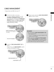
... cable with the PROTECTIVE BRACKET/Screw or the Plug in type Holder. © z It will help prevent the power cable from your TV has the CABLE HOLDER, install it closed. CABLE MANAGEMENT CLIP CABLE HOLDER_ 15 CABLEMANAGEMENT Image shown may differ from being removed by accident. EXTERNAL... is not available for all models.) Or PLUICNTYPhEOLDER.:... _j_iiiiiiiiiiiiiiiiii_iiji_iii'iiiiiiiiiiiiiiiiiiiiiiiiiiiiiiii_iii_i_ii!i!iiiiiiiiiiiiiiiiiiiii_i_ii!!i!ii_ii_i O Install the CABLE MANAGEMENT CLIP as shown, If your TV. O Connect the cables as shown and bundle the cables.
... cable with the PROTECTIVE BRACKET/Screw or the Plug in type Holder. © z It will help prevent the power cable from your TV has the CABLE HOLDER, install it closed. CABLE MANAGEMENT CLIP CABLE HOLDER_ 15 CABLEMANAGEMENT Image shown may differ from being removed by accident. EXTERNAL... is not available for all models.) Or PLUICNTYPhEOLDER.:... _j_iiiiiiiiiiiiiiiiii_iiji_iii'iiiiiiiiiiiiiiiiiiiiiiiiiiiiiiii_iii_i_ii!i!iiiiiiiiiiiiiiiiiiiii_i_ii!!i!ii_ii_i O Install the CABLE MANAGEMENT CLIP as shown, If your TV. O Connect the cables as shown and bundle the cables.

Owners Manual
Page 17
For proper ventilation, allow a clearance of 4 inches on all four sides from your viewing position. 16 PREPARATION DESKTOP PEDESTALINSTALLATION Image shown may differ from the wall. 4 inches 0 z 4 inches 4 inches SWIVELSTAND After installing the TV, you can adjust the TV set manually to the left or right direction by 90 degrees to suit your TV.
For proper ventilation, allow a clearance of 4 inches on all four sides from your viewing position. 16 PREPARATION DESKTOP PEDESTALINSTALLATION Image shown may differ from the wall. 4 inches 0 z 4 inches 4 inches SWIVELSTAND After installing the TV, you can adjust the TV set manually to the left or right direction by 90 degrees to suit your TV.

Owners Manual
Page 18
The TV must be attached to a desk so it cannot be pulled in a forward/backward direction, potentially causing m injury or damaging the product. 7_ Stand 0 z g 4-Screws (not provided as parts of the product) Desk ] -Screw (provided as parts of the product) Stand Desk ]7 ATTACHING THE TV TO A DESK Image shown may differ from your TV.
The TV must be attached to a desk so it cannot be pulled in a forward/backward direction, potentially causing m injury or damaging the product. 7_ Stand 0 z g 4-Screws (not provided as parts of the product) Desk ] -Screw (provided as parts of the product) Stand Desk ]7 ATTACHING THE TV TO A DESK Image shown may differ from your TV.

Owners Manual
Page 19
...or brackets are tightened securely. D"I Image shown may differ from tipping over if pushed backwards. 0 Additionally, we recommend that you set up the TV close to a wall so it cannot be attached to the wall. Secure the wall brackets with the bolts (sold separately) to tie the product...your product has the bolts in the eye-bolts position before inserting the eye-bolts, loosen the bolts. * Insert the eye-bolts or TV brackets/bolts and tighten them securely in a forward direction, z potentially causing injury or damaging the product. Caution: Please make sure that is...
...or brackets are tightened securely. D"I Image shown may differ from tipping over if pushed backwards. 0 Additionally, we recommend that you set up the TV close to a wall so it cannot be attached to the wall. Secure the wall brackets with the bolts (sold separately) to tie the product...your product has the bolts in the eye-bolts position before inserting the eye-bolts, loosen the bolts. * Insert the eye-bolts or TV brackets/bolts and tighten them securely in a forward direction, z potentially causing injury or damaging the product. Caution: Please make sure that is...

Owners Manual
Page 20
... the antenna needs to be split for assistance. 19 ANTENNA OR CABLE CONNECTION 1. If the antenna is not installed properly, contact your dealer for two TV's, install a 2-Way Signal Splitter.
... the antenna needs to be split for assistance. 19 ANTENNA OR CABLE CONNECTION 1. If the antenna is not installed properly, contact your dealer for two TV's, install a 2-Way Signal Splitter.

Owners Manual
Page 21
... (Refer to the COMPONENT IN VIDEO jacks on the remote control. Match the jack colors (Y = green, PB = blue, and PR = red). HD RECEIVERSETUP This TV can receive Digital Over-the-air or Digital Cable signals without an external digital set -top box or other digital external device, refer to the... figure as shown below. How to use Turn on the digital set -top box.) Select Component input source using the INPUT button on the TV. Image shown may differ from a digital set -top box. EXTERNAL EQUIPMENT SETUP To prevent the equipment damage, never plug in any power cords ...
... (Refer to the COMPONENT IN VIDEO jacks on the remote control. Match the jack colors (Y = green, PB = blue, and PR = red). HD RECEIVERSETUP This TV can receive Digital Over-the-air or Digital Cable signals without an external digital set -top box or other digital external device, refer to the... figure as shown below. How to use Turn on the digital set -top box.) Select Component input source using the INPUT button on the TV. Image shown may differ from a digital set -top box. EXTERNAL EQUIPMENT SETUP To prevent the equipment damage, never plug in any power cords ...

Owners Manual
Page 23
How to HDMI Connection 1. set-top box to m z r=== m XD c O Connect the audio output of the digital set-top box to the AUDIO IN (RGB/DVI) jack on the digital set -top box.) Select the HDMI 1 input source on the TV using the INPUT button on the remote control. 22 How to the owner's man- "=O m z -q 2. ual for the digital set -top box. (Refer to use m -q c Turn on the TV. EXTERNALEQUIPMENT SETUP DVI to connect m x -q O theonnHeDcMt I/DthVel DVI IoNutp1utjacokf othnethdeigiTtaVl.
How to HDMI Connection 1. set-top box to m z r=== m XD c O Connect the audio output of the digital set-top box to the AUDIO IN (RGB/DVI) jack on the digital set -top box.) Select the HDMI 1 input source on the TV using the INPUT button on the remote control. 22 How to the owner's man- "=O m z -q 2. ual for the digital set -top box. (Refer to use m -q c Turn on the TV. EXTERNALEQUIPMENT SETUP DVI to connect m x -q O theonnHeDcMt I/DthVel DVI IoNutp1utjacokf othnethdeigiTtaVl.

Owners Manual
Page 24
... player 23 m x -q Match the jack colors (Y = green, PB = blue, and PR = red). Component ports on the TV Video output ports on theTV. Select the Component input source on the TV using the INPUT button on the TV. Connect the video outputs (Y, PB, PR) of the DVD to the COMPONENT IN VIDEO jacks on...
... player 23 m x -q Match the jack colors (Y = green, PB = blue, and PR = red). Component ports on the TV Video output ports on theTV. Select the Component input source on the TV using the INPUT button on the TV. Connect the video outputs (Y, PB, PR) of the DVD to the COMPONENT IN VIDEO jacks on...


