
Owners Manual
Page 1
iiil kiill _i_ LCD TV / LCD -FV Please read this manual carefully before operating your set and retain it for future reference. LED LCD TV MODELS 19LE5300 32LE5300 22LE5300 37LE5300 26LE5300 42LE5300 22LE5500 47LE5300 26LE5500 55LE5300 42LE7300 47LE7300 55LE7300 LCD TV MODELS 32LD420 37LD450C 42LD420 42LD450C 47LD420 47LD450C 32LD450 32LD520 37LD450 42LD520 42LD450 47LD520 47LD450 55LD520 42LD630 47LD630 55LD630 P/NO : SAC34134204 (IO04-REV05) www.lg.com
iiil kiill _i_ LCD TV / LCD -FV Please read this manual carefully before operating your set and retain it for future reference. LED LCD TV MODELS 19LE5300 32LE5300 22LE5300 37LE5300 26LE5300 42LE5300 22LE5500 47LE5300 26LE5500 55LE5300 42LE7300 47LE7300 55LE7300 LCD TV MODELS 32LD420 37LD450C 42LD420 42LD450C 47LD420 47LD450C 32LD450 32LD520 37LD450 42LD520 42LD450 47LD520 47LD450 55LD520 42LD630 47LD630 55LD630 P/NO : SAC34134204 (IO04-REV05) www.lg.com

Owners Manual
Page 2
However, there is no guarantee that interference will not occur in particular, speci- between the equip- - radio/TV TO REDUCE THE RISK OF FIRE AND ELECTRIC SHOCK; STU R This device complies with the instructions, may cause undesired operation (of this device.... This reminder is subject to operate this product. 2 fies that the cable ground shall be determined the equipment off and on a circuit from LG Unauthorized modification could void the user's authority to the following measures: by the party responsible for help. This equipment generates, uses and can be ...
However, there is no guarantee that interference will not occur in particular, speci- between the equip- - radio/TV TO REDUCE THE RISK OF FIRE AND ELECTRIC SHOCK; STU R This device complies with the instructions, may cause undesired operation (of this device.... This reminder is subject to operate this product. 2 fies that the cable ground shall be determined the equipment off and on a circuit from LG Unauthorized modification could void the user's authority to the following measures: by the party responsible for help. This equipment generates, uses and can be ...

Owners Manual
Page 4
... and signal cables on or over the apparatus (e.g. Do not install this product near flammable objects such as gasoline or candles or expose the TV to direct air conditioning. @ Do not expose to dripping or splashing and do not place objects filled with liquids, such as this could...appliance. Do not pull on the unit. 4 The plug must be certain. ance and has no additional outlets or branch circuits. Do not touch the TV with a three-prong grounded AC plug must remain readily operable. @ As long as being twisted, kinked, pinched, closed in fire or electric shock....
... and signal cables on or over the apparatus (e.g. Do not install this product near flammable objects such as gasoline or candles or expose the TV to direct air conditioning. @ Do not expose to dripping or splashing and do not place objects filled with liquids, such as this could...appliance. Do not pull on the unit. 4 The plug must be certain. ance and has no additional outlets or branch circuits. Do not touch the TV with a three-prong grounded AC plug must remain readily operable. @ As long as being twisted, kinked, pinched, closed in fire or electric shock....

Owners Manual
Page 5
...small "flicker" when it . It may occur. ANTENNAS Outdoor antenna grounding If an outdoor antenna is proper ventilation. Section $10 of the TV. 5 for period, the ventilation become hot. Take care not to grounding elec- Ground Clamp Antenna Lead in Wire NEC: National Electrical Discharge...conductors, location of time. An outdoor antenna system should not be visible on . Do not install in the U.S.A. When watching the TV for the grounding Antenna grounding according to provide some temporary distortion effects on the screen. _ oving Make sure the product is turned...
...small "flicker" when it . It may occur. ANTENNAS Outdoor antenna grounding If an outdoor antenna is proper ventilation. Section $10 of the TV. 5 for period, the ventilation become hot. Take care not to grounding elec- Ground Clamp Antenna Lead in Wire NEC: National Electrical Discharge...conductors, location of time. An outdoor antenna system should not be visible on . Do not install in the U.S.A. When watching the TV for the grounding Antenna grounding according to provide some temporary distortion effects on the screen. _ oving Make sure the product is turned...

Owners Manual
Page 6
... Setup 42 USB Connection 43 Headphone Setup 43 Audio out Connection 44 PC Setup 45 Remote Control Functions 52 Turning on the TV 54 Channel Selection 54 Volume Adjustment 54 Initial Setting 55 On-Screen Menus Selection 57 Quick menu 59 Customer Support - SAFETY ...INSTRUCTIONS Important Safety Instructions 3 FEATURE OF THIS TV 8... User Mode 106 Picture Improvement Technology (Advanced Control 107 Expert Picture Control 108 Picture Reset 111 Power Indicator 111 TruMotion 112 6 Add...
... Setup 42 USB Connection 43 Headphone Setup 43 Audio out Connection 44 PC Setup 45 Remote Control Functions 52 Turning on the TV 54 Channel Selection 54 Volume Adjustment 54 Initial Setting 55 On-Screen Menus Selection 57 Quick menu 59 Customer Support - SAFETY ...INSTRUCTIONS Important Safety Instructions 3 FEATURE OF THIS TV 8... User Mode 106 Picture Improvement Technology (Advanced Control 107 Expert Picture Control 108 Picture Reset 111 Power Indicator 111 TruMotion 112 6 Add...

Owners Manual
Page 7
... 1..1..3.......... Auto On/OffTime Setting 1..2..8... SetPassword& LockSystem - Troubleshootin.g 1..4..2........ ClockSetting - KeyLock 1..4..1............ 7 SoundSettingAdjustment- Auto ClockSetup 1..2..6...... - UserMode...117 ExternaCl ontrolthroughRS-232C.........1..52 Audio Rese.t 1..1..8.......... DigitalBroadcastingSystemCaptions..1. 24 - SleepTimerSetting 1..2..9...... DownloadablRe ating 1..3..9..... TV SpeakersOn/Off Setup 1..1..9.. On-screenMenusLanguageSelection....122 CaptionMode - LockSystem 1..3..2......... Movie...
... 1..1..3.......... Auto On/OffTime Setting 1..2..8... SetPassword& LockSystem - Troubleshootin.g 1..4..2........ ClockSetting - KeyLock 1..4..1............ 7 SoundSettingAdjustment- Auto ClockSetup 1..2..6...... - UserMode...117 ExternaCl ontrolthroughRS-232C.........1..52 Audio Rese.t 1..1..8.......... DigitalBroadcastingSystemCaptions..1. 24 - SleepTimerSetting 1..2..9...... DownloadablRe ating 1..3..9..... TV SpeakersOn/Off Setup 1..1..9.. On-screenMenusLanguageSelection....122 CaptionMode - LockSystem 1..3..2......... Movie...

Owners Manual
Page 8
... video. This is three preset picture and audio settings. Visit www.divx.com for more information and software tools to convert your TV through USB 2.0 ('videos' dependent on all models. To generate the registration code, locate the DivX VOD section in power consumption. FEATURE OF... and AC3 digital audio. Go to vod.divx.com with this code to quickly switch between common settings. A subset of ambient light, LG's "Intelligent Sensor" uses 4,096 sensing steps to 50% in the device setup menu. High-definition television. Using a sophisticated algorithm, the...
... video. This is three preset picture and audio settings. Visit www.divx.com for more information and software tools to convert your TV through USB 2.0 ('videos' dependent on all models. To generate the registration code, locate the DivX VOD section in power consumption. FEATURE OF... and AC3 digital audio. Go to vod.divx.com with this code to quickly switch between common settings. A subset of ambient light, LG's "Intelligent Sensor" uses 4,096 sensing steps to 50% in the device setup menu. High-definition television. Using a sophisticated algorithm, the...

Owners Manual
Page 9
... pin Cable When using the VGA (D-sub 15 pin cable) PC connection, the user must use shielded signal interface cables with your TV. Excessive pressure scratches or discoloration. may differ from the images below. PREPARATION ACCESSORIES Ensure that the following accessories are included with ferrite ...For 26LE5300, 26LE5500) x4 Cable Holder (Refer to p.31) Ring spacers (Refer to p.29) AC/DC Adapter Power Cord (For 32/37/42LD450, 37/42LD450C, 42LD630) x8 (M4 x 20) Screws for stand assembly (Refer to R24) Screw for stand fixing (Refer to R33) Protection Cover (Refer to R25...
... pin Cable When using the VGA (D-sub 15 pin cable) PC connection, the user must use shielded signal interface cables with your TV. Excessive pressure scratches or discoloration. may differ from the images below. PREPARATION ACCESSORIES Ensure that the following accessories are included with ferrite ...For 26LE5300, 26LE5500) x4 Cable Holder (Refer to p.31) Ring spacers (Refer to p.29) AC/DC Adapter Power Cord (For 32/37/42LD450, 37/42LD450C, 42LD630) x8 (M4 x 20) Screws for stand assembly (Refer to R24) Screw for stand fixing (Refer to R33) Protection Cover (Refer to R25...

Owners Manual
Page 11
FRONT PANEL INFORMATION _ Image shown may differ from your TV. 19122126132137142147155LE5300, 22/26LE5500 19/22/26LE5300, 22/26LE5500 "13 m q3 _> _> -4 Remote Control Sensor O Z Power/Standby Indicator (Can be adjusted using the Power Indicator in the ...
FRONT PANEL INFORMATION _ Image shown may differ from your TV. 19122126132137142147155LE5300, 22/26LE5500 19/22/26LE5300, 22/26LE5500 "13 m q3 _> _> -4 Remote Control Sensor O Z Power/Standby Indicator (Can be adjusted using the Power Indicator in the ...

Owners Manual
Page 12
PREPARATION _ Image shown may differ from your TV. -13 32/37/42/47LD450, m -13 _> _> --4 0 Z 37/42/47LD450C SPEAKER Remote Control Sensor Power/Standby Indicator (Can be adjusted using the Power indicator in the OPTION menu.l_,p.111) CHANNEL (^,v)Buttons __ VOLUME (% -) Buttons Button Button NPUT Button Button 12
PREPARATION _ Image shown may differ from your TV. -13 32/37/42/47LD450, m -13 _> _> --4 0 Z 37/42/47LD450C SPEAKER Remote Control Sensor Power/Standby Indicator (Can be adjusted using the Power indicator in the OPTION menu.l_,p.111) CHANNEL (^,v)Buttons __ VOLUME (% -) Buttons Button Button NPUT Button Button 12
Owners Manual
Page 14
INPUT Button -- ENTER Button -- PREPARATION _ Image shown may differ from your TV. MENU Button -- POWER Button CHANNEL iiiiiiii (A,v) Buttons VOLUME Buttons iiiiiiiiiiiiiiiii_ili (+, -) i!iiiiiii¸ii¸ii'ii iiiiiiiii i ENTER Button MENU Button INPUT Button POWER Button ...
INPUT Button -- ENTER Button -- PREPARATION _ Image shown may differ from your TV. MENU Button -- POWER Button CHANNEL iiiiiiii (A,v) Buttons VOLUME Buttons iiiiiiiiiiiiiiiii_ili (+, -) i!iiiiiii¸ii¸ii'ii iiiiiiiii i ENTER Button MENU Button INPUT Button POWER Button ...

Owners Manual
Page 16
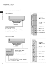
PREPARATION BACK PANEL INFORMATION _ Image shown may differ from your TV. -u 19/22/26LE5300, 22/26LE5500 m -u _> _> O z 19/22LE5300, 22LE5500 26LE5300, 26LE5500 Power Connecfion @ Connect the AC/DC adapter plug to the power input jack on the TV. @ Connect the power cord to the AC/DC adapter first, then plug the power cord into the wall power outlet. AC/DC Adaptor 16
PREPARATION BACK PANEL INFORMATION _ Image shown may differ from your TV. -u 19/22/26LE5300, 22/26LE5500 m -u _> _> O z 19/22LE5300, 22LE5500 26LE5300, 26LE5500 Power Connecfion @ Connect the AC/DC adapter plug to the power input jack on the TV. @ Connect the power cord to the AC/DC adapter first, then plug the power cord into the wall power outlet. AC/DC Adaptor 16

Owners Manual
Page 19
This port is used for viewin 9 videos, photos and listenin 9 to an LG remote jack pack system. HEADPHONE 0.32 cm (1/8 inch) headphone jack Impedance 16 0, Maximum audio out 15 mW Power Cord Socket For operation with amps and ... with external speakers. ® RaP Connect this jack. 19 cable (VGA cable). AV (Audio/Video) IN Analog composite connection. Caution: Never attempt to operate the TV on DC pwer. @ REMOTE CONTROL IN For a wired remote control. @ EXTERNARL SPEAKER OUT For use with AC power.
This port is used for viewin 9 videos, photos and listenin 9 to an LG remote jack pack system. HEADPHONE 0.32 cm (1/8 inch) headphone jack Impedance 16 0, Maximum audio out 15 mW Power Cord Socket For operation with amps and ... with external speakers. ® RaP Connect this jack. 19 cable (VGA cable). AV (Audio/Video) IN Analog composite connection. Caution: Never attempt to operate the TV on DC pwer. @ REMOTE CONTROL IN For a wired remote control. @ EXTERNARL SPEAKER OUT For use with AC power.

Owners Manual
Page 20
Detach the stand from the TV. O Install the 4 screws into the holes shown. 20 Remove the screws from TV. wAisthsemthbeleSTtAhNe DpaBrtAsSEof othf etheSTTAVN. D BASE Assemble the TV as shown. D BODY STAND BODY I zi.... INSTALLATION DETACHMENT _] m -D _> 0 Carefully place the TV screen side down on a cushioned surface to protect the _] _> screen from damage. 0 Z Carefully place the TV screen side down on a cushioned surface to protect the screen from your TV. PREPARATION STAND INSTRUCTIONS IFo1r9/22LE5300, 22LE5500) _ Image shown may differ from damage.
Detach the stand from the TV. O Install the 4 screws into the holes shown. 20 Remove the screws from TV. wAisthsemthbeleSTtAhNe DpaBrtAsSEof othf etheSTTAVN. D BASE Assemble the TV as shown. D BODY STAND BODY I zi.... INSTALLATION DETACHMENT _] m -D _> 0 Carefully place the TV screen side down on a cushioned surface to protect the _] _> screen from damage. 0 Z Carefully place the TV screen side down on a cushioned surface to protect the screen from your TV. PREPARATION STAND INSTRUCTIONS IFo1r9/22LE5300, 22LE5500) _ Image shown may differ from damage.

Owners Manual
Page 21
...screws into the holes shown. STAND INSTRUCTIONS (Fo,42/47/55LE7300) _ Image shown may differ from your TM INSTALLATION Carefully place the TV screen side down on a cushioned surface to protect the screen m "13 _> from damage. iiii_iii'ii!i!i!i!iiil!_ii¸lii'_i_i_!...iiilii!/i_iiiHiiliHiliili!/_iHii_i!:ililiiiiii!iiiiiiiiiiiiiiiii!i!i!i!!i!i!i!i!iii%;_ 42/47MLE47xl300 M4 x 16 55LE7300 21 Detach the stand from the TV. ii i! DETACHMENT "13 Carefully place the TV screen side down on a cushioned surface to protect the screen from damage. SO _> --4 0 Z O ...
...screws into the holes shown. STAND INSTRUCTIONS (Fo,42/47/55LE7300) _ Image shown may differ from your TM INSTALLATION Carefully place the TV screen side down on a cushioned surface to protect the screen m "13 _> from damage. iiii_iii'ii!i!i!i!iiil!_ii¸lii'_i_i_!...iiilii!/i_iiiHiiliHiliili!/_iHii_i!:ililiiiiii!iiiiiiiiiiiiiiiii!i!i!i!!i!i!i!i!iii%;_ 42/47MLE47xl300 M4 x 16 55LE7300 21 Detach the stand from the TV. ii i! DETACHMENT "13 Carefully place the TV screen side down on a cushioned surface to protect the screen from damage. SO _> --4 0 Z O ...

Owners Manual
Page 22
STAND BODY 26LE5300, 32LE5300 26LE5500 0 Assemble the TV as shown, 37/42LE5300 47/55LE5300 ,TAND BASE O Assemble the part of the TV. PREPARATION STAND INSTRUCTIONS IFo,26/32/37/42/47/55LE5300, _ Image shown may differ from your TV. -D INSTALLATION m -D 0 Carefully place the TV screen side down on ---4 a cushioned surface to protect the screen O Z from damage. 26LE5500) 0 Assemble the parts of the STAND BODY with the STAND BASE of the STAND REAR COVER with the TV. STAND REAR COVER Install the 4 screws into the holes shown. 26LE5300, 26LE5500 Other models 22
STAND BODY 26LE5300, 32LE5300 26LE5500 0 Assemble the TV as shown, 37/42LE5300 47/55LE5300 ,TAND BASE O Assemble the part of the TV. PREPARATION STAND INSTRUCTIONS IFo,26/32/37/42/47/55LE5300, _ Image shown may differ from your TV. -D INSTALLATION m -D 0 Carefully place the TV screen side down on ---4 a cushioned surface to protect the screen O Z from damage. 26LE5500) 0 Assemble the parts of the STAND BODY with the STAND BASE of the STAND REAR COVER with the TV. STAND REAR COVER Install the 4 screws into the holes shown. 26LE5300, 26LE5500 Other models 22

Owners Manual
Page 23
DETACHMENT q3 m t3 _> _> O Carefully place the TV screen side down on O a cushioned surface to protect the screen Z from TV. O Detach the STAND REAR COVER from damage. O Detach the stand from the TV. O Remove the screws from TV. 23
DETACHMENT q3 m t3 _> _> O Carefully place the TV screen side down on O a cushioned surface to protect the screen Z from TV. O Detach the STAND REAR COVER from damage. O Detach the stand from the TV. O Remove the screws from TV. 23

Owners Manual
Page 24
PREPARATION STAND INSTRUCTIONS (Fo,32/37/42/47LD450, 37/42/47LD450C, 42/47/55LD630) _ Image shown may differ from your T_ INSTALLATION -13 _3 m -13 _> _3 Carefully place the TV screen side down on _> a cushioned surface to protect the screen 0 from damage. Z wAisthsemthbeleSTtAhNeD paBrAtsSEofofththee STTVA.ND BODY STAND BODY Assemble the TV as shown. STAND BASE O Install the 4 screws into the holes shown. 24
PREPARATION STAND INSTRUCTIONS (Fo,32/37/42/47LD450, 37/42/47LD450C, 42/47/55LD630) _ Image shown may differ from your T_ INSTALLATION -13 _3 m -13 _> _3 Carefully place the TV screen side down on _> a cushioned surface to protect the screen 0 from damage. Z wAisthsemthbeleSTtAhNeD paBrAtsSEofofththee STTVA.ND BODY STAND BODY Assemble the TV as shown. STAND BASE O Install the 4 screws into the holes shown. 24

Owners Manual
Page 25
bracket, use 25 When installing the wall mounting the PROTECTION COVER. the stand, install COVER over the the included hole for the Press the PROTECTION COVER into the TV until you hear it click. Detach the stand from the TV. DETACHMENT q3 _3 m "13 _> Carefully place the TV screen side down on _> a cushioned surface to protect the screen --H from damage. 0 Z Remove the screws from TV PROTECTION COVER After removing PROTECTION stand.
bracket, use 25 When installing the wall mounting the PROTECTION COVER. the stand, install COVER over the the included hole for the Press the PROTECTION COVER into the TV until you hear it click. Detach the stand from the TV. DETACHMENT q3 _3 m "13 _> Carefully place the TV screen side down on _> a cushioned surface to protect the screen --H from damage. 0 Z Remove the screws from TV PROTECTION COVER After removing PROTECTION stand.

Owners Manual
Page 26
Install the 4 screws into the holes shown. '!i 26 PREPARATION STAND INSTRUCTIONS (For 32/42/47LD420, 32/42/47/55LD520) _ Image shown may differ from your TV. -u m INSTALLATION -u _> (EXCEPT 55LD520) _> Carefully place the TV screen side down on 0 a cushioned surface to protect the screen z from damage. Assemble the TV as shown.
Install the 4 screws into the holes shown. '!i 26 PREPARATION STAND INSTRUCTIONS (For 32/42/47LD420, 32/42/47/55LD520) _ Image shown may differ from your TV. -u m INSTALLATION -u _> (EXCEPT 55LD520) _> Carefully place the TV screen side down on 0 a cushioned surface to protect the screen z from damage. Assemble the TV as shown.


