
Owner's Manual (English)
Page 1
See the label attached on the back cover and quote t tion to your set . www.lgcommercial.com LCD TV PLASMA TV OWNER'S MANUAL LCD TV MODELS PLASMA TV MODEL 32LC5DC 32LC50C 42PX8DC 32LC5DCS 32LC50CS 32LC5DCB 32LC50CB 37LC5DC 32LX50C 37LC5DCB 32LX50CS 37LC5DC1 37LC50C 42LC5DC 37LC50CB 32LX5DC 42LB50C 32LX5DCS 42LC50C 42LB5DC Please read this manual carefully before operating your dealer when you require service. Retain it for future reference. Record model number and serial number of the set .
See the label attached on the back cover and quote t tion to your set . www.lgcommercial.com LCD TV PLASMA TV OWNER'S MANUAL LCD TV MODELS PLASMA TV MODEL 32LC5DC 32LC50C 42PX8DC 32LC5DCS 32LC50CS 32LC5DCB 32LC50CB 37LC5DC 32LX50C 37LC5DCB 32LX50CS 37LC5DC1 37LC50C 42LC5DC 37LC50CB 32LX5DC 42LB50C 32LX5DCS 42LC50C 42LB5DC Please read this manual carefully before operating your dealer when you require service. Retain it for future reference. Record model number and serial number of the set .
Owner's Manual (English)
Page 3
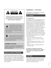
... there is intended to alert the user to an outlet on , the user is connected. - Consult the dealer or an experienced radio/TV technician for proper grounding and, in particular, specifies that interference will not occur in the literature accompanying the appliance. Any changes or modifications not...to the presence of the cable entry as close to correct the interference by turning the equipment off and on a circuit different from LG Electronics. This equipment generates, uses and can be determined by one or more of electric shock to radio communications. If this product...
... there is intended to alert the user to an outlet on , the user is connected. - Consult the dealer or an experienced radio/TV technician for proper grounding and, in particular, specifies that interference will not occur in the literature accompanying the appliance. Any changes or modifications not...to the presence of the cable entry as close to correct the interference by turning the equipment off and on a circuit different from LG Electronics. This equipment generates, uses and can be determined by one or more of electric shock to radio communications. If this product...
Owner's Manual (English)
Page 6
... 63 Caption Options 64 EZ Picture - Picture Improvement Technology 49 Advanced - Analog Broadcasting System Captions 62 - Add / Delete Channel (Manual Scan 37 - Preset 46 Manual Picture Adjustment - Black (Darkness) Level 51 Picture Reset 52 Low-Power Picture Mode 52 Image Sticking Minimization( ISM) Method... 7 Front Panel Controls 8 Back Panel Information 11 Back Cover for Wire Arrangement 13 Attaching the TV to a Wall 16 Swivel Stand 16 Attaching the TV to a Desk 17 Stand Installation 18 VESA Wall Mounting 19 Desktop Pedestal Installation 19 Antenna or Cable...
... 63 Caption Options 64 EZ Picture - Picture Improvement Technology 49 Advanced - Analog Broadcasting System Captions 62 - Add / Delete Channel (Manual Scan 37 - Preset 46 Manual Picture Adjustment - Black (Darkness) Level 51 Picture Reset 52 Low-Power Picture Mode 52 Image Sticking Minimization( ISM) Method... 7 Front Panel Controls 8 Back Panel Information 11 Back Cover for Wire Arrangement 13 Attaching the TV to a Wall 16 Swivel Stand 16 Attaching the TV to a Desk 17 Stand Installation 18 VESA Wall Mounting 19 Desktop Pedestal Installation 19 Antenna or Cable...
Owner's Manual (English)
Page 7
... Rating (MPAA) 77 Downloadable Rating 77 - Setting up Your Password 74 Set Password 75 Lock System 75 Channel Blocking 76 External Input Blocking 76 Movie & TV Rating 77 - TIME SETTING Clock Setting 65 Auto Clock Setup 65 Manual Clock Setup 66 Auto On/Off Timer Setting 67 Auto Shut-off Setting...
... Rating (MPAA) 77 Downloadable Rating 77 - Setting up Your Password 74 Set Password 75 Lock System 75 Channel Blocking 76 External Input Blocking 76 Movie & TV Rating 77 - TIME SETTING Clock Setting 65 Auto Clock Setup 65 Manual Clock Setup 66 Auto On/Off Timer Setting 67 Auto Shut-off Setting...

Owner's Manual (English)
Page 8
...lamp and or a series of fluorescent lamps. The Picture-in-Picture feature allows you get perfect images that are easily viewable. FOR LCD TV If the TV feels cold to the touch, there may produce some temporary distortion effects on the screen, appearing as pixels, which are the same...sub-pixel to produce colored light (red, green, or blue). Avoid touching the LCD screen or holding your plasma display to a PC and use it is used in other Plasma TV manufacturers' products. Plasma TV is individually controlled by advanced electronics to produce over 160 degrees. b. Do not ...
...lamp and or a series of fluorescent lamps. The Picture-in-Picture feature allows you get perfect images that are easily viewable. FOR LCD TV If the TV feels cold to the touch, there may produce some temporary distortion effects on the screen, appearing as pixels, which are the same...sub-pixel to produce colored light (red, green, or blue). Avoid touching the LCD screen or holding your plasma display to a PC and use it is used in other Plasma TV manufacturers' products. Plasma TV is individually controlled by advanced electronics to produce over 160 degrees. b. Do not ...

Owner's Manual (English)
Page 9
...twist holder. 32/37/42LC5DC*, 32/37/42LC50C*, 42LB5DC, 42LB50C models only D-sub 15 pin Cable x 2 Cable Management (Refer to p.13) Cable Holder (Refer to p.13) 1-Bolt for fixing the 4-Bolts for stand Cable Holder assembly (Refer to p.13) (Refer to p.18) 32/37LC5DC*, 32/37LC50C* models...Slightly wipe stained spot on surface of that the following accessories are included with your product. LCD TV PLASMA TV Owner's Manual http://www.lgusa.com www.lg.ca Copyright© 2007 LGE, All Rights Reserved. TV Bracket Bolts 2- PIP CH SWAP + DVD VCR PIP INPUT INFO EXIT CC MENU RATIO...
...twist holder. 32/37/42LC5DC*, 32/37/42LC50C*, 42LB5DC, 42LB50C models only D-sub 15 pin Cable x 2 Cable Management (Refer to p.13) Cable Holder (Refer to p.13) 1-Bolt for fixing the 4-Bolts for stand Cable Holder assembly (Refer to p.13) (Refer to p.18) 32/37LC5DC*, 32/37LC50C* models...Slightly wipe stained spot on surface of that the following accessories are included with your product. LCD TV PLASMA TV Owner's Manual http://www.lgusa.com www.lg.ca Copyright© 2007 LGE, All Rights Reserved. TV Bracket Bolts 2- PIP CH SWAP + DVD VCR PIP INPUT INFO EXIT CC MENU RATIO...
Owner's Manual (English)
Page 10
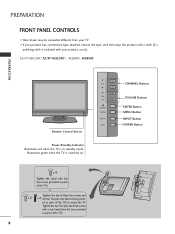
... screws (provided as parts of the TV). Illuminates green when the TV is in standby mode. PREPARATION FRONT PANEL CONTROLS ■ Here shown may be somewhat different from your TV. ■ If your product, use it). 32/37/42LC5DC*,32/37/42LC50C*, 42LB5DC, 42LB50C PREPARATION Remote Control... Sensor Power/Standby Indicator Illuminates red when the TV is switched on. CH VOL ENTER MENU INPUT CHANNEL Buttons ...
... screws (provided as parts of the TV). Illuminates green when the TV is in standby mode. PREPARATION FRONT PANEL CONTROLS ■ Here shown may be somewhat different from your TV. ■ If your product, use it). 32/37/42LC5DC*,32/37/42LC50C*, 42LB5DC, 42LB50C PREPARATION Remote Control... Sensor Power/Standby Indicator Illuminates red when the TV is switched on. CH VOL ENTER MENU INPUT CHANNEL Buttons ...

Owner's Manual (English)
Page 11
CH VOL ENTER MENU INPUT ON/OFF ON/OFF Button INPUT Button MENU Button ENTER Button VOLUME Buttons CHANNEL Buttons 9 Illuminates green when the TV is in standby mode. PREPARATION 32LX5DC*, 32LX50C* Remote Control Sensor Power/Standby Indicator Illuminates red when the TV is switched on.
CH VOL ENTER MENU INPUT ON/OFF ON/OFF Button INPUT Button MENU Button ENTER Button VOLUME Buttons CHANNEL Buttons 9 Illuminates green when the TV is in standby mode. PREPARATION 32LX5DC*, 32LX50C* Remote Control Sensor Power/Standby Indicator Illuminates red when the TV is switched on.

Owner's Manual (English)
Page 12
PREPARATION 42PX8DC PREPARATION INPUT ENTER This TV's stand is switched on. 10 INPUT ENTER Illuminates green when the TV is sold, separately. INPUT MENU ENTER VOL CH POWER Button INPUT Button MENU Button ENTER Button VOLUME Buttons CHANNEL Buttons Remote Control Sensor Power/Standby Indicator Illuminates red when the TV is in standby mode.
PREPARATION 42PX8DC PREPARATION INPUT ENTER This TV's stand is switched on. 10 INPUT ENTER Illuminates green when the TV is sold, separately. INPUT MENU ENTER VOL CH POWER Button INPUT Button MENU Button ENTER Button VOLUME Buttons CHANNEL Buttons Remote Control Sensor Power/Standby Indicator Illuminates red when the TV is in standby mode.
Owner's Manual (English)
Page 13
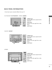
AUDIO Input 11 11 VIDEO L/MONO AUDIO R VIDEO Input Connects the video signal from your TV. 32/37/42LC5DC*,32/37/42LC50C*, 42LB5DC, 42LB50C S-VIDEO S-VIDEO Input Provides better picture quality than the video input. PREPARATION BACK PANEL INFORMATION ■ Here shown may be somewhat different ...
AUDIO Input 11 11 VIDEO L/MONO AUDIO R VIDEO Input Connects the video signal from your TV. 32/37/42LC5DC*,32/37/42LC50C*, 42LB5DC, 42LB50C S-VIDEO S-VIDEO Input Provides better picture quality than the video input. PREPARATION BACK PANEL INFORMATION ■ Here shown may be somewhat different ...

Owner's Manual (English)
Page 14
... to these jacks. 10 RJP INTERFACE 11 Power Cord Socket For operation with AC power. This part mainly use picture for the LCD TV models. S-VIDEO Connect S-Video out from your TV. AUDIO IN (RGB, DVI) Connect the audio from a PC or DTV. 7 SPEAKER OUT 8Ω 8 AV (Audio/Video) IN 1 Connect ...audio/video output from a PC. Caution: Never attempt to operate the TV on DC power. 12 ANTENNA IN Connect over-the air signals to these ports do not work. 3 13 M.P.I . 4 RESET 5 SERVICE ONLY REMOTE CONTROL UPDATE OUT...
... to these jacks. 10 RJP INTERFACE 11 Power Cord Socket For operation with AC power. This part mainly use picture for the LCD TV models. S-VIDEO Connect S-Video out from your TV. AUDIO IN (RGB, DVI) Connect the audio from a PC or DTV. 7 SPEAKER OUT 8Ω 8 AV (Audio/Video) IN 1 Connect ...audio/video output from a PC. Caution: Never attempt to operate the TV on DC power. 12 ANTENNA IN Connect over-the air signals to these ports do not work. 3 13 M.P.I . 4 RESET 5 SERVICE ONLY REMOTE CONTROL UPDATE OUT...
Owner's Manual (English)
Page 15
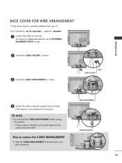
... CABLE MANAGEMENT with both hands and pull it backward. PREPARATION BACK COVER FOR WIRE ARRANGEMENT ■ Here shown may be somewhat different from your TV. 32/37/42LC5DC*,32/37/42LC50C*, 42LB5DC, 42LB50C 1 Connect the cables as shown. To connect an additional equipment, see the EXTERNAL EQUIPMENT SETUP section. 2 Install the CABLE HOLDER...
... CABLE MANAGEMENT with both hands and pull it backward. PREPARATION BACK COVER FOR WIRE ARRANGEMENT ■ Here shown may be somewhat different from your TV. 32/37/42LC5DC*,32/37/42LC50C*, 42LB5DC, 42LB50C 1 Connect the cables as shown. To connect an additional equipment, see the EXTERNAL EQUIPMENT SETUP section. 2 Install the CABLE HOLDER...
Owner's Manual (English)
Page 16
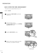
PREPARATION 2 Connect the cables as shown. 4 Bundle the cables using the supplied twister holder. (This feature is not available for all models.) 14 BOLT CABLE HOLDER TWISTER HOLDER To connect an additional equipment, see the EXTERNAL EQUIPMENT SETUP section. 3 Install the CABLE HOLDER as necessary. PREPARATION BACK COVER FOR WIRE ARRANGEMENT ■ Here shown may be somewhat different from your TV. 32LX5DC*, 32LX50C* 1 To separate the CABLE HOLDER, loosen the bolt installed the set.
PREPARATION 2 Connect the cables as shown. 4 Bundle the cables using the supplied twister holder. (This feature is not available for all models.) 14 BOLT CABLE HOLDER TWISTER HOLDER To connect an additional equipment, see the EXTERNAL EQUIPMENT SETUP section. 3 Install the CABLE HOLDER as necessary. PREPARATION BACK COVER FOR WIRE ARRANGEMENT ■ Here shown may be somewhat different from your TV. 32LX5DC*, 32LX50C* 1 To separate the CABLE HOLDER, loosen the bolt installed the set.
Owner's Manual (English)
Page 18
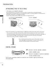
...SWIVEL STAND 20° (37LC5DC1, 42LC5DC, 42LC50C, 42PX8DC, 42LB5DC, 42LB50C models) 90° (32LX5DC/S, 32LX50C/S, 32LC5DC/S, 32LC50C/S, 37LC5DC, 37LC50C models) The TV can be pulled in a forward direction, potentially causing injury or damaging the product. Match the height of the product, must purchase ...separately) on or hang from the TV. 32/37/42LC5DC*,32/37/42LC50C*, 42LB5DC, 42LB50C 32LX5DC*, 32LX50C* PREPARATION ■ Insert the TV brackets (or eye-bolts) and bolts to tighten the product to the wall as ...
...SWIVEL STAND 20° (37LC5DC1, 42LC5DC, 42LC50C, 42PX8DC, 42LB5DC, 42LB50C models) 90° (32LX5DC/S, 32LX50C/S, 32LC5DC/S, 32LC50C/S, 37LC5DC, 37LC50C models) The TV can be pulled in a forward direction, potentially causing injury or damaging the product. Match the height of the product, must purchase ...separately) on or hang from the TV. 32/37/42LC5DC*,32/37/42LC50C*, 42LB5DC, 42LB50C 32LX5DC*, 32LX50C* PREPARATION ■ Insert the TV brackets (or eye-bolts) and bolts to tighten the product to the wall as ...
Owner's Manual (English)
Page 19
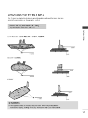
M5 x 25 32/37/42LC5DC*, 32/37/42LC50C*, 42LB5DC, 42LB50C 32LX5DC*, 32LX50C* 4-Screws Stand Desk 42PX8DC 4-Screws Stand Desk Stand 2-Screws Desk WARNING G This apparatus must be pulled in a forward/backward direction, potentially causing injury or damaging the product. * Screws - PREPARATION ATTACHING THE TV TO A DESK The TV must be securely attached to desk so it cannot be attached to the floor/wall per installation instructions.Tipping, shaking, or rocking the machine may cause injury/death. 17 M5 x L (table depth + 8~10 mm) ex) table depth-15mm: Bolts -
M5 x 25 32/37/42LC5DC*, 32/37/42LC50C*, 42LB5DC, 42LB50C 32LX5DC*, 32LX50C* 4-Screws Stand Desk 42PX8DC 4-Screws Stand Desk Stand 2-Screws Desk WARNING G This apparatus must be pulled in a forward/backward direction, potentially causing injury or damaging the product. * Screws - PREPARATION ATTACHING THE TV TO A DESK The TV must be securely attached to desk so it cannot be attached to the floor/wall per installation instructions.Tipping, shaking, or rocking the machine may cause injury/death. 17 M5 x L (table depth + 8~10 mm) ex) table depth-15mm: Bolts -
Owner's Manual (English)
Page 22
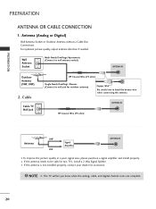
... a Cable Box Connections. Wall Antenna Socket Multi-family Dwellings/Apartments (Connect to wall antenna socket) ANTENNA IN M.P.I . Cable Cable TV Wall Jack RF Coaxial Wire (75 ohm) Single-family Dwellings /Houses (Connect to bend the bronze wire when connecting the antenna. NOTE G The...picture quality in a poor signal area, please purchase a signal amplifier and install properly. ■ If the antenna needs to be split for two TV's, install a 2-Way Signal Splitter. ■ If the antenna is not installed properly, contact your dealer for outdoor antenna) Copper Wire Be careful...
... a Cable Box Connections. Wall Antenna Socket Multi-family Dwellings/Apartments (Connect to wall antenna socket) ANTENNA IN M.P.I . Cable Cable TV Wall Jack RF Coaxial Wire (75 ohm) Single-family Dwellings /Houses (Connect to bend the bronze wire when connecting the antenna. NOTE G The...picture quality in a poor signal area, please purchase a signal amplifier and install properly. ■ If the antenna needs to be split for two TV's, install a 2-Way Signal Splitter. ■ If the antenna is not installed properly, contact your dealer for outdoor antenna) Copper Wire Be careful...

Owner's Manual (English)
Page 23
... (Y, PB, PR) of external equipment setup mainly use ■ Turn on the digital set-top box. (Refer to the owner's manual for LCD TV models. HD RECEIVER SETUP This TV can receive Digital Over-the-air/Cable signals without an external digital set . 2. When connecting Component cable 1. How to use picture for the...
... (Y, PB, PR) of external equipment setup mainly use ■ Turn on the digital set-top box. (Refer to the owner's manual for LCD TV models. HD RECEIVER SETUP This TV can receive Digital Over-the-air/Cable signals without an external digital set . 2. When connecting Component cable 1. How to use picture for the...

Owner's Manual (English)
Page 26
...). EXTERNAL EQUIPMENT SETUP EXTERNAL EQUIPMENT SETUP DVD SETUP When connecting Component cable 1. How to the component input ports as shown below. Component ports on the TV Y Y Video output ports Y on the set . 2. HDMI/DVI IN 1(DVI) 1 2 DIGITAL AUDIO OUT (OPTICAL) 2 M.P.I. ■ Select Component input source with using the INPUT button on...
...). EXTERNAL EQUIPMENT SETUP EXTERNAL EQUIPMENT SETUP DVD SETUP When connecting Component cable 1. How to the component input ports as shown below. Component ports on the TV Y Y Video output ports Y on the set . 2. HDMI/DVI IN 1(DVI) 1 2 DIGITAL AUDIO OUT (OPTICAL) 2 M.P.I. ■ Select Component input source with using the INPUT button on...
Owner's Manual (English)
Page 28
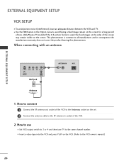
... R ANT OUT OUTPUT SWITCH ANT IN Wall Jack 2 Antenna ANTENNA IN M.P.I. 1. How to use ■ Set VCR output switch to 3 or 4 and then tune TV to the same channel number. ■ Insert a video tape into the VCR and press PLAY on the VCR. (Refer to all manufactures and in consequence...'s manual.) 26 EXTERNAL EQUIPMENT SETUP EXTERNAL EQUIPMENT SETUP VCR SETUP ■ To avoid picture noise (interference), leave an adequate distance between the VCR and TV. ■ Use the ISM feature in the Option menu to avoid having a fixed image remain on the screen for a long period of the screen...
... R ANT OUT OUTPUT SWITCH ANT IN Wall Jack 2 Antenna ANTENNA IN M.P.I. 1. How to use ■ Set VCR output switch to 3 or 4 and then tune TV to the same channel number. ■ Insert a video tape into the VCR and press PLAY on the VCR. (Refer to all manufactures and in consequence...'s manual.) 26 EXTERNAL EQUIPMENT SETUP EXTERNAL EQUIPMENT SETUP VCR SETUP ■ To avoid picture noise (interference), leave an adequate distance between the VCR and TV. ■ Use the ISM feature in the Option menu to avoid having a fixed image remain on the screen for a long period of the screen...
Owner's Manual (English)
Page 29
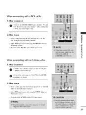
..., select A V 2 input source. AUDIO ENT IN S-VIDEO (MONO) AUDIO AV IN 1 VIDEO SPEAK OUT 8 ■ If connected to connect 1 Connect the AUDIO/VIDEO jacks between TV and VCR. ANT IN S-VIDEO L R VIDEO ANT OUT OUTPUT SWITCH 2 Connect the audio outputs of the VCR to the S -VIDEO input on the VCR. (Refer...
..., select A V 2 input source. AUDIO ENT IN S-VIDEO (MONO) AUDIO AV IN 1 VIDEO SPEAK OUT 8 ■ If connected to connect 1 Connect the AUDIO/VIDEO jacks between TV and VCR. ANT IN S-VIDEO L R VIDEO ANT OUT OUTPUT SWITCH 2 Connect the audio outputs of the VCR to the S -VIDEO input on the VCR. (Refer...


