
User Manual
Page 1
See the label attached on the back cover and quote this manual carefully before operating your dealer when you require service. www.lgcommercial.com Retain it for future reference. Record model number and serial number of the set . LCD TV PLASMA TV OWNER'S MANUAL LCD TV MODELS PLASMA TV MODEL 32LC5DC 32LC50C 42PX8DC 32LC5DCS 32LC50CS 42PG65C 32LC5DCB 32LC50CB 42PG60C 37LC5DC 32LX50C 37LC5DCB 32LX50CS 37LC5DC1 37LC50C 42LC5DC 37LC50CB 32LX5DC 42LB50C 32LX5DCS 42LC50C 42LB5DC Please read this information to your set .
See the label attached on the back cover and quote this manual carefully before operating your dealer when you require service. www.lgcommercial.com Retain it for future reference. Record model number and serial number of the set . LCD TV PLASMA TV OWNER'S MANUAL LCD TV MODELS PLASMA TV MODEL 32LC5DC 32LC50C 42PX8DC 32LC5DCS 32LC50CS 42PG65C 32LC5DCB 32LC50CB 42PG60C 37LC5DC 32LX50C 37LC5DCB 32LX50CS 37LC5DC1 37LC50C 42LC5DC 37LC50CB 32LX5DC 42LB50C 32LX5DCS 42LC50C 42LB5DC Please read this information to your set .
User Manual
Page 3
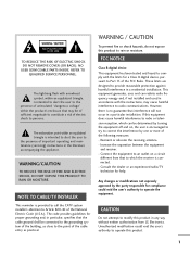
... the National Electric Code (U.S.A.). Increase the separation between the equipment and receiver. - Consult the dealer or an experienced radio/TV technician for compliance could void the user's authority to provide reasonable protection against harmful interference in any way without written authorization... PARTS INSIDE. This equipment generates, uses and can be determined by turning the equipment off and on a circuit different from LG Electronics. If this equipment does cause harmful interference to radio or television reception, which can radiate radio frequency energy and, if...
... the National Electric Code (U.S.A.). Increase the separation between the equipment and receiver. - Consult the dealer or an experienced radio/TV technician for compliance could void the user's authority to provide reasonable protection against harmful interference in any way without written authorization... PARTS INSIDE. This equipment generates, uses and can be determined by turning the equipment off and on a circuit different from LG Electronics. If this equipment does cause harmful interference to radio or television reception, which can radiate radio frequency energy and, if...

User Manual
Page 5
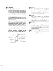
.... The plug must be placed upon . Do not connect too many appliances to a three-prong grouned AC outlet) If grounding methods are dangerous. a TV with a three-prong grounded AC plug must remain readily operable. 19 Keep the product away from physical or mechanical abuse, such as this could result... direct sunlight. 3 Any of fire or electrical shock, do not place objects filled with liquids, such as gasoline or candles or expose the TV to direct air conditioning. 16 Do not expose to be certain. Do not overload wall outlets. that appliance and has no additional outlets or ...
.... The plug must be placed upon . Do not connect too many appliances to a three-prong grouned AC outlet) If grounding methods are dangerous. a TV with a three-prong grounded AC plug must remain readily operable. 19 Keep the product away from physical or mechanical abuse, such as this could result... direct sunlight. 3 Any of fire or electrical shock, do not place objects filled with liquids, such as gasoline or candles or expose the TV to direct air conditioning. 16 Do not expose to be certain. Do not overload wall outlets. that appliance and has no additional outlets or ...
User Manual
Page 6
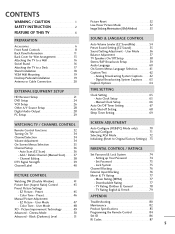
... precautions below. Do not clean with cloth or other liquids directly on the front panel of overhead power lines or other odors coming from the TV or hear strange sounds, unplug the power cord contact an authorized service center. 4 It may occur. Do not install in a confined space such as to... provide some protection against or put stress on the TV as death or serious injury can come in excessively dusty places. 24 If you smell smoke or other electric light or power circuits, or where...
... precautions below. Do not clean with cloth or other liquids directly on the front panel of overhead power lines or other odors coming from the TV or hear strange sounds, unplug the power cord contact an authorized service center. 4 It may occur. Do not install in a confined space such as to... provide some protection against or put stress on the TV as death or serious injury can come in excessively dusty places. 24 If you smell smoke or other electric light or power circuits, or where...
User Manual
Page 7
... Audio Language 60 On-Screen Menus Language Selection 61 Caption/Text 62 - Movie Rating (MPAA) 77 Downloadable Rating 77 TV Rating Children & General 78 TV Rating English & French 79 APPENDIX Troubleshooting 80 Maintenance 82 Product Specifications 83 Programming the Remote Control 84 Set ID 86 ... (EZ Scan 36 - Setting up Your Password 74 Set Password 75 Lock System 75 Channel Blocking 76 External Input Blocking 76 Movie & TV Rating 77 - Preset 45 - Channel Editing 38 DTV Signal Strength 39 Channel Label 40 PICTURE CONTROL Watching DW (Double Window 41 Picture ...
... Audio Language 60 On-Screen Menus Language Selection 61 Caption/Text 62 - Movie Rating (MPAA) 77 Downloadable Rating 77 TV Rating Children & General 78 TV Rating English & French 79 APPENDIX Troubleshooting 80 Maintenance 82 Product Specifications 83 Programming the Remote Control 84 Set ID 86 ... (EZ Scan 36 - Setting up Your Password 74 Set Password 75 Lock System 75 Channel Blocking 76 External Input Blocking 76 Movie & TV Rating 77 - Preset 45 - Channel Editing 38 DTV Signal Strength 39 Channel Label 40 PICTURE CONTROL Watching DW (Double Window 41 Picture ...
User Manual
Page 8
... Slightly wipe stained spot on the screen. c. User must be cautions of mercury. LCD TV PLASMA TV Owner's Manual http://www.lgusa.com www.lg.ca Copyright© 2007 LGE, All Rights Reserved. TV UT INPUT MULTI POWER TMVODE VOL EZRPAICTPSIIOPTEBTZ SVOPUIPNDCH -SPWPOAIPPWCHE+ RPIP DVD VCR INPUDT VD CC ... feature is not available Please be carried out in this product contains a small amount of that the following accessories are included with TV. However, they have no adverse effect on surface of this product must use shielded signal interface cables (D-sub 15 pin cable) with...
... Slightly wipe stained spot on the screen. c. User must be cautions of mercury. LCD TV PLASMA TV Owner's Manual http://www.lgusa.com www.lg.ca Copyright© 2007 LGE, All Rights Reserved. TV UT INPUT MULTI POWER TMVODE VOL EZRPAICTPSIIOPTEBTZ SVOPUIPNDCH -SPWPOAIPPWCHE+ RPIP DVD VCR INPUDT VD CC ... feature is not available Please be carried out in this product contains a small amount of that the following accessories are included with TV. However, they have no adverse effect on surface of this product must use shielded signal interface cables (D-sub 15 pin cable) with...

User Manual
Page 9
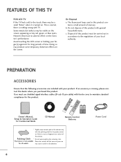
PREPARATION LCD TV model only Option Extras Protective Bracket and Bolt for Power Cord (This feature is not available for all models.) (Refer to P.13) D-sub 15 pin ... (Refer to p.13) 4-Bolts for stand assembly (Refer to p.18) Only 32/37LC5DC*, 32/37LC50C* models x 2 M4xL22 Torx plus Star head screw (Refer to p.8) Plasma TV models only 75 ohm Round Cable D-sub 15 Pin Cable (Except 42PG60C/65C) (Except 42PG60C/65C) Cable Holder (Except 42PX8DC) Only 42PG65C model x 4 Cable Management...
PREPARATION LCD TV model only Option Extras Protective Bracket and Bolt for Power Cord (This feature is not available for all models.) (Refer to P.13) D-sub 15 pin ... (Refer to p.13) 4-Bolts for stand assembly (Refer to p.18) Only 32/37LC5DC*, 32/37LC50C* models x 2 M4xL22 Torx plus Star head screw (Refer to p.8) Plasma TV models only 75 ohm Round Cable D-sub 15 Pin Cable (Except 42PG60C/65C) (Except 42PG60C/65C) Cable Holder (Except 42PX8DC) Only 42PG65C model x 4 Cable Management...

User Manual
Page 10
...; If your product, use it). 32/37/42LC5DC*,32/37/42LC50C*, 42LB5DC, 42LB50C PREPARATION Remote Control Sensor Power/Standby Indicator Illuminates red when the TV is switched on. Tighten the two Torx plus star head screws (provid- or Tighten the two of these four screws and x 2 x 2 the two Torx ...plus star head screws with a star head driver bit (not provided as parts of the TV) to secure the TV. ed as parts of the TV). CH VOL ENTER MENU INPUT CHANNEL Buttons VOLUME Buttons ENTER Button MENU Button INPUT Button POWER Button x 4 Tighten the stand with...
...; If your product, use it). 32/37/42LC5DC*,32/37/42LC50C*, 42LB5DC, 42LB50C PREPARATION Remote Control Sensor Power/Standby Indicator Illuminates red when the TV is switched on. Tighten the two Torx plus star head screws (provid- or Tighten the two of these four screws and x 2 x 2 the two Torx ...plus star head screws with a star head driver bit (not provided as parts of the TV) to secure the TV. ed as parts of the TV). CH VOL ENTER MENU INPUT CHANNEL Buttons VOLUME Buttons ENTER Button MENU Button INPUT Button POWER Button x 4 Tighten the stand with...

User Manual
Page 11
PREPARATION 32LX5DC*, 32LX50C* Remote Control Sensor Power/Standby Indicator Illuminates red when the TV is switched on. CH VOL ENTER MENU INPUT ON/OFF ON/OFF Button INPUT Button MENU Button ENTER Button VOLUME Buttons CHANNEL Buttons 9 Illuminates green when the TV is in standby mode.
PREPARATION 32LX5DC*, 32LX50C* Remote Control Sensor Power/Standby Indicator Illuminates red when the TV is switched on. CH VOL ENTER MENU INPUT ON/OFF ON/OFF Button INPUT Button MENU Button ENTER Button VOLUME Buttons CHANNEL Buttons 9 Illuminates green when the TV is in standby mode.

User Manual
Page 12
... is switched on . INPUT MENU ENTER VOL CH Remote Control Sensor Power/Standby Indicator Illuminates red when the TV is switched on . INPUT MENU ENTER VOL CH INPUT MENU ENTER VOL CH INPUT MENU ENTER VOL CH INPUT Button MENU Button ENTER Button VOLUME (-,+) ... POWER Button Power/Standby Indicator Illuminates red in standby mode. INPUT ENTER Illuminates blue when the set is in standby mode. Illuminates green when the TV is sold, separately.
... is switched on . INPUT MENU ENTER VOL CH Remote Control Sensor Power/Standby Indicator Illuminates red when the TV is switched on . INPUT MENU ENTER VOL CH INPUT MENU ENTER VOL CH INPUT MENU ENTER VOL CH INPUT Button MENU Button ENTER Button VOLUME (-,+) ... POWER Button Power/Standby Indicator Illuminates red in standby mode. INPUT ENTER Illuminates blue when the set is in standby mode. Illuminates green when the TV is sold, separately.

User Manual
Page 13
PREPARATION VIDEO L/MONO AUDIO R R AUDIO L/MONO VIDEO S-VIDEO R BACK PANEL INFORMATION ■ Here shown may be somewhat different from your TV. 32/37/42LC5DC*,32/37/42LC50C*, 42LB5DC, 42LB50C S-VIDEO 32LX5DC*, 32LX50C* 8 11 ANTE4NN2APINX8DC M.P.I. AV IN 2 11 AV IN 2 S-VIDEO VIDEO L/MONO AUDIO R ( ) 8 11 42PG60C, 42PG65C S-VIDEO VIDEO L/MONO AUDIO R R 8 11 AV IN 2 8 AV IN 2 11
PREPARATION VIDEO L/MONO AUDIO R R AUDIO L/MONO VIDEO S-VIDEO R BACK PANEL INFORMATION ■ Here shown may be somewhat different from your TV. 32/37/42LC5DC*,32/37/42LC50C*, 42LB5DC, 42LB50C S-VIDEO 32LX5DC*, 32LX50C* 8 11 ANTE4NN2APINX8DC M.P.I. AV IN 2 11 AV IN 2 S-VIDEO VIDEO L/MONO AUDIO R ( ) 8 11 42PG60C, 42PG65C S-VIDEO VIDEO L/MONO AUDIO R R 8 11 AV IN 2 8 AV IN 2 11
User Manual
Page 14
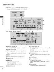
... DC power. 12 ANTENNA IN Connect over-the air signals to either input. 2 DIGITAL AUDIO OUT Connect digital audio from your TV. ANTENNA IN M.P.I. 12 13 PREPARATION 1 HDMI/DVI IN 1(DVI) 2 DIGITAL AUDIO OUT (OPTICAL) 2 3 M.P.I 4 RESET/UPDATE/REMOTE CONTROL OUT 5 SERVICE ONLY 6 RGB IN (PC) Connect the ... IN, HDMI IN Connect a HDMI (DVI) connection to this jack. 12 Note: In standby mode, these jacks. This part mainly use picture for the LCD TV models.
... DC power. 12 ANTENNA IN Connect over-the air signals to either input. 2 DIGITAL AUDIO OUT Connect digital audio from your TV. ANTENNA IN M.P.I. 12 13 PREPARATION 1 HDMI/DVI IN 1(DVI) 2 DIGITAL AUDIO OUT (OPTICAL) 2 3 M.P.I 4 RESET/UPDATE/REMOTE CONTROL OUT 5 SERVICE ONLY 6 RGB IN (PC) Connect the ... IN, HDMI IN Connect a HDMI (DVI) connection to this jack. 12 Note: In standby mode, these jacks. This part mainly use picture for the LCD TV models.

User Manual
Page 15
... G Hold the CABLE MANAGEMENT with the PROTECTIVE BRACKET and the screw as shown. CABLE MANAGEMENT 13 It will help prevent the power cable from your TV. (This feature is dropped, you may be injured or the product may be damaged. Secure the power cable with both hands and pull it backward...
... G Hold the CABLE MANAGEMENT with the PROTECTIVE BRACKET and the screw as shown. CABLE MANAGEMENT 13 It will help prevent the power cable from your TV. (This feature is dropped, you may be injured or the product may be damaged. Secure the power cable with both hands and pull it backward...

User Manual
Page 16
PROTECTIVE BRACKET BOLT CABLE HOLDER 14 Secure the power cable with the PROTECTIVE BRACKET and the screw as shown. It will help prevent the power cable from your TV. (This feature is not available for all models.) 1 To separate the CABLE HOLDER, loosen the bolt installed the set. 2 Connect the cables as necessary. To connect an additional equipment, see the EXTERNAL EQUIPMENT SETUP section. PREPARATION PREPARATION BACK COVER FOR WIRE ARRANGEMENT ■ Here shown may be somewhat different from being removed by accident. 3 Install the CABLE HOLDER as shown.
PROTECTIVE BRACKET BOLT CABLE HOLDER 14 Secure the power cable with the PROTECTIVE BRACKET and the screw as shown. It will help prevent the power cable from your TV. (This feature is not available for all models.) 1 To separate the CABLE HOLDER, loosen the bolt installed the set. 2 Connect the cables as necessary. To connect an additional equipment, see the EXTERNAL EQUIPMENT SETUP section. PREPARATION PREPARATION BACK COVER FOR WIRE ARRANGEMENT ■ Here shown may be somewhat different from being removed by accident. 3 Install the CABLE HOLDER as shown.

User Manual
Page 17
...upward. ! To connect additional equipment, see the EXTERNAL EQUIPMENT SETUP section. 2 Install the CABLE MANAGEMENT CLIP as shown. (Except 42PG60C model) If your TV has CABLE HOLDER, fix it as shown and bundle the cables. 3 Install the CABLE MANAGEMENT as necessary. NOTE G Do not hold the CABLE MANAGEMENT ...CLIP when moving the TV. - If the TV is dropped, you may be injured or the product may be broken. 15 CABLE MANAGEMENT CLIP CABLE HOLDER How to remove the CABLE ...
...upward. ! To connect additional equipment, see the EXTERNAL EQUIPMENT SETUP section. 2 Install the CABLE MANAGEMENT CLIP as shown. (Except 42PG60C model) If your TV has CABLE HOLDER, fix it as shown and bundle the cables. 3 Install the CABLE MANAGEMENT as necessary. NOTE G Do not hold the CABLE MANAGEMENT ...CLIP when moving the TV. - If the TV is dropped, you may be injured or the product may be broken. 15 CABLE MANAGEMENT CLIP CABLE HOLDER How to remove the CABLE ...
User Manual
Page 18
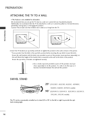
... and bolts to tighten the product to a wall so it cannot be pulled in the product. Match the height of the bracket that the TV be conveniently swivelled on the wall to tie the product. Ensure the eye-bolts or brackets are tightened securely. ■ Use a sturdy rope ...'t climb on the wall. SWIVEL STAND 20° (37LC5DC1, 42LC5DC, 42LC50C, 42PX8DC, 42LB5DC, 42LB50C, 42PG65C models) 90° (32LX5DC/S, 32LX50C/S, 32LC5DC/S, 32LC50C/S, 37LC5DC, 37LC50C models) The TV can be attached to the wall as shown in the picture. * If your product has the bolts in the eye-bolts position...
... and bolts to tighten the product to a wall so it cannot be pulled in the product. Match the height of the bracket that the TV be conveniently swivelled on the wall to tie the product. Ensure the eye-bolts or brackets are tightened securely. ■ Use a sturdy rope ...'t climb on the wall. SWIVEL STAND 20° (37LC5DC1, 42LC5DC, 42LC50C, 42PX8DC, 42LB5DC, 42LB50C, 42PG65C models) 90° (32LX5DC/S, 32LX50C/S, 32LC5DC/S, 32LC50C/S, 37LC5DC, 37LC50C models) The TV can be attached to the wall as shown in the picture. * If your product has the bolts in the eye-bolts position...

User Manual
Page 19
...32/37/42LC5DC*, 32/37/42LC50C*, 42LB5DC, 42LB50C 32LX5DC*, 32LX50C* 4-Screws Stand Desk PREPARATION 42PX8DC 4-Screws Stand Desk 42PG65C 2-Screws Stand Desk Stand 4-Screws Desk WARNING G This apparatus must be somewhat different from your TV. The TV must be securely attached to desk so it cannot be ...pulled in a forward/backward direction, potentially causing injury or damaging the product. * Screws - ATTACHING THE TV TO A DESK ■ Here shown may be attached to the floor/wall per installation instructions.Tipping, shaking, or rocking the television...
...32/37/42LC5DC*, 32/37/42LC50C*, 42LB5DC, 42LB50C 32LX5DC*, 32LX50C* 4-Screws Stand Desk PREPARATION 42PX8DC 4-Screws Stand Desk 42PG65C 2-Screws Stand Desk Stand 4-Screws Desk WARNING G This apparatus must be somewhat different from your TV. The TV must be securely attached to desk so it cannot be ...pulled in a forward/backward direction, potentially causing injury or damaging the product. * Screws - ATTACHING THE TV TO A DESK ■ Here shown may be attached to the floor/wall per installation instructions.Tipping, shaking, or rocking the television...

User Manual
Page 20
PREPARATION PREPARATION STAND INSTALLATION ( 32/37LC5DC*, 32/37LC50C* ) 1 Carefully place the product screen side down on a cushioned surface that will protect product and screen from damage. ( 42PG65C ) 1 Carefully place the TV screen side down on a cushioned surface to protect the screen from damage. 2 Assemble the product stand with the product as shown. 2 Assemble the product stand with the product as shown. 3 Securely install the 4 bolts provided as shown below. 3 Tighten the 4 bolts securely using the holes in the back of the TV. 18
PREPARATION PREPARATION STAND INSTALLATION ( 32/37LC5DC*, 32/37LC50C* ) 1 Carefully place the product screen side down on a cushioned surface that will protect product and screen from damage. ( 42PG65C ) 1 Carefully place the TV screen side down on a cushioned surface to protect the screen from damage. 2 Assemble the product stand with the product as shown. 2 Assemble the product stand with the product as shown. 3 Securely install the 4 bolts provided as shown below. 3 Tighten the 4 bolts securely using the holes in the back of the TV. 18
User Manual
Page 21
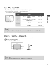
For further information, refer to the VESA Wall Mounting Instruction Guide. A B Product LCD TV Model 32LC5DC*, 32LC50C*, 32LX5DC*, 32LX50C* 32/37/42LC5DC*, 32/37/42LC50C*, 42LB5DC, 42LB50C PLASMA TV 42PG60C 42PX8DC VESA (A * B) 200 * 100 600 * 400 400 * 400 600 * 400 NOTE G Screw length needed depends on each side from the wall. ■ Image shown...
For further information, refer to the VESA Wall Mounting Instruction Guide. A B Product LCD TV Model 32LC5DC*, 32LC50C*, 32LX5DC*, 32LX50C* 32/37/42LC5DC*, 32/37/42LC50C*, 42LB5DC, 42LB50C PLASMA TV 42PG60C 42PX8DC VESA (A * B) 200 * 100 600 * 400 400 * 400 600 * 400 NOTE G Screw length needed depends on each side from the wall. ■ Image shown...

User Manual
Page 22
...installed properly, contact your dealer for outdoor antenna) Copper Wire Be careful not to bend the bronze wire when connecting the antenna. Cable Cable TV Wall Jack RF Coaxial Wire (75 ohm) Single-family Dwellings /Houses (Connect to wall antenna socket) ANTENNA IN M.P.I. Outdoor Antenna (VHF,... UHF) 2. Wall Antenna Socket Multi-family Dwellings/Apartments (Connect to wall jack for assistance. NOTE G The TV will let you know when the analog, cable, and digital channel scans are complete. 20 Antenna (Analog or Digital) Wall Antenna Socket or ...
...installed properly, contact your dealer for outdoor antenna) Copper Wire Be careful not to bend the bronze wire when connecting the antenna. Cable Cable TV Wall Jack RF Coaxial Wire (75 ohm) Single-family Dwellings /Houses (Connect to wall antenna socket) ANTENNA IN M.P.I. Outdoor Antenna (VHF,... UHF) 2. Wall Antenna Socket Multi-family Dwellings/Apartments (Connect to wall jack for assistance. NOTE G The TV will let you know when the analog, cable, and digital channel scans are complete. 20 Antenna (Analog or Digital) Wall Antenna Socket or ...


