
Brochure
Page 1
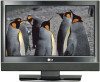
... STAR Partner LGE U. has determined that this manual carefully before operating your dealer when you require service. Environmental Protection Agency(EPA). LCD TV OWNER'S MANUAL LCD TV MODELS 20LS7D 20LS7DC 23LS7D 23LS7DC Please read this product meets the ENERGY STAR guidelines for future reference. Retain it for energy efficiency. www.lgusa.com / www...
... STAR Partner LGE U. has determined that this manual carefully before operating your dealer when you require service. Environmental Protection Agency(EPA). LCD TV OWNER'S MANUAL LCD TV MODELS 20LS7D 20LS7DC 23LS7D 23LS7DC Please read this product meets the ENERGY STAR guidelines for future reference. Retain it for energy efficiency. www.lgusa.com / www...

Brochure
Page 3
.... The lightning flash with the instructions, may be determined by turning the equipment off and on a circuit different from LG Electronics. NOTE TO CABLE/TV INSTALLER This reminder is intended to alert the user to provide reasonable protection against harmful interference in the literature accompanying the ...appliance. These limits are designed to the presence of the cable entry as practical. Consult the dealer or an experienced radio/TV technician for a Class B digital device, pursuant to Part 15 of electric shock to constitute a risk of the FCC Rules. ...
.... The lightning flash with the instructions, may be determined by turning the equipment off and on a circuit different from LG Electronics. NOTE TO CABLE/TV INSTALLER This reminder is intended to alert the user to provide reasonable protection against harmful interference in the literature accompanying the ...appliance. These limits are designed to the presence of the cable entry as practical. Consult the dealer or an experienced radio/TV technician for a Class B digital device, pursuant to Part 15 of electric shock to constitute a risk of the FCC Rules. ...

Brochure
Page 6
... Caption Option 54 User Mode 41 - EZ Picture - Color Tone - CONTENTS WARNING / CAUTION 1 SAFETY INSTRUCTIONS 2 INTRODUCTION 6 Feature of this TV 6 PREPARATION Accessories 7 Front Panel Information 8 Back Panel Information 9 Stand Installation 10 Detaching Stand 11 Back Cover for Wire Arrangement 12 Positioning your... display 13 VESA Wall Mounting 14 Desktop Pedestal Installation 14 Kensington Security System 15 Attaching the TV to a Desk 15 Antenna or Cable Connection 16 EXTERNAL EQUIPMENT SETUP HD Receiver Setup 17 DVD Setup 20 VCR ...
... Caption Option 54 User Mode 41 - EZ Picture - Color Tone - CONTENTS WARNING / CAUTION 1 SAFETY INSTRUCTIONS 2 INTRODUCTION 6 Feature of this TV 6 PREPARATION Accessories 7 Front Panel Information 8 Back Panel Information 9 Stand Installation 10 Detaching Stand 11 Back Cover for Wire Arrangement 12 Positioning your... display 13 VESA Wall Mounting 14 Desktop Pedestal Installation 14 Kensington Security System 15 Attaching the TV to a Desk 15 Antenna or Cable Connection 16 EXTERNAL EQUIPMENT SETUP HD Receiver Setup 17 DVD Setup 20 VCR ...
Brochure
Page 7
... & French (for USA only) . . 64 - TV Rating Children & General (for Canada only) . . 65 APPENDIX Troubleshooting 66 Maintenance 68 Product Specifications 69 External Control Through RS-232C 70 5 TIME SETTING Clock Setting ... / RATINGS Set Password & Lock System 60 Setting up Your Password 60 Set Password 61 Lock System 61 Channel Blocking 62 External Input Blocking 62 Movie & TV Rating 63 - Movie Rating (MPAA 63 -
... & French (for USA only) . . 64 - TV Rating Children & General (for Canada only) . . 65 APPENDIX Troubleshooting 66 Maintenance 68 Product Specifications 69 External Control Through RS-232C 70 5 TIME SETTING Clock Setting ... / RATINGS Set Password & Lock System 60 Setting up Your Password 60 Set Password 61 Lock System 61 Channel Blocking 62 External Input Blocking 62 Movie & TV Rating 63 - Movie Rating (MPAA 63 -

Brochure
Page 8
If the TV feels cold to the regulations of your finger(s) against it is nothing wrong with general household waste. However, they have no adverse effect on the ... normal, there is turned on the screen. On Disposal a. Do not dispose of this product with TV. Disposal of this product must be visible on the monitor's performance. A subset of Dolby Laboratories. INTRODUCTION FEATURE OF THIS TV LG's own special digital image generator, consisting of mercury. Manufactured under license from Dolby Laboratories. The...
If the TV feels cold to the regulations of your finger(s) against it is nothing wrong with general household waste. However, they have no adverse effect on the ... normal, there is turned on the screen. On Disposal a. Do not dispose of this product with TV. Disposal of this product must be visible on the monitor's performance. A subset of Dolby Laboratories. INTRODUCTION FEATURE OF THIS TV LG's own special digital image generator, consisting of mercury. Manufactured under license from Dolby Laboratories. The...

Brochure
Page 9
... contact the dealer where you purchased the product. D-sub 15 pin Cable 7 Owner's Manual LCD TV Owner's Manual http://www.lgusa.com www.lg.ca Copyright© 2007 LGE, All Rights Reserved. 7 5 3 - 8 6 0 9 BACK FAV MUTE C CH EXIT TV SAP POWER PICTURE 1 SOUND INPUT 4 2 TIMER 7 5 3 - 8 6 0 9 VOL BACK FAV MUTE MENU CC CH ADJUST EXIT...
... contact the dealer where you purchased the product. D-sub 15 pin Cable 7 Owner's Manual LCD TV Owner's Manual http://www.lgusa.com www.lg.ca Copyright© 2007 LGE, All Rights Reserved. 7 5 3 - 8 6 0 9 BACK FAV MUTE C CH EXIT TV SAP POWER PICTURE 1 SOUND INPUT 4 2 TIMER 7 5 3 - 8 6 0 9 VOL BACK FAV MUTE MENU CC CH ADJUST EXIT...

Brochure
Page 10
Then wipe the stand with polishing cloth. 8 When the TV is turned on, the indicator blinks green and then illuminates green before the picture is displayed. ! NOTE G If your TV. POWER INPUT MENU ENTER VOLUME CHANNEL Button Button Button Button (F,G)Buttons (E,D)Buttons /I Here shown may be somewhat different from your TV stand has a protection film, remove it attached to the stand. PREPARATION PREPARATION FRONT PANEL INFORMATION I INPUT MENU ENTER VOL CH Remote Control Sensor Power Standby Indicator Illuminates red in standby mode.
Then wipe the stand with polishing cloth. 8 When the TV is turned on, the indicator blinks green and then illuminates green before the picture is displayed. ! NOTE G If your TV. POWER INPUT MENU ENTER VOLUME CHANNEL Button Button Button Button (F,G)Buttons (E,D)Buttons /I Here shown may be somewhat different from your TV stand has a protection film, remove it attached to the stand. PREPARATION PREPARATION FRONT PANEL INFORMATION I INPUT MENU ENTER VOL CH Remote Control Sensor Power Standby Indicator Illuminates red in standby mode.

Brochure
Page 11
... AUDIO IN (RGB/DVI) L(MONO) R 5 H/P RS-232C IN (CONTROL & SERVICE) 8 7 VIDEO AUDIO COMPONENT IN 6 1 SERVICE ONLY 2 HDMI/DVI IN Connect a HDMI signal to operate the TV on DC power. 9 BACK PANEL INFORMATION I Here shown may be somewhat different from your...
... AUDIO IN (RGB/DVI) L(MONO) R 5 H/P RS-232C IN (CONTROL & SERVICE) 8 7 VIDEO AUDIO COMPONENT IN 6 1 SERVICE ONLY 2 HDMI/DVI IN Connect a HDMI signal to operate the TV on DC power. 9 BACK PANEL INFORMATION I Here shown may be somewhat different from your...

Brochure
Page 12
PREPARATION PREPARATION STAND INSTALLATION I Here shown may be somewhat different from damage. 3 Place the product stand on the product as shown. 10 stand body cover base 2 Carefully place the product screen side down on a cushioned surface that will protect product and screen from your TV. 1 Assemble parts of the stand body with cover base of the stand. Insert the stand body into a cover base until clicking sound.
PREPARATION PREPARATION STAND INSTALLATION I Here shown may be somewhat different from damage. 3 Place the product stand on the product as shown. 10 stand body cover base 2 Carefully place the product screen side down on a cushioned surface that will protect product and screen from your TV. 1 Assemble parts of the stand body with cover base of the stand. Insert the stand body into a cover base until clicking sound.

Brochure
Page 13
PREPARATION DETACHING STAND I Here shown may be somewhat different from your TV. 1 Carefully place the product screen side down on a cushioned surface that will protect product and screen from damage. 2 Pull cover base backward while pressing button on stand body. 3 Shake the base while pulling, it will separate from stand body. 4 Hold the stand and bend it upward. 5 Pull stand body to separate from set while press- ing the 2 latches. 11
PREPARATION DETACHING STAND I Here shown may be somewhat different from your TV. 1 Carefully place the product screen side down on a cushioned surface that will protect product and screen from damage. 2 Pull cover base backward while pressing button on stand body. 3 Shake the base while pulling, it will separate from stand body. 4 Hold the stand and bend it upward. 5 Pull stand body to separate from set while press- ing the 2 latches. 11

Brochure
Page 14
PREPARATION PREPARATION BACK COVER FOR WIRE ARRANGEMENT I Here shown may be somewhat different from your TV. 1 Connect the cables as shown. To connect an additional equipment, see the EXTERNAL EQUIPMENT SETUP section. 2 Install the CABLE MANAGEMENT as necessary. How to remove the CABLE MANAGEMENT First, press the cable management. Hold the CABLE MANAGEMENT with both hands and pull it upward. ! NOTE G Do not hold the CABLE MANAGEMENT when moving the product. - If the product is dropped, you may be injured or the product may be broken. 12
PREPARATION PREPARATION BACK COVER FOR WIRE ARRANGEMENT I Here shown may be somewhat different from your TV. 1 Connect the cables as shown. To connect an additional equipment, see the EXTERNAL EQUIPMENT SETUP section. 2 Install the CABLE MANAGEMENT as necessary. How to remove the CABLE MANAGEMENT First, press the cable management. Hold the CABLE MANAGEMENT with both hands and pull it upward. ! NOTE G Do not hold the CABLE MANAGEMENT when moving the product. - If the product is dropped, you may be injured or the product may be broken. 12

Brochure
Page 15
PREPARATION POSITIONING YOUR DISPLAY I Adjust the position of the panel in various ways for maximum comfort. • Tilt range 12~10 03 13 I Here shown may be somewhat different from your TV.
PREPARATION POSITIONING YOUR DISPLAY I Adjust the position of the panel in various ways for maximum comfort. • Tilt range 12~10 03 13 I Here shown may be somewhat different from your TV.

Brochure
Page 17
... or rocking the machine may cause injury/death. 15 The Kensington Security System is equipped with the Kensington Security System. The TV is an optional accessory. Kensington sells security systems for expensive electronic equipment such as shown below. - ATTACHING THE... TV TO A DESK (Only 23 inches) We recommend that the TV be attached to a desk so it cannot be pulled in a forward/backward direction, potentially causing injury or damaging the product. ...
... or rocking the machine may cause injury/death. 15 The Kensington Security System is equipped with the Kensington Security System. The TV is an optional accessory. Kensington sells security systems for expensive electronic equipment such as shown below. - ATTACHING THE... TV TO A DESK (Only 23 inches) We recommend that the TV be attached to a desk so it cannot be pulled in a forward/backward direction, potentially causing injury or damaging the product. ...

Brochure
Page 18
... in a poor signal area, please purchase a signal amplifier and install properly. Using both cable and antenna ANTENNA/ CABLE IN Antenna Cable TV Wall Jack RF Coaxial Wire (75 ohm) RF Coaxial Wire (75 ohm) Diplexer (Signal Combiner) ANTENNA/ ACNATBELNENIAN/ CABLE IN Antenna UHF... Signal Amplifier VHF ANTENNA/ CABLE IN I If the antenna needs to be split for two TV's, install a 2-Way Signal Splitter. Cable Multi-family Dwellings/Apartments (Connect to wall antenna socket) RF Coaxial Wire (75 ohm) ANTENNA/ CABLE...
... in a poor signal area, please purchase a signal amplifier and install properly. Using both cable and antenna ANTENNA/ CABLE IN Antenna Cable TV Wall Jack RF Coaxial Wire (75 ohm) RF Coaxial Wire (75 ohm) Diplexer (Signal Combiner) ANTENNA/ ACNATBELNENIAN/ CABLE IN Antenna UHF... Signal Amplifier VHF ANTENNA/ CABLE IN I If the antenna needs to be split for two TV's, install a 2-Way Signal Splitter. Cable Multi-family Dwellings/Apartments (Connect to wall antenna socket) RF Coaxial Wire (75 ohm) ANTENNA/ CABLE...

Brochure
Page 19
... set top box to 2 the COMPONENT IN AUDIO jacks on the set -top box. Y PB PR L R I Turn on the remote control. HD RECEIVER SETUP This TV can receive Digital Over-the-air/Cable signals without an external digital set -top box. (Refer to the figure as shown below. Match the jack...
... set top box to 2 the COMPONENT IN AUDIO jacks on the set -top box. Y PB PR L R I Turn on the remote control. HD RECEIVER SETUP This TV can receive Digital Over-the-air/Cable signals without an external digital set -top box. (Refer to the figure as shown below. Match the jack...
Brochure
Page 20
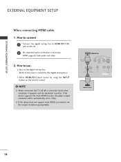
... by using the I N P U T button on the set -top box to connect 1 Connect the digital set . 2 No separated audio connection is necessary. NOTE G When connected, the TV will be automatically set the output resolution appropriately. SERVICE ONLY HDMI/DVI IN VIDEO AV IN S-VIDEO AUDIO L(MONO) R 1 H/P RS-232C IN (CONTROL & SERVICE) VIDEO...
... by using the I N P U T button on the set -top box to connect 1 Connect the digital set . 2 No separated audio connection is necessary. NOTE G When connected, the TV will be automatically set the output resolution appropriately. SERVICE ONLY HDMI/DVI IN VIDEO AV IN S-VIDEO AUDIO L(MONO) R 1 H/P RS-232C IN (CONTROL & SERVICE) VIDEO...

Brochure
Page 22
... 20 How to connect 1 Connect the video outputs (Y, PB, PR) of the DVD to the component input ports as shown below. Component ports on the TV Y PB PR Video output ports on the remote control.
... 20 How to connect 1 Connect the video outputs (Y, PB, PR) of the DVD to the component input ports as shown below. Component ports on the TV Y PB PR Video output ports on the remote control.

Brochure
Page 23
... best picture quality, adjust the output resolution of the DVD to 720p. EXTERNAL EQUIPMENT SETUP When connecting with an S-Video cable 1. NOTE G When connected, the TV will be automatically set . 2. How to use I Select HDMI/DVI input source by using the I Refer to the DVD player's manual for operating instructions. ! I Turn...
... best picture quality, adjust the output resolution of the DVD to 720p. EXTERNAL EQUIPMENT SETUP When connecting with an S-Video cable 1. NOTE G When connected, the TV will be automatically set . 2. How to use I Select HDMI/DVI input source by using the I Refer to the DVD player's manual for operating instructions. ! I Turn...

Brochure
Page 24
...) VIDEO AUDIO COMPONENT IN ANT OUT VIDEO L R S-VIDEO ANT IN OUTPUT SWITCH Wall Jack 2 Antenna 1. I Set VCR output switch to 3 or 4 and then tune TV to the same channel number. This phenomenon is used; How to use I Insert a video tape into the VCR and press PLAY on the VCR. (Refer... to the VCR owner's manual.) 22 I To avoid picture noise (interference), leave an adequate distance between the VCR and TV. EXTERNAL EQUIPMENT SETUP EXTERNAL EQUIPMENT SETUP VCR SETUP I If the 4:3 picture format is common to all manufactures and in socket of the VCR to the...
...) VIDEO AUDIO COMPONENT IN ANT OUT VIDEO L R S-VIDEO ANT IN OUTPUT SWITCH Wall Jack 2 Antenna 1. I Set VCR output switch to 3 or 4 and then tune TV to the same channel number. This phenomenon is used; How to use I Insert a video tape into the VCR and press PLAY on the VCR. (Refer... to the VCR owner's manual.) 22 I To avoid picture noise (interference), leave an adequate distance between the VCR and TV. EXTERNAL EQUIPMENT SETUP EXTERNAL EQUIPMENT SETUP VCR SETUP I If the 4:3 picture format is common to all manufactures and in socket of the VCR to the...

Brochure
Page 25
How to connect 1 Connect the S-VIDEO output of the set. NOTE G The picture quality is improved: compared to connect 1 Connect the AUDIO/VIDEO jacks between TV and VCR. HDMI/DVI IN ANTEN CABLE AV IN S-VIDEO VIDEO AUDIO E RGB (PC) IN L(MONO) RR H/P RS-232C IN NTROL & SERVICE) 2 VIDEO AUDIO COMPONENT ...
How to connect 1 Connect the S-VIDEO output of the set. NOTE G The picture quality is improved: compared to connect 1 Connect the AUDIO/VIDEO jacks between TV and VCR. HDMI/DVI IN ANTEN CABLE AV IN S-VIDEO VIDEO AUDIO E RGB (PC) IN L(MONO) RR H/P RS-232C IN NTROL & SERVICE) 2 VIDEO AUDIO COMPONENT ...


