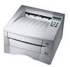
Service Manual
Page 6
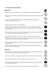
...the procedures for maintenance described in the service manual and other related brochure when replacing them can be caught in machines using lasers. They are safely secured so they will not be extremely hot • Check that the printer is correctly connected to high potentials and ...care. Precautions for Maintenance WARNING • Always remove the power plug from the printer except for installation of a part, always use the thermostat or thermal fuse specified in the service manual or other related brochures...• Under no circumstances attempt to bypass or disable ...
...the procedures for maintenance described in the service manual and other related brochure when replacing them can be caught in machines using lasers. They are safely secured so they will not be extremely hot • Check that the printer is correctly connected to high potentials and ...care. Precautions for Maintenance WARNING • Always remove the power plug from the printer except for installation of a part, always use the thermostat or thermal fuse specified in the service manual or other related brochures...• Under no circumstances attempt to bypass or disable ...

Service Manual
Page 20
... voltage. FS-1050 1-12 (2) Places to avoid Avoid installing the printer in locations exposed to: • Direct drafts of hot or cold air. • Direct drafts of outside air. (Avoid locations next to do so when performing tests described in this manual. • In connecting the printer power, ...; An easily accessible socket outlet must be exercised in handling the power cord and any other electric parts which may cause contamination on the laser scanner window, causing print quality problem. • Vibration. • Ammonia fumes or other harmful fumes. (In case of fumigating the ...
... voltage. FS-1050 1-12 (2) Places to avoid Avoid installing the printer in locations exposed to: • Direct drafts of hot or cold air. • Direct drafts of outside air. (Avoid locations next to do so when performing tests described in this manual. • In connecting the printer power, ...; An easily accessible socket outlet must be exercised in handling the power cord and any other electric parts which may cause contamination on the laser scanner window, causing print quality problem. • Vibration. • Ammonia fumes or other harmful fumes. (In case of fumigating the ...

Service Manual
Page 26
... remove the two spacers and the printed notice from the package. Remove the manuals, toner kit, and other items located on a flat, stable surface. Tapes Spacer Printed notice Figure 2-1-2 Unpacking (2) 2-3 Spacer FS-1050 Toner container (TK-17) Cleaning cloth Printer Installation guide Kyocera Mita digital library CD-ROM Figure 2-1-1 Unpacking (1) Power cord Remove the tape...
... remove the two spacers and the printed notice from the package. Remove the manuals, toner kit, and other items located on a flat, stable surface. Tapes Spacer Printed notice Figure 2-1-2 Unpacking (2) 2-3 Spacer FS-1050 Toner container (TK-17) Cleaning cloth Printer Installation guide Kyocera Mita digital library CD-ROM Figure 2-1-1 Unpacking (1) Power cord Remove the tape...

Service Manual
Page 27
Proceed as follows in the release position. 1 Figure 2-2-1 Confirming the lock lever #1 FS-1050 2-4 Open the top cover all the way. 2. If the option paper feeder is in the release (forward) position. If not, pull it forward until it is in sequence. Confirm that the lock lever #1 1 is used with the printer, begin installation with connecting the printer and the paper feeder. For details, refer to the optional Paper feeder's Service Manual. 2-2-1 Installing the toner container 1. 2-2 Installing the printer Installing the printer requires several steps.
Proceed as follows in the release position. 1 Figure 2-2-1 Confirming the lock lever #1 FS-1050 2-4 Open the top cover all the way. 2. If the option paper feeder is in the release (forward) position. If not, pull it forward until it is in sequence. Confirm that the lock lever #1 1 is used with the printer, begin installation with connecting the printer and the paper feeder. For details, refer to the optional Paper feeder's Service Manual. 2-2-1 Installing the toner container 1. 2-2 Installing the printer Installing the printer requires several steps.

Service Manual
Page 38
... Indicates either that data is being processed, or that the printer is being written to an error. Indicates a data transfer in process. Indicates that the printer is idle. 2-15 FS-1050 Indicates that the printer is online and ready. The indicator can also signal that ...you can receive data, but will not print it. 2-3 Using the operator panel This section provides explanation on how to the printer's User's Manual. 2-3-1 Operator panel The printer...
... Indicates either that data is being processed, or that the printer is being written to an error. Indicates a data transfer in process. Indicates that the printer is idle. 2-15 FS-1050 Indicates that the printer is online and ready. The indicator can also signal that ...you can receive data, but will not print it. 2-3 Using the operator panel This section provides explanation on how to the printer's User's Manual. 2-3-1 Operator panel The printer...

Service Manual
Page 51
... regulations. EcoPrint mode is made from non-harmful, flammable material, be sure to dispose of toner consumed on by drastically extending the toner container life. FS-1050 3-6 Proceed with the instructions provided in the supplied plastic bag 4 and dispose of it according to the printer's User's Manual.
... regulations. EcoPrint mode is made from non-harmful, flammable material, be sure to dispose of toner consumed on by drastically extending the toner container life. FS-1050 3-6 Proceed with the instructions provided in the supplied plastic bag 4 and dispose of it according to the printer's User's Manual.

Service Manual
Page 91
.... FS-1050 5-3 When replacing of a component, reverse the procedure for removal and replacement of the field replacement components. CAUTION When securing a self-tapping screws, align it counterclockwise, then slowly clockwise. CAUTION The printer use electrostatic sensitive parts inside (on circuit boards, Laser scanner... before touching the circuit boards, the laser scanner unit, etc. WARNING To avoid injury to most Ecosys printers. These screw symbol numbers are listed in the Ecosys Screw catalog. First turn it with this manual will help locate the component. 5-1...
.... FS-1050 5-3 When replacing of a component, reverse the procedure for removal and replacement of the field replacement components. CAUTION When securing a self-tapping screws, align it counterclockwise, then slowly clockwise. CAUTION The printer use electrostatic sensitive parts inside (on circuit boards, Laser scanner... before touching the circuit boards, the laser scanner unit, etc. WARNING To avoid injury to most Ecosys printers. These screw symbol numbers are listed in the Ecosys Screw catalog. First turn it with this manual will help locate the component. 5-1...

Service Manual
Page 143
... output on the board (See page 5-13). Check EcoPrint setting. • The EcoPrint mode can provides faint, unsharp printing because it acts to the printer's User's Manual. 6-23 FS-1050 Replace the transfer roller if necessary (See page 5-9). Check the transfer roller installation. • The transfer roller must be supported by using the operator...
... output on the board (See page 5-13). Check EcoPrint setting. • The EcoPrint mode can provides faint, unsharp printing because it acts to the printer's User's Manual. 6-23 FS-1050 Replace the transfer roller if necessary (See page 5-9). Check the transfer roller installation. • The transfer roller must be supported by using the operator...

Service Manual
Page 144
...be approximately 400 V. The developing roller (in the process unit) may be set too high. Check the surface potential of the allowable range. FS-1050 6-24 This may be defective. • If a process unit which is known to work normally is possible only by using the Remote operation...123 Check the print density setting. • The print density may vary depending on production lots. The drum unit will have to the printer's User's Manual. Try adjusting the print density using the jig and tool specifically designed for check, replace the current process unit in the process unit)....
...be approximately 400 V. The developing roller (in the process unit) may be set too high. Check the surface potential of the allowable range. FS-1050 6-24 This may be defective. • If a process unit which is known to work normally is possible only by using the Remote operation...123 Check the print density setting. • The print density may vary depending on production lots. The drum unit will have to the printer's User's Manual. Try adjusting the print density using the jig and tool specifically designed for check, replace the current process unit in the process unit)....

Service Manual
Page 160
... status page To print a service status page, using the MENU key. Connect the printer to print. 3. Ensure that the printer is printed.) Service information on the status page FS-1050 B-3 Information on the user (normal) status page, refer to the printer's User's Manual. STAT 1; EXIT; >lpt1: The service status page is printed. (If you omit '1,' a user...
... status page To print a service status page, using the MENU key. Connect the printer to print. 3. Ensure that the printer is printed.) Service information on the status page FS-1050 B-3 Information on the user (normal) status page, refer to the printer's User's Manual. STAT 1; EXIT; >lpt1: The service status page is printed. (If you omit '1,' a user...

Service Manual
Page 175
...Frame ground Signal ground Rx terminal Tx terminal Printer serial port (DB-25) 1 FG 3 RD− 7 SG 9 SD− 0 SD+ * RD+ On the computer serial port, investigate pin assignments depends on the computer manufacture's instruction. C-11 FS-1050 Since the RS-422A configuration does not ...employ control lines except for data transmission/reception, select a mode in which signals such as DTR are not used. For adjusting serial interface parameters including baud rate, parity, etc., refer to optional Serial interface board User's Manual....
...Frame ground Signal ground Rx terminal Tx terminal Printer serial port (DB-25) 1 FG 3 RD− 7 SG 9 SD− 0 SD+ * RD+ On the computer serial port, investigate pin assignments depends on the computer manufacture's instruction. C-11 FS-1050 Since the RS-422A configuration does not ...employ control lines except for data transmission/reception, select a mode in which signals such as DTR are not used. For adjusting serial interface parameters including baud rate, parity, etc., refer to optional Serial interface board User's Manual....


