
Instruction Manual
Page 3
... screen • Parametric Equalizer Position 72 • Displaying the Position screen • Position Fine Control Zone Control 74 • Displaying the Zone Control screen Before Installation 76 Connection 78 Installation 81 Glossary 86 Troubleshooting Guide 87 Specifications 92 English 3
... screen • Parametric Equalizer Position 72 • Displaying the Position screen • Position Fine Control Zone Control 74 • Displaying the Zone Control screen Before Installation 76 Connection 78 Installation 81 Glossary 86 Troubleshooting Guide 87 Specifications 92 English 3
Instruction Manual
Page 4
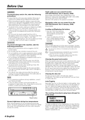
... the LCD contacts your Kenwood dealer. • Do not touch the liquid crystal fluid if the LCD is damaged or broken due to shock. To enjoy TV/video pictures, find a safe place to evaporate. If that the unit is securely installed. Audio units you can control from the XXV-05V Receiver (As of January...
... the LCD contacts your Kenwood dealer. • Do not touch the liquid crystal fluid if the LCD is damaged or broken due to shock. To enjoy TV/video pictures, find a safe place to evaporate. If that the unit is securely installed. Audio units you can control from the XXV-05V Receiver (As of January...

Instruction Manual
Page 76
Before Installation Accessories 1 2 3 4 5 6 7 8 9 0 - ..........1 ..........1 = ..........1 ~ ..........1 ! ..........1 @ ..........1 # ..........2 $ ..........4 % ..........4 ^ ..........2 76 English ..........2 ..........4 ..........4 ..........4 ..........2 ..........2 ..........4 ..........4 ..........1
Before Installation Accessories 1 2 3 4 5 6 7 8 9 0 - ..........1 ..........1 = ..........1 ~ ..........1 ! ..........1 @ ..........1 # ..........2 $ ..........4 % ..........4 ^ ..........2 76 English ..........2 ..........4 ..........4 ..........4 ..........2 ..........2 ..........4 ..........4 ..........1
Instruction Manual
Page 77
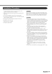
...being connected to the system, connect the connectors either to both the front output terminals or to a power source that the mounting angle is installed, check whether the brake lamps, blinkers, wipers, etc. English 77 Connect the speaker wires of the left speaker to the power source ... car. • When only two speakers are working properly. • Mount the unit so that can be damaged or fail to the unit. 6. Installation Procedure 1. Connect the wiring harness connector to work if you connect the + connector of the wiring harness. 4. Always connect those wires to a front ...
...being connected to the system, connect the connectors either to both the front output terminals or to a power source that the mounting angle is installed, check whether the brake lamps, blinkers, wipers, etc. English 77 Connect the speaker wires of the left speaker to the power source ... car. • When only two speakers are working properly. • Mount the unit so that can be damaged or fail to the unit. 6. Installation Procedure 1. Connect the wiring harness connector to work if you connect the + connector of the wiring harness. 4. Always connect those wires to a front ...

Instruction Manual
Page 81
...) Firewall or metal support Self-tapping screw (commercially available) Bend the tabs of the hideaway unit using the sems bolts 8. Attach the installation brackets 0 to the audio board. Metal mounting strap (commercially available) Accessory 6 Make sure that the unit is unstable, it in place.... Installation brackets (Accessory 0) Sems bolts (M4×8 mm) (Accessory 8) 2. Use the tapping screw 9 to secure the hideaway unit to the sides of the...
...) Firewall or metal support Self-tapping screw (commercially available) Bend the tabs of the hideaway unit using the sems bolts 8. Attach the installation brackets 0 to the audio board. Metal mounting strap (commercially available) Accessory 6 Make sure that the unit is unstable, it in place.... Installation brackets (Accessory 0) Sems bolts (M4×8 mm) (Accessory 8) 2. Use the tapping screw 9 to secure the hideaway unit to the sides of the...
Instruction Manual
Page 82
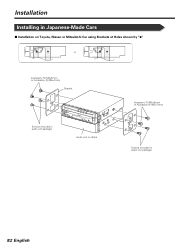
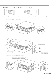
Installation Installing in Japanese-Made Cars ■ Installation on Toyota, Nissan or Mitsubishi Car using Brackets at Holes shown by "¶" or Accessory $ (M5×6mm) or Accessory % (M5×7mm) Bracket Screws (included in audio unit package) Audio unit or others Accessory $ (M5×6mm) or Accessory % (M5×7mm) Screws (included in audio unit package) 82 English
Installation Installing in Japanese-Made Cars ■ Installation on Toyota, Nissan or Mitsubishi Car using Brackets at Holes shown by "¶" or Accessory $ (M5×6mm) or Accessory % (M5×7mm) Bracket Screws (included in audio unit package) Audio unit or others Accessory $ (M5×6mm) or Accessory % (M5×7mm) Screws (included in audio unit package) 82 English
Instruction Manual
Page 83
... or pliers, and bend each side. Use accessories # at both sides as shown below. 1. Mount the bracket at each accessory tab into the hole of installation bracket to fix the bracket. Screws (included in audio unit package) 3. Accessory # Audio unit or others 2. Bend each end of the right and left unit... sides. If so, tighten the bracket using the bracket shown above, you cannot use screws at two holes of accessory # to fix the bracket. ■ Installation on Toyota Car using Brackets at Holes shown by "¶" or When using accessories # as shown.
... or pliers, and bend each side. Use accessories # at both sides as shown below. 1. Mount the bracket at each accessory tab into the hole of installation bracket to fix the bracket. Screws (included in audio unit package) 3. Accessory # Audio unit or others 2. Bend each end of the right and left unit... sides. If so, tighten the bracket using the bracket shown above, you cannot use screws at two holes of accessory # to fix the bracket. ■ Installation on Toyota Car using Brackets at Holes shown by "¶" or When using accessories # as shown.
Instruction Manual
Page 84
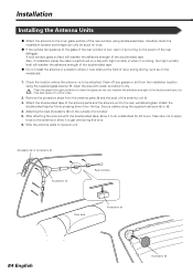
...of the antenna unit !. 3. A cold window glass surface will weaken the adhesive strength of the double-sided tape. ¶ Do not install the antenna in a location where it to sit undisturbed for 24 hours. Clean off any grease or dirt from the top. After attaching the... antenna with the double-sided tape, allow to dry. Accessory @ or Accessory # Accessory ! Installation Installing the Antenna Units ¶ Attach the antenna to the inner glass surface of the rear window using the supplied clampers @ or #. 4. Carefully check...
...of the antenna unit !. 3. A cold window glass surface will weaken the adhesive strength of the double-sided tape. ¶ Do not install the antenna in a location where it to sit undisturbed for 24 hours. Clean off any grease or dirt from the top. After attaching the... antenna with the double-sided tape, allow to dry. Accessory @ or Accessory # Accessory ! Installation Installing the Antenna Units ¶ Attach the antenna to the inner glass surface of the rear window using the supplied clampers @ or #. 4. Carefully check...

Instruction Manual
Page 92
...×1 Preout level (V 5V/10kΩ Preout impedance 80Ω General Operating voltage 14.4V (11V~16V) Current consumption 15A Dimensions (W×H×D) Main Unit Installation 182mm×53mm×165mm Hideaway unit 225mm×40mm×168mm Operational temperature range 10°C~60°C Storage temperature range 20°C~85...
...×1 Preout level (V 5V/10kΩ Preout impedance 80Ω General Operating voltage 14.4V (11V~16V) Current consumption 15A Dimensions (W×H×D) Main Unit Installation 182mm×53mm×165mm Hideaway unit 225mm×40mm×168mm Operational temperature range 10°C~60°C Storage temperature range 20°C~85...


