
Instruction Manual
Page 1
... Residence Only Register Online Register your Kenwood dealer for information or service on the warranty card, and in the space provided below. KOS-L702 WIDE TOUCH SCREEN MONITOR 7 page 2-11 INSTRUCTION MANUAL MONITEUR ECRAN LARGE TACTILE 7 page 12-21 MODE D'EMPLOI WIDE TOUCH SCREEN MONITOR 7 Seite 22-31 BEDIENUNGSANLEITUNG BREEDBEELD MONITOR MET AANRAAKSCHERM 7 blz 32-41...
... Residence Only Register Online Register your Kenwood dealer for information or service on the warranty card, and in the space provided below. KOS-L702 WIDE TOUCH SCREEN MONITOR 7 page 2-11 INSTRUCTION MANUAL MONITEUR ECRAN LARGE TACTILE 7 page 12-21 MODE D'EMPLOI WIDE TOUCH SCREEN MONITOR 7 Seite 22-31 BEDIENUNGSANLEITUNG BREEDBEELD MONITOR MET AANRAAKSCHERM 7 blz 32-41...

Instruction Manual
Page 3
...of the unit falls such as during installation, consult your Kenwood dealer. • When you purchase optional accessories, check with your Kenwood dealer to make sure that have adopted separate waste collection ... mechanical parts. If the faceplate is stained, wipe it again with a hard cloth or using the monitor for a while. Contact your area. • If the unit fails to you. English | ...from what appears on the display in the illustrations may differ from the KOS-L702 (As of March, 2007): KOS-V500, KOS-V1000 • The illustrations of the display and the panel appearing ...
...of the unit falls such as during installation, consult your Kenwood dealer. • When you purchase optional accessories, check with your Kenwood dealer to make sure that have adopted separate waste collection ... mechanical parts. If the faceplate is stained, wipe it again with a hard cloth or using the monitor for a while. Contact your area. • If the unit fails to you. English | ...from what appears on the display in the illustrations may differ from the KOS-L702 (As of March, 2007): KOS-V500, KOS-V1000 • The illustrations of the display and the panel appearing ...

Instruction Manual
Page 5
..." Setting Full picture mode Swithing the Display off mode You can set the display off mode Press any button. Press the [V.SEL] button for the monitor. Press the [FUNC] button. The screen mode of the A/V controller's manual. Switches the function screen Switches to be changed . Switching Screen Mode Press the [MODE...
..." Setting Full picture mode Swithing the Display off mode You can set the display off mode Press any button. Press the [V.SEL] button for the monitor. Press the [FUNC] button. The screen mode of the A/V controller's manual. Switches the function screen Switches to be changed . Switching Screen Mode Press the [MODE...
Instruction Manual
Page 7
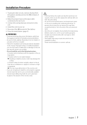
...in a location which is installed, check whether the brake lamps, blinkers, wipers, etc. on the car are located on the bottom of the monitor unit.) ¤ • If the fuse blows, first make sure that the wires have not caused a short circuit, then replace the old... electricity. To prevent short circuits, remove the key from the ends of the battery during installation. • Be sure to use a commercially available monitor stand. (Mounting holes for each unit. 3. Install the unit in this product. Reconnect the · terminal of the battery. 2. Improper wiring ...
...in a location which is installed, check whether the brake lamps, blinkers, wipers, etc. on the car are located on the bottom of the monitor unit.) ¤ • If the fuse blows, first make sure that the wires have not caused a short circuit, then replace the old... electricity. To prevent short circuits, remove the key from the ends of the battery during installation. • Be sure to use a commercially available monitor stand. (Mounting holes for each unit. 3. Install the unit in this product. Reconnect the · terminal of the battery. 2. Improper wiring ...
Instruction Manual
Page 8
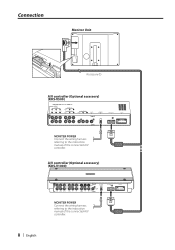
A/V controller (Optional accessory) (KOS-V1000) FM/ AM PRE OUT SUB REAR FRONT VIDEO AV IN 2 AV IN 1 VIDEO AV OUT 2 MONITOR POWER AV OUT 1 R-CAM V-IN MONITOR I/F POWER MONITER POWER Connect the wiring harness referring to the instruction manual of the connected A/V controller. 8 | English Connection Monitor Unit L ANTENNA FM/AM Accessory 1 A/V controller (Optional accessory) (KOS-V500) MONITER POWER Connect the wiring harness referring to the instruction manual of the connected A/V controller.
A/V controller (Optional accessory) (KOS-V1000) FM/ AM PRE OUT SUB REAR FRONT VIDEO AV IN 2 AV IN 1 VIDEO AV OUT 2 MONITOR POWER AV OUT 1 R-CAM V-IN MONITOR I/F POWER MONITER POWER Connect the wiring harness referring to the instruction manual of the connected A/V controller. 8 | English Connection Monitor Unit L ANTENNA FM/AM Accessory 1 A/V controller (Optional accessory) (KOS-V500) MONITER POWER Connect the wiring harness referring to the instruction manual of the connected A/V controller.
Instruction Manual
Page 9
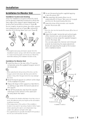
... Low temperature may damage the screw. 2 Bend the stand support to conform to the stand during this product. Installation Installation for Monitor Unit Installation location and cleaning Select for installation a location where the stand can be placed completely horizontal or where the front edge of...it to dry. 5 Secure the stand using a cloth which has been soaked in a neutral cleaning agent and wrung out. Installation for Monitor Unit 1 Install the shoe on the support. 4 Peel off the protective strip from the installation location using the supplied tapping screw (Accessory ...
... Low temperature may damage the screw. 2 Bend the stand support to conform to the stand during this product. Installation Installation for Monitor Unit Installation location and cleaning Select for installation a location where the stand can be placed completely horizontal or where the front edge of...it to dry. 5 Secure the stand using a cloth which has been soaked in a neutral cleaning agent and wrung out. Installation for Monitor Unit 1 Install the shoe on the support. 4 Peel off the protective strip from the installation location using the supplied tapping screw (Accessory ...
Instruction Manual
Page 10
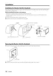
... the mounting and wiring work to be cut out of the headrest, then carefully cut it . 10 | English Before mounting the monitor to the headrest: • Perform the required external connections first (Accessory 1). • Using the supplied paper template (Accessory 7), ...mark the area to professionals. Headrest Installation plate (not supplied) Accessory 1 Accessory 5 Monitor Unit Paper template (Accessory 7) Accessory 1 Screws (not supplied) Removing the Monitor Unit (For Headrest) 1 Insert the removal tool (Accessory 6) deeply into the slots on each side, as...
... the mounting and wiring work to be cut out of the headrest, then carefully cut it . 10 | English Before mounting the monitor to the headrest: • Perform the required external connections first (Accessory 1). • Using the supplied paper template (Accessory 7), ...mark the area to professionals. Headrest Installation plate (not supplied) Accessory 1 Accessory 5 Monitor Unit Paper template (Accessory 7) Accessory 1 Screws (not supplied) Removing the Monitor Unit (For Headrest) 1 Insert the removal tool (Accessory 6) deeply into the slots on each side, as...
Instruction Manual
Page 11
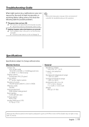
...; Press the reset button on the operation. Specifications Specifications subject to the bracket until it clicks. ? Monitor Section Screen size : 6.95 inches wide 156.2(W) × 82.4(H) × 176.0(Diagonal) mm 6-1/8(W) × 3-1/4(H) inches Display system : Transparent TN LCD panel Drive system : TFT active matrix system Number of pixels : 336,960 pixels (480 H ×...
...; Press the reset button on the operation. Specifications Specifications subject to the bracket until it clicks. ? Monitor Section Screen size : 6.95 inches wide 156.2(W) × 82.4(H) × 176.0(Diagonal) mm 6-1/8(W) × 3-1/4(H) inches Display system : Transparent TN LCD panel Drive system : TFT active matrix system Number of pixels : 336,960 pixels (480 H ×...

