Instruction Manual
Page 2
... device/ Installation/connection 20 iPod Start playing a disc Connecting a USB device Connecting an iPod Selecting Repeat Play Selecting Random Play 10 Basic procedure Warning Caution Wiring connection Installing the unit Removing the unit Selecting a folder/track/file Specifications 23 Functions of this unit with iPod Selecting a song by alphabet Selecting App...
... device/ Installation/connection 20 iPod Start playing a disc Connecting a USB device Connecting an iPod Selecting Repeat Play Selecting Random Play 10 Basic procedure Warning Caution Wiring connection Installing the unit Removing the unit Selecting a folder/track/file Specifications 23 Functions of this unit with iPod Selecting a song by alphabet Selecting App...
Instruction Manual
Page 20
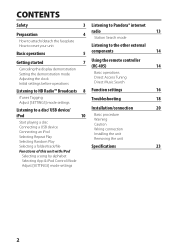
... source running through the fuse box. Insulate unconnected wires with a 12 V DC power supply, negative ground. If you experience problems during and shortly after installation. Do not touch the metal part of this unit during installation, consult your Kenwood dealer. 20 For safety's sake, leave this ...unit to professionals. Be sure to ground this work if you share the · wires or ground them to any ) when closing and opening. If you connect...
... source running through the fuse box. Insulate unconnected wires with a 12 V DC power supply, negative ground. If you experience problems during and shortly after installation. Do not touch the metal part of this unit during installation, consult your Kenwood dealer. 20 For safety's sake, leave this ...unit to professionals. Be sure to ground this work if you share the · wires or ground them to any ) when closing and opening. If you connect...
Instruction Manual
Page 21
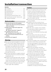
...(Antenna control wire) Blue/White (Power control wire) ANT CONT (Not used) To the power control terminal when using the optional power P. Brown (Mute control wire) To the terminal that is grounded when either the telephone rings or during conversation. (To connect the Kenwood navigation MUTE system..., consult your navigation manual.) Red (Ignition wire) Yellow (Battery wire) Black (Ground wire) Car fuse box To the metallic body or chassis of the car Ignition key switch...
...(Antenna control wire) Blue/White (Power control wire) ANT CONT (Not used) To the power control terminal when using the optional power P. Brown (Mute control wire) To the terminal that is grounded when either the telephone rings or during conversation. (To connect the Kenwood navigation MUTE system..., consult your navigation manual.) Red (Ignition wire) Yellow (Battery wire) Black (Ground wire) Car fuse box To the metallic body or chassis of the car Ignition key switch...
Instruction Manual
Page 22
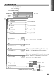
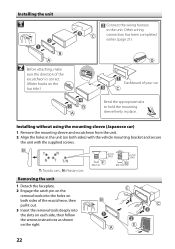
.... 2 Engage the catch pin on the removal tools into the holes on both sides of your car Bend the appropriate tabs to the unit. Other wiring connection has been completed earlier. (page 21) 2 Before attaching, make sure the direction of the escutcheon is correct. (Wider hooks on the top side.) Dashboard... arrows instructions as shown on both sides) with the vehicle mounting bracket and secure the unit with the supplied screws. Installing the unit 1 Connect the wiring harness to hold the mounting sleeve firmly in the unit (on the right. 22
.... 2 Engage the catch pin on the removal tools into the holes on both sides of your car Bend the appropriate tabs to the unit. Other wiring connection has been completed earlier. (page 21) 2 Before attaching, make sure the direction of the escutcheon is correct. (Wider hooks on the top side.) Dashboard... arrows instructions as shown on both sides) with the vehicle mounting bracket and secure the unit with the supplied screws. Installing the unit 1 Connect the wiring harness to hold the mounting sleeve firmly in the unit (on the right. 22


