
Operation Manual
Page 1
Familiarity with installation and operation procedures will help you call upon your Kenwood dealer for information or service on the warranty card, and in the space provided below. CMOS-320 CMOS-220 UNIVERSAL MULTI-VIEW CAMERA/ UNIVERSAL REAR VIEW CAMERA INSTRUCTION MANUAL CAMÉRA MULTI-VUES UNIVERSELLE/ CAMÉRA DE RECUL UNIVERSELLE MODE D'EMPLOI...
Familiarity with installation and operation procedures will help you call upon your Kenwood dealer for information or service on the warranty card, and in the space provided below. CMOS-320 CMOS-220 UNIVERSAL MULTI-VIEW CAMERA/ UNIVERSAL REAR VIEW CAMERA INSTRUCTION MANUAL CAMÉRA MULTI-VUES UNIVERSELLE/ CAMÉRA DE RECUL UNIVERSELLE MODE D'EMPLOI...

Operation Manual
Page 3
... cord contacts a high-temperature area of the unconnected wires or the terminals. • After the unit is to the Instruction's manual for details on connecting the other similar material. Always connect those wires to the unit. - If the insulation of the wiring melts... prevent a short circuit, do not remove the caps on the car body treated with camera bracket) ..........1 Power cord ..........1 CMOS-320 CMOS-220 Grommet ..........1 Camera bracket clamping screw..........1 CMOS-320 only Switch unit..........1 Double-side adhesive tape ..........1 CMOS-320/CMOS-220 | 3 ENGLISH
... cord contacts a high-temperature area of the unconnected wires or the terminals. • After the unit is to the Instruction's manual for details on connecting the other similar material. Always connect those wires to the unit. - If the insulation of the wiring melts... prevent a short circuit, do not remove the caps on the car body treated with camera bracket) ..........1 Power cord ..........1 CMOS-320 CMOS-220 Grommet ..........1 Camera bracket clamping screw..........1 CMOS-320 only Switch unit..........1 Double-side adhesive tape ..........1 CMOS-320/CMOS-220 | 3 ENGLISH
Operation Manual
Page 5
... the camera cord. When the camera is installed as a front camera (CMOS-320 only): Refer to the instruction manual of the unit that the rear of the vehicle. Vehicle rear part or bumper When installing CMOS-320 as a front camera: When you select [Lower] for "Mounting Position Setting...to [Overhead View] (page 14) and adjust the camera angle so that the guideline and the parking lines become vertical. Guideline Next page 3 CMOS-320/CMOS-220 | 5 Otherwise, an unexpected accident may result. When you select [Standard] for "Mounting Position Setting", refer to page 9 to 13 ...
... the camera cord. When the camera is installed as a front camera (CMOS-320 only): Refer to the instruction manual of the unit that the rear of the vehicle. Vehicle rear part or bumper When installing CMOS-320 as a front camera: When you select [Lower] for "Mounting Position Setting...to [Overhead View] (page 14) and adjust the camera angle so that the guideline and the parking lines become vertical. Guideline Next page 3 CMOS-320/CMOS-220 | 5 Otherwise, an unexpected accident may result. When you select [Standard] for "Mounting Position Setting", refer to page 9 to 13 ...

Operation Manual
Page 10
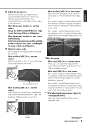
... the frame of the camera. buttons on the position corresponding to the center line of 50cm to 80cm (1.64feet to 2.62feet). 10 | CMOS-320/CMOS-220 Adjustment is not possible in an individual adjustment item resets the camera setting of that the two white lines appear on the switch unit...[Standard] when installing the camera at a height of the switch unit so that item to yellow. For displaying the camera video, read the instruction manual for camera adjustment. 1. button to select an item and press the view button to enter the adjusted value. 7 End the setting. Overhead View...
... the frame of the camera. buttons on the position corresponding to the center line of 50cm to 80cm (1.64feet to 2.62feet). 10 | CMOS-320/CMOS-220 Adjustment is not possible in an individual adjustment item resets the camera setting of that the two white lines appear on the switch unit...[Standard] when installing the camera at a height of the switch unit so that item to yellow. For displaying the camera video, read the instruction manual for camera adjustment. 1. button to select an item and press the view button to enter the adjusted value. 7 End the setting. Overhead View...

Operation Manual
Page 13
...unit to select [Finish] and press the view button. Advances to [Front Camera]. 1 Install the switch unit. CMOS-320/CMOS-220 | 13 Camera ID Setting When connecting a CMOS-320 as a front camera to a Kenwood navigation system equipped with the camera control function, it . 3 Press and hold the - button of the front ... ADJUSTMENT (Red Line Position Setting)". 2 Press the + or - Move the red line until the edge of the red line. to the instruction manual of the red line displayed in the monitor, move the red line around the edge of the switch unit to select [Finish] and press the...
...unit to select [Finish] and press the view button. Advances to [Front Camera]. 1 Install the switch unit. CMOS-320/CMOS-220 | 13 Camera ID Setting When connecting a CMOS-320 as a front camera to a Kenwood navigation system equipped with the camera control function, it . 3 Press and hold the - button of the front ... ADJUSTMENT (Red Line Position Setting)". 2 Press the + or - Move the red line until the edge of the red line. to the instruction manual of the red line displayed in the monitor, move the red line around the edge of the switch unit to select [Finish] and press the...
Operation Manual
Page 59
... are designed to which can be determined by turning the equipment off and on a circuit different from that interference will not occur in the instruction manual. Yaşadığınız bölgeye en yakın geri dönüşüm tesisinin yerini öğrenmek için uygulanabilir...
... are designed to which can be determined by turning the equipment off and on a circuit different from that interference will not occur in the instruction manual. Yaşadığınız bölgeye en yakın geri dönüşüm tesisinin yerini öğrenmek için uygulanabilir...


