
Installation Manual
Page 1
KVT-819DVD KVT-839DVD MONITOR WITH DVD RECEIVER INSTALLATION MANUAL MONITOR CON RECEPTOR DVD MANUAL DE INSTALACIÓN © B54-4552-00/00 (KV/RV)
KVT-819DVD KVT-839DVD MONITOR WITH DVD RECEIVER INSTALLATION MANUAL MONITOR CON RECEPTOR DVD MANUAL DE INSTALACIÓN © B54-4552-00/00 (KV/RV)
Installation Manual
Page 3
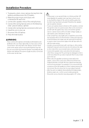
... key. Therefore, the speaker wire should be checked. • If your car. 7. For example, if you connect the + connector of the vehicle and the protection function may die. • If the console has a lid, make sure to install the unit so that can be damaged or fail to work if you connect the ignition wire to the power source running through the fuse box. •...
... key. Therefore, the speaker wire should be checked. • If your car. 7. For example, if you connect the + connector of the vehicle and the protection function may die. • If the console has a lid, make sure to install the unit so that can be damaged or fail to work if you connect the ignition wire to the power source running through the fuse box. •...
Installation Manual
Page 4
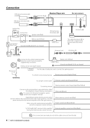
... remote control input (Light Blue/Yellow) Mute wire (Brown) Motor antenna control wire (Blue) Power control wire (Blue/White) External amplifier control wire (Pink/Black) If no connections are using the supplied relay connector. Connection USB device (commercially available) USB connector (iPod) Monitor/Player unit iPod USB device (commercially available) USB connector Do not connect. Parking sensor wire (Light Green) Battery wire (Yellow) FUSE ( 10A ) A Ground wire (Black) - (To car chassis) PRK SW For the sake of the amplifier having the external amp control function...
... remote control input (Light Blue/Yellow) Mute wire (Brown) Motor antenna control wire (Blue) Power control wire (Blue/White) External amplifier control wire (Pink/Black) If no connections are using the supplied relay connector. Connection USB device (commercially available) USB connector (iPod) Monitor/Player unit iPod USB device (commercially available) USB connector Do not connect. Parking sensor wire (Light Green) Battery wire (Yellow) FUSE ( 10A ) A Ground wire (Black) - (To car chassis) PRK SW For the sake of the amplifier having the external amp control function...
Installation Manual
Page 5
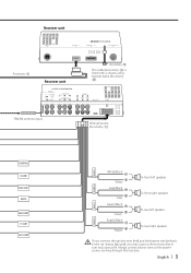
... in turn may start a fire. English | 5 Receiver unit Accessory 3 Receiver unit Accessory @ The cable (Accessory 3) is fixed with a chassis using harness band (Accessory @). FM/AM antenna input Wiring harness (Accessory 1) REVERSE ILLUMI REMO.CONT MUTE ANT CONT P. CONT FRONT L FRONT R White/Black White + Gray/Black + Gray Green/Black + Green Purple/Black Purple + To front left speaker To front right speaker To rear left speaker To rear right speaker REAR L REAR R If you connect the ignition wire (red) and the battery wire (yellow) to the power source...
... in turn may start a fire. English | 5 Receiver unit Accessory 3 Receiver unit Accessory @ The cable (Accessory 3) is fixed with a chassis using harness band (Accessory @). FM/AM antenna input Wiring harness (Accessory 1) REVERSE ILLUMI REMO.CONT MUTE ANT CONT P. CONT FRONT L FRONT R White/Black White + Gray/Black + Gray Green/Black + Green Purple/Black Purple + To front left speaker To front right speaker To rear left speaker To rear right speaker REAR L REAR R If you connect the ignition wire (red) and the battery wire (yellow) to the power source...
Installation Manual
Page 6
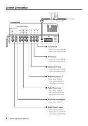
... Receiver unit RELAY 2 RELAY 1 Accessory # To Relay Box 6 | KVT-819DVD/KVT-839DVD ■ Front Preout • Audio left output (White) • Audio right output (Red) ■ Rear Preout • Audio left output (White) • Audio right output (Red) ■ Subwoofer Preout • Audio left output (White) • Audio right output (Red) ■ Audio/Visual input 2 • Visual input (Yellow) • Audio left input (White) • Audio right input (Red) ■ Audio/Visual input 1 • Visual input (Yellow) • Audio left input (White) • Audio right input (Red...
... Receiver unit RELAY 2 RELAY 1 Accessory # To Relay Box 6 | KVT-819DVD/KVT-839DVD ■ Front Preout • Audio left output (White) • Audio right output (Red) ■ Rear Preout • Audio left output (White) • Audio right output (Red) ■ Subwoofer Preout • Audio left output (White) • Audio right output (Red) ■ Audio/Visual input 2 • Visual input (Yellow) • Audio left input (White) • Audio right input (Red) ■ Audio/Visual input 1 • Visual input (Yellow) • Audio left input (White) • Audio right input (Red...
Installation Manual
Page 7
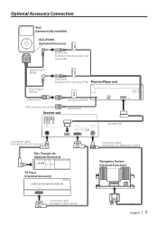
... Disc changer) Disc Changer etc. (Optional Accessory) TV Tuner (Optional Accessory) Connection cable (Included in the Navigation System) Navigation System (Optional Accessory) TV ANTENNA INPUT TO MONITOR UNIT Connection cable (Included in the TV tuner) English | 7 Optional Accessory Connection iPod AUDIO IN iPod (commercially available) KCA-iP300V (Optional Accessory) Audio Input Resistance-free stereo type mini plug (3.5Ф) iPod VIDEO IN Audio Output (Black) Visual Output (Yellow) Visual Input Resistance-free mini plug (3.5Ф) Monitor/Player unit iPod USB terminal iPod...
... Disc changer) Disc Changer etc. (Optional Accessory) TV Tuner (Optional Accessory) Connection cable (Included in the Navigation System) Navigation System (Optional Accessory) TV ANTENNA INPUT TO MONITOR UNIT Connection cable (Included in the TV tuner) English | 7 Optional Accessory Connection iPod AUDIO IN iPod (commercially available) KCA-iP300V (Optional Accessory) Audio Input Resistance-free stereo type mini plug (3.5Ф) iPod VIDEO IN Audio Output (Black) Visual Output (Yellow) Visual Input Resistance-free mini plug (3.5Ф) Monitor/Player unit iPod USB terminal iPod...
Installation Manual
Page 8
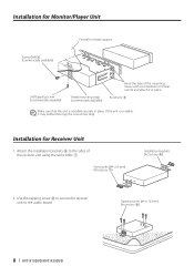
... receiver unit using the sems bolts 7. Use the tapping screw 8 to secure the receiver unit to the sides of the mounting sleeve with a screwdriver or similar utensil and attach it may malfunction (eg, the sound may skip). Tapping screw (ø4 × 16 mm) (Accessory 8) 8 | KVT-819DVD/KVT-839DVD Sems bolts (M4 × 8 mm) (Accessory 7) Installation brackets (Accessory 9) 2. Installation for Receiver Unit 1. Accessory 5 Make...
... receiver unit using the sems bolts 7. Use the tapping screw 8 to secure the receiver unit to the sides of the mounting sleeve with a screwdriver or similar utensil and attach it may malfunction (eg, the sound may skip). Tapping screw (ø4 × 16 mm) (Accessory 8) 8 | KVT-819DVD/KVT-839DVD Sems bolts (M4 × 8 mm) (Accessory 7) Installation brackets (Accessory 9) 2. Installation for Receiver Unit 1. Accessory 5 Make...
Installation Manual
Page 9
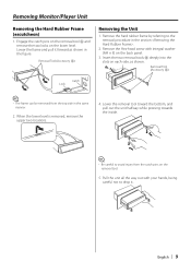
... it . When the lower level is removed, remove the upper two locations. 4. Removal Tool (Accessory 6) Catch Lock ⁄ • The frame can be removed from the catch pins on the lower level. Remove the Hex-head screw with your hands, being careful not to avoid injury from the top side in the same manner. 2. Removing Monitor/Player Unit Removing the Hard Rubber Frame (escutcheon) 1.
... it . When the lower level is removed, remove the upper two locations. 4. Removal Tool (Accessory 6) Catch Lock ⁄ • The frame can be removed from the catch pins on the lower level. Remove the Hex-head screw with your hands, being careful not to avoid injury from the top side in the same manner. 2. Removing Monitor/Player Unit Removing the Hard Rubber Frame (escutcheon) 1.
Installation Manual
Page 10
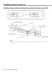
If you use your own screws. Installing in Japanese-made Cars Installation on Toyota, Nissan or Mitsubishi Car using Brackets at Holes shown by "●" or Accessory 0 (M5x6mm) or Accessory ! (M5x7mm) Car Bracket Accessory 0 (M5x6mm) or Accessory ! (M5x7mm) Screws (included in audio unit package) Audio unit or others Screws (included in audio unit package) ⁄ • Do not use the wrong screws, you could damage the unit. 10 | KVT-819DVD/KVT-839DVD Use only the screws provided.
If you use your own screws. Installing in Japanese-made Cars Installation on Toyota, Nissan or Mitsubishi Car using Brackets at Holes shown by "●" or Accessory 0 (M5x6mm) or Accessory ! (M5x7mm) Car Bracket Accessory 0 (M5x6mm) or Accessory ! (M5x7mm) Screws (included in audio unit package) Audio unit or others Screws (included in audio unit package) ⁄ • Do not use the wrong screws, you could damage the unit. 10 | KVT-819DVD/KVT-839DVD Use only the screws provided.
Installation Manual
Page 11
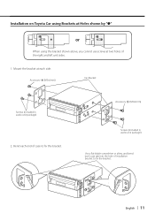
Bend each side. Mount the bracket at two holes of the right and left unit sides. 1. Accessory 0 (M5x6mm) Screws (included in audio unit package) 2. Installation on Toyota Car using Brackets at Holes shown by "●" or When using the bracket shown above, you cannot use screws at each end of case to fix the bracket. English | 11 Accessory 0 (M5x6mm) Car Bracket Screws (included in audio unit package) Use a flat-blade screwdriver or pliers, and bend each case tab into the hole of installation bracket to fix the bracket.
Bend each side. Mount the bracket at two holes of the right and left unit sides. 1. Accessory 0 (M5x6mm) Screws (included in audio unit package) 2. Installation on Toyota Car using Brackets at Holes shown by "●" or When using the bracket shown above, you cannot use screws at each end of case to fix the bracket. English | 11 Accessory 0 (M5x6mm) Car Bracket Screws (included in audio unit package) Use a flat-blade screwdriver or pliers, and bend each case tab into the hole of installation bracket to fix the bracket.


