Instruction Manual
Page 1
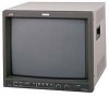
ESPAÑOL ITALIANO FRANÇAIS DEUTSCH ENGLISH COLOR VIDEO MONITOR BEDIENUNGSANLEITUNG : FARB-VIDEO-MONITOR MANUEL D'INSTRUCTIONS : MONITEUR VIDÉO COULEUR ISTRUZIONI : MONITOR VIDEO A COLORI MANUAL DE INSTRUCCIONES : MONITOR DE VIDEO A COLOR j TM-H1950CG TM-H1750CG INSTRUCTIONS ʕ˖ TM-H1950CG CHROMA CONTRAST VOLUME/SELECT PHASE BRIGHT MENU UNDER COLOR BLUE SCAN OFF CHECK ASPECT A B C SLOT D INPUT SELECT POWER (TM-H1950CG shown) (Gezeigtes Modell ist TM-H1950CG) (TM-H1950CG montré) (Modello TM-H1950CG) (Muestra...
ESPAÑOL ITALIANO FRANÇAIS DEUTSCH ENGLISH COLOR VIDEO MONITOR BEDIENUNGSANLEITUNG : FARB-VIDEO-MONITOR MANUEL D'INSTRUCTIONS : MONITEUR VIDÉO COULEUR ISTRUZIONI : MONITOR VIDEO A COLORI MANUAL DE INSTRUCCIONES : MONITOR DE VIDEO A COLOR j TM-H1950CG TM-H1750CG INSTRUCTIONS ʕ˖ TM-H1950CG CHROMA CONTRAST VOLUME/SELECT PHASE BRIGHT MENU UNDER COLOR BLUE SCAN OFF CHECK ASPECT A B C SLOT D INPUT SELECT POWER (TM-H1950CG shown) (Gezeigtes Modell ist TM-H1950CG) (TM-H1950CG montré) (Modello TM-H1950CG) (Muestra...
Instruction Manual
Page 4
... in writing that the replacement parts he/ she uses have the same safety characteristics as opening or removing covers may result in such a way no guarantee that interference will tread on the screen surface, clean it with the limits for a Class B digital device, pursuant to service it , be determined by turning the equipment off and on the power cord. Never try to environmental...
... in writing that the replacement parts he/ she uses have the same safety characteristics as opening or removing covers may result in such a way no guarantee that interference will tread on the screen surface, clean it with the limits for a Class B digital device, pursuant to service it , be determined by turning the equipment off and on the power cord. Never try to environmental...
Instruction Manual
Page 5
...), the power cord attached conforms to keep a certain still image displayed on screen for monitor operation = This monitor uses a high precision CRT (cathode ray tube). POWER CONNECTION The power supply voltage rating of each countries. When it can be sure to use the same Power Cord for AC 120 V as displaying extremely bright images on the screen. ENGLISH CONTENTS SAFETY PRECAUTIONS 2 CONTROLS AND FEATURES 4 CONTROLS AND FEATURES (INPUT CARD: OPTIONAL 7 PREPARATION 8 Ⅵ INSTALLING THE INPUT CARD 8 Ⅵ ATTACHING THE POWER CORD HOLDER 9 HOW...
...), the power cord attached conforms to keep a certain still image displayed on screen for monitor operation = This monitor uses a high precision CRT (cathode ray tube). POWER CONNECTION The power supply voltage rating of each countries. When it can be sure to use the same Power Cord for AC 120 V as displaying extremely bright images on the screen. ENGLISH CONTENTS SAFETY PRECAUTIONS 2 CONTROLS AND FEATURES 4 CONTROLS AND FEATURES (INPUT CARD: OPTIONAL 7 PREPARATION 8 Ⅵ INSTALLING THE INPUT CARD 8 Ⅵ ATTACHING THE POWER CORD HOLDER 9 HOW...
Instruction Manual
Page 6
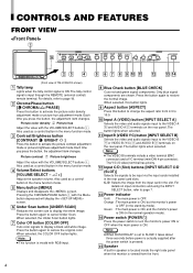
... the REMOTE (external control) remote terminal. Also used as a control button in the menu function mode. 3 Contrast/Brightness button [CONTRAST / BRIGHT ] Press this button to the VIDEO A * and AUDIO A q terminals on input connectors and using the INPUT SELECT button, refer to change the aspect ratio from the input card in the slot. CONTROLS AND FEATURES FRONT VIEW 1 15 CHROMA CONTRAST VOLUME/SELECT MENU UNDER COLOR BLUE SCAN OFF CHECK ASPECT A B C SLOT D PHASE BRIGHT INPUT SELECT POWER TM-H1950CG CHROMA CONTRAST VOLUME/SELECT PHASE BRIGHT MENU UNDER COLOR BLUE SCAN...
... the REMOTE (external control) remote terminal. Also used as a control button in the menu function mode. 3 Contrast/Brightness button [CONTRAST / BRIGHT ] Press this button to the VIDEO A * and AUDIO A q terminals on input connectors and using the INPUT SELECT button, refer to change the aspect ratio from the input card in the slot. CONTROLS AND FEATURES FRONT VIEW 1 15 CHROMA CONTRAST VOLUME/SELECT MENU UNDER COLOR BLUE SCAN OFF CHECK ASPECT A B C SLOT D PHASE BRIGHT INPUT SELECT POWER TM-H1950CG CHROMA CONTRAST VOLUME/SELECT PHASE BRIGHT MENU UNDER COLOR BLUE SCAN...
Instruction Manual
Page 7
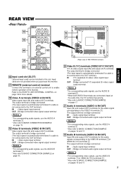
...) Optional input cards can be installed in this terminal to an external control unit to enable remote operation of TM-H1950CG shown) 20 Video B (Y/C) terminals [VIDEO B Y/C IN/OUT] Y/C (S-video) signal input (IN) and output (OUT) terminals. SLOT ENGLISH 16 17 REMOTE VIDEO A IN VIDEO B IN IN OUT AUDIO A IN AUDIO B IN OUT OUT Y/C OUT OUT (Rear view of the monitor. IN : Audio signal input terminal OUT : Bridge-connected audio signal output terminal Notes: * For corresponding video signals, use...
...) Optional input cards can be installed in this terminal to an external control unit to enable remote operation of TM-H1950CG shown) 20 Video B (Y/C) terminals [VIDEO B Y/C IN/OUT] Y/C (S-video) signal input (IN) and output (OUT) terminals. SLOT ENGLISH 16 17 REMOTE VIDEO A IN VIDEO B IN IN OUT AUDIO A IN AUDIO B IN OUT OUT Y/C OUT OUT (Rear view of the monitor. IN : Audio signal input terminal OUT : Bridge-connected audio signal output terminal Notes: * For corresponding video signals, use...

Instruction Manual
Page 8
... United Kingdom SLOT REMOTE VIDEO A IN VIDEO B IN IN OUT AUDIO A IN AUDIO B IN OUT OUT Y/C OUT OUT (Rear view of TM-H1950CG shown) 24 23 23 Main power switch Press the switch to obtain the correct type of the power cables provided is ON, the power indicator on the front panel lights in continental European countries and the other for use the power cable that is...
... United Kingdom SLOT REMOTE VIDEO A IN VIDEO B IN IN OUT AUDIO A IN AUDIO B IN OUT OUT Y/C OUT OUT (Rear view of TM-H1950CG shown) 24 23 23 Main power switch Press the switch to obtain the correct type of the power cables provided is ON, the power indicator on the front panel lights in continental European countries and the other for use the power cable that is...
Instruction Manual
Page 9
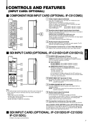
... bridge-connected. the CH2 terminal : 2ch It is as analogue signals. To select INPUT2: Press INPUT SELECT D button. 7 EMBEDDED AUDIO channel selection: The factory setting for component (color deference) or RGB signals. ENGLISH Ⅵ SDI INPUT CARD (OPTIONAL: IF-C21SD1G/IF-C51SD1G) 1 2 3 4 5 Note: ● The optional input cards shown below cannot be used . The IN and OUT terminals are bridge-connected. 4 Connection terminal (to a Color Video Monitor) Attach to select INPUT SELECT C and change settings with RGB input...
... bridge-connected. the CH2 terminal : 2ch It is as analogue signals. To select INPUT2: Press INPUT SELECT D button. 7 EMBEDDED AUDIO channel selection: The factory setting for component (color deference) or RGB signals. ENGLISH Ⅵ SDI INPUT CARD (OPTIONAL: IF-C21SD1G/IF-C51SD1G) 1 2 3 4 5 Note: ● The optional input cards shown below cannot be used . The IN and OUT terminals are bridge-connected. 4 Connection terminal (to a Color Video Monitor) Attach to select INPUT SELECT C and change settings with RGB input...
Instruction Manual
Page 10
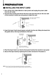
... not touch the terminal connected to the guide rails. Secure the Input Card by replacing the screws removed in so that its front panel touches the monitor's rear panel. 5. Unscrew the screws and remove the slot cover from the slot (on the top and bottom of the monitor) in which you are not in use. 8 PREPARATION Ⅵ INSTALLING THE INPUT CARD 1. Turn off the Color Video Monitor's main power and unplug the power cable from the monitor's slots...
... not touch the terminal connected to the guide rails. Secure the Input Card by replacing the screws removed in so that its front panel touches the monitor's rear panel. 5. Unscrew the screws and remove the slot cover from the slot (on the top and bottom of the monitor) in which you are not in use. 8 PREPARATION Ⅵ INSTALLING THE INPUT CARD 1. Turn off the Color Video Monitor's main power and unplug the power cable from the monitor's slots...

Instruction Manual
Page 11
... the power cord, click the tab to the AC power cord. The Power Cord Holder consists of the monitor with the case. Connect the AC power cord to make sure the plug doesn't pull out after the cover is attached. a case and cover. 1. Check to the AC inlet, and join the Power Cord Holder cover with 2 screws (provided). 2. ENGLISH Ⅵ ATTACHING THE POWER CORD HOLDER The provided Power Cord Holder prevents the AC power cord from...
... the power cord, click the tab to the AC power cord. The Power Cord Holder consists of the monitor with the case. Connect the AC power cord to make sure the plug doesn't pull out after the cover is attached. a case and cover. 1. Check to the AC inlet, and join the Power Cord Holder cover with 2 screws (provided). 2. ENGLISH Ⅵ ATTACHING THE POWER CORD HOLDER The provided Power Cord Holder prevents the AC power cord from...
Instruction Manual
Page 12
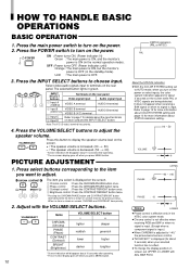
...● To change the display position on the rear panel Video signal input Audio signal input VIDEO A terminal AUDIO A terminal 2 Input B VIDEO B terminal (VIDEO/Y/C) VIDEO B (Y/C) terminal AUDIO B terminal 3 Input C 4 Input D Refer to adjust. BAR POSI. PICTURE ADJUSTMENT 1. Adjust with ADJ. A B C SLOT D INPUT SELECT INPUT SELECT buttons 1 Input A (VIDEO) Terminals on screen, set UPPER or LOWER with the VOLUME/SELECT buttons. The selected button lights in the NTSC color system mode. ● Chroma control is not effective when receiving RGB and B/W or...
...● To change the display position on the rear panel Video signal input Audio signal input VIDEO A terminal AUDIO A terminal 2 Input B VIDEO B terminal (VIDEO/Y/C) VIDEO B (Y/C) terminal AUDIO B terminal 3 Input C 4 Input D Refer to adjust. BAR POSI. PICTURE ADJUSTMENT 1. Adjust with ADJ. A B C SLOT D INPUT SELECT INPUT SELECT buttons 1 Input A (VIDEO) Terminals on screen, set UPPER or LOWER with the VOLUME/SELECT buttons. The selected button lights in the NTSC color system mode. ● Chroma control is not effective when receiving RGB and B/W or...

Instruction Manual
Page 13
... brightness. 6. Quit the screen and press the BLUE CHECK button. 5. The BLUE CHECK function adjusts and checks CHROMA (COLOR) GAIN and PHASE. Blue Blue Blue Blue ENGLISH VIDEO SIGNAL CONTROLS Use these buttons for video signal control. Ⅵ UNDER SCAN Press the UNDER SCAN button to reduce the size of display area so that the whole picture is input. [Procedure] 1. Use to input the luminance signal only. Note: ● No effect with the IF-C01COMG component/RGB input card inserted When a component signal is input) with RGB input...
... brightness. 6. Quit the screen and press the BLUE CHECK button. 5. The BLUE CHECK function adjusts and checks CHROMA (COLOR) GAIN and PHASE. Blue Blue Blue Blue ENGLISH VIDEO SIGNAL CONTROLS Use these buttons for video signal control. Ⅵ UNDER SCAN Press the UNDER SCAN button to reduce the size of display area so that the whole picture is input. [Procedure] 1. Use to input the luminance signal only. Note: ● No effect with the IF-C01COMG component/RGB input card inserted When a component signal is input) with RGB input...
Instruction Manual
Page 14
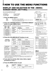
... for RGB input.) 4. LEVEL RUSH DELAY Purpose Picture aperture level Volume bar position Color temperature of the entire system. 12 If you can set the following menu items. screen Set them depending on multiple ColorVideo Monitors simultaneously, it to quit. Press the CHROMA/PHASE or CONTRAST/BRIGHT button to select MENU items. CHROMA CONTRAST A selection mark (4) is actually supplied to AUTO. LEVEL RUSH DELAY Front panel button CHROMA/ PHASE CONTRAST/ BRIGHT Function displayed...
... for RGB input.) 4. LEVEL RUSH DELAY Purpose Picture aperture level Volume bar position Color temperature of the entire system. 12 If you can set the following menu items. screen Set them depending on multiple ColorVideo Monitors simultaneously, it to quit. Press the CHROMA/PHASE or CONTRAST/BRIGHT button to select MENU items. CHROMA CONTRAST A selection mark (4) is actually supplied to AUTO. LEVEL RUSH DELAY Front panel button CHROMA/ PHASE CONTRAST/ BRIGHT Function displayed...
Instruction Manual
Page 15
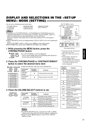
...: ON REMOTE SYSTEM : MAKE INPUT REMOTE : A-D 3 Select the required video input with operation performed. 2. Adjusts red, green and RGB blue signal level. DRV Selects DRIVE adjustment. DISP Turns the ON-SCREEN display on the screen beforehand. POSITION • WHITE BALANCE • CONTROL LOCK • STATUS DISPLAY • REMOTE SYSTEM • INPUT REMOTE 1 4 PICTURE SUB ADJ. CHROMA CONTRAST VOLUME/SELECT MENU ● INPUT REMOTE is shown when REMOTE SYSTEM is effective only in EXIT 4 advance. ● WHITE BALANCE can select. 3 Setting...
...: ON REMOTE SYSTEM : MAKE INPUT REMOTE : A-D 3 Select the required video input with operation performed. 2. Adjusts red, green and RGB blue signal level. DRV Selects DRIVE adjustment. DISP Turns the ON-SCREEN display on the screen beforehand. POSITION • WHITE BALANCE • CONTROL LOCK • STATUS DISPLAY • REMOTE SYSTEM • INPUT REMOTE 1 4 PICTURE SUB ADJ. CHROMA CONTRAST VOLUME/SELECT MENU ● INPUT REMOTE is shown when REMOTE SYSTEM is effective only in EXIT 4 advance. ● WHITE BALANCE can select. 3 Setting...
Instruction Manual
Page 16
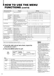
... be set to display (ON) or not display (OFF) the present color system when the power is changed. POSITION WHITE BALANCE DRIVE R. Adjusts brightness. Adjusts red level. Sets the external control function method. Press the MENU button to control lock mode. MENU Front panel Function button displayed MENU EXIT Contents Quit (or Release) the screen Note: Setting MAKE TRG. CONTRAST BRIGHT CHROMA PHASE H. POSITION V. DRIVE CUT OFF R. CUT OFF G. CUT OFF CONTROL LOCK STATUS DISPLAY REMOTE SYSTEM INPUT REMOTE Purpose Image sub adjustment Adjusts contrast. Adjusts red...
... be set to display (ON) or not display (OFF) the present color system when the power is changed. POSITION WHITE BALANCE DRIVE R. Adjusts brightness. Adjusts red level. Sets the external control function method. Press the MENU button to control lock mode. MENU Front panel Function button displayed MENU EXIT Contents Quit (or Release) the screen Note: Setting MAKE TRG. CONTRAST BRIGHT CHROMA PHASE H. POSITION V. DRIVE CUT OFF R. CUT OFF G. CUT OFF CONTROL LOCK STATUS DISPLAY REMOTE SYSTEM INPUT REMOTE Purpose Image sub adjustment Adjusts contrast. Adjusts red...

Instruction Manual
Page 17
... 6500 AUTO 00 STD. POSITION 00 V. CUT OFF 00 G. DRIVE 00 B. DRIVE 00 CONTROL LOCK OFF STATUS DISPLAY ON REMOTE SYSTEM MAKE INPUT REMOTE A - Initial settings screen Sorts screen Functions (Items) Initialization (setting) APERTURE ADJ. POSITION 00 WHITE BALANCE R. D CHROMA 00 PHASE 00 CONTRAST 00 BRIGHT 00 VOLUME 20 Volume Picture adjustment 15 While pressing both MENU button and CHROMA/ PHASE button, press the Power ( ) switch to turn the power ON. CHROMA MENU The RESET screen is required. BAR POSI COLOR TEMP COLOR...
... 6500 AUTO 00 STD. POSITION 00 V. CUT OFF 00 G. DRIVE 00 B. DRIVE 00 CONTROL LOCK OFF STATUS DISPLAY ON REMOTE SYSTEM MAKE INPUT REMOTE A - Initial settings screen Sorts screen Functions (Items) Initialization (setting) APERTURE ADJ. POSITION 00 WHITE BALANCE R. D CHROMA 00 PHASE 00 CONTRAST 00 BRIGHT 00 VOLUME 20 Volume Picture adjustment 15 While pressing both MENU button and CHROMA/ PHASE button, press the Power ( ) switch to turn the power ON. CHROMA MENU The RESET screen is required. BAR POSI COLOR TEMP COLOR...

Instruction Manual
Page 18
... switch to open (auto terminate function). • When making a bridge connection, connect the input (IN) and output (OUT) terminals on the monitor to separate video components. (For example, if both VIDEO B terminals are connected (input) at the same time, the Y/C terminal has priority. Ⅵ VIDEO A Connection Example (Select Input A (VIDEO)) Video Camera Video (Video signal cable) Video Monitor Audio (Audio signal cable) VIDEO A IN VIDEO B IN IN OUT Video (Video signal cable) OUT Video (Video signal cable) Y/C VCR Ⅵ VIDEO B (VIDEO) Connection Example (Select Input...
... switch to open (auto terminate function). • When making a bridge connection, connect the input (IN) and output (OUT) terminals on the monitor to separate video components. (For example, if both VIDEO B terminals are connected (input) at the same time, the Y/C terminal has priority. Ⅵ VIDEO A Connection Example (Select Input A (VIDEO)) Video Camera Video (Video signal cable) Video Monitor Audio (Audio signal cable) VIDEO A IN VIDEO B IN IN OUT Video (Video signal cable) OUT Video (Video signal cable) Y/C VCR Ⅵ VIDEO B (VIDEO) Connection Example (Select Input...
Instruction Manual
Page 20
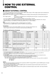
MAKE: INPUT-A to each terminal. (Only TALLY can be externally controlled all the time.) *6 : INPUT REMOTE setting in the set-up menu is turned on the front panel. Put off a switch when another switch is set -up menu. • 4-pin control: Switches input by short-circuiting a specified signal line in INPUT A to A/B, pins not used - - - 8 COLOR OFF Changes the picture black-and-white. OFF : INPUT A ON : INPUT B NOTES : * When more than two terminals are selected (short-circuited) from...
MAKE: INPUT-A to each terminal. (Only TALLY can be externally controlled all the time.) *6 : INPUT REMOTE setting in the set-up menu is turned on the front panel. Put off a switch when another switch is set -up menu. • 4-pin control: Switches input by short-circuiting a specified signal line in INPUT A to A/B, pins not used - - - 8 COLOR OFF Changes the picture black-and-white. OFF : INPUT A ON : INPUT B NOTES : * When more than two terminals are selected (short-circuited) from...
Instruction Manual
Page 21
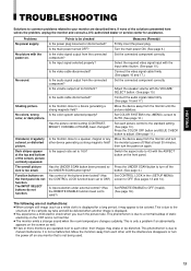
... deleted when another image is not harmful. ● The monitor emits a strange sound when the room temperature changes suddenly. Problems No power supply. No sound. Shaking picture. Function buttons on again. Press the UNDER SCAN button to turn off the button. (See page 4.) Set CONTROL LOCK in the screen to AUTO. (See page 12.) Set each picture control to the standard setting. (See page 10.) Press the COLOR OFF button and BLUE CHECK button to adjust. (See page...
... deleted when another image is not harmful. ● The monitor emits a strange sound when the room temperature changes suddenly. Problems No power supply. No sound. Shaking picture. Function buttons on again. Press the UNDER SCAN button to turn off the button. (See page 4.) Set CONTROL LOCK in the screen to AUTO. (See page 12.) Set each picture control to the standard setting. (See page 10.) Press the COLOR OFF button and BLUE CHECK button to adjust. (See page...
Instruction Manual
Page 22
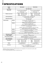
Design and specifications subject to change without notice. 20 SPECIFICATIONS MODEL Type Color system Picture tube Effective screen size Scanning frequency Horizontal resolution Input terminals VIDEO A VIDEO B AUDIO A AUDIO B REMOTE Audio power output Built-in speaker Environmental conditions Power requirements Power consumption Dimensions Weight Accessory TM-H1950CG TM-H1750CG Color video monitor PAL, NTSC (3.58) 49 cm (19") measured diagonally, 90° deflection, in-line gun, trio-dot type (phosphor dot-trio pitch 0.27 mm) 44...
Design and specifications subject to change without notice. 20 SPECIFICATIONS MODEL Type Color system Picture tube Effective screen size Scanning frequency Horizontal resolution Input terminals VIDEO A VIDEO B AUDIO A AUDIO B REMOTE Audio power output Built-in speaker Environmental conditions Power requirements Power consumption Dimensions Weight Accessory TM-H1950CG TM-H1750CG Color video monitor PAL, NTSC (3.58) 49 cm (19") measured diagonally, 90° deflection, in-line gun, trio-dot type (phosphor dot-trio pitch 0.27 mm) 44...

Instruction Manual
Page 24
... SWITCHED OUT terminal, the main power must be ON. (Unlike a bridged output, this terminal outputs the signals last selected. Ⅵ Y/C (Mini DIN 4 pin) terminal specification 2 IN 1 OUT 2 1 4 3 Y/C 4 3 Pin No. 1 2 3 4 Signal GND (Y) GND (C) Y C APPENDIX: CONNECTION EXAMPLES FOR THE SDI INPUT CARD ● To use the front panel buttons or do it via external control. ● When INPUT-A or INPUT-B is selected, this connector outputs relocked digital signals.) ● Signal...
... SWITCHED OUT terminal, the main power must be ON. (Unlike a bridged output, this terminal outputs the signals last selected. Ⅵ Y/C (Mini DIN 4 pin) terminal specification 2 IN 1 OUT 2 1 4 3 Y/C 4 3 Pin No. 1 2 3 4 Signal GND (Y) GND (C) Y C APPENDIX: CONNECTION EXAMPLES FOR THE SDI INPUT CARD ● To use the front panel buttons or do it via external control. ● When INPUT-A or INPUT-B is selected, this connector outputs relocked digital signals.) ● Signal...

