
Instructions
Page 2
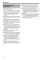
...; Handling camera Note: ● When mounting the base to the ceiling, or when connecting the cable of the camera unit, pay enough attention to the fall prevention wire to carry out reinforcement of each part. When mounting to an insecure location, make sure to prevent this unit from falling accidentally. Mounting the fall prevention wire Connect the fall of the ceiling or wall before installation. Safety...
...; Handling camera Note: ● When mounting the base to the ceiling, or when connecting the cable of the camera unit, pay enough attention to the fall prevention wire to carry out reinforcement of each part. When mounting to an insecure location, make sure to prevent this unit from falling accidentally. Mounting the fall prevention wire Connect the fall of the ceiling or wall before installation. Safety...

Instructions
Page 4
... Precautions for proper installation (continued) Precautions regarding water-proof and dust-proof (continued) Ⅵ Precautions when mounting the dome cover ● Make sure that the fall prevention wire of the dome cover is not caught in the space between the dome cover and base. Otherwise, the ...humidity level may rise, which may cause the dust-proof and waterproof features to malfunction. Ⅵ Binding the sealing tape. (When mounting the camera using the pipe)...
... Precautions for proper installation (continued) Precautions regarding water-proof and dust-proof (continued) Ⅵ Precautions when mounting the dome cover ● Make sure that the fall prevention wire of the dome cover is not caught in the space between the dome cover and base. Otherwise, the ...humidity level may rise, which may cause the dust-proof and waterproof features to malfunction. Ⅵ Binding the sealing tape. (When mounting the camera using the pipe)...

Instructions
Page 7
... equipment and receiver. ● Connect the equipment into an outlet on a circuit different from that interference will not occur in accordance with the limits for help. Ⅵ CAUTION CHANGES OR MODIFICATIONS NOT APPROVED BY JVC COULD VOID USER'S AUTHORITY TO OPERATE THE EQUIPMENT. These limits are designed to Part 15 of Japan Limited.is in a residential installation. Dear Customer...
... equipment and receiver. ● Connect the equipment into an outlet on a circuit different from that interference will not occur in accordance with the limits for help. Ⅵ CAUTION CHANGES OR MODIFICATIONS NOT APPROVED BY JVC COULD VOID USER'S AUTHORITY TO OPERATE THE EQUIPMENT. These limits are designed to Part 15 of Japan Limited.is in a residential installation. Dear Customer...
Instructions
Page 8
...), Isolated power supply only (For Europe). ⅷ This installation should be made by UL to be used for Burglar Alarm Functionality. ⅷ When mounting this unit. When mounting to an insecure location, make sure to touch the metal surface of the [MONITOR] terminal to a secure location where it can support the mass of Alarm inputs have not been evaluated by a qualified service person...
...), Isolated power supply only (For Europe). ⅷ This installation should be made by UL to be used for Burglar Alarm Functionality. ⅷ When mounting this unit. When mounting to an insecure location, make sure to touch the metal surface of the [MONITOR] terminal to a secure location where it can support the mass of Alarm inputs have not been evaluated by a qualified service person...
Instructions
Page 9
... overload wall outlets and extension cords as this can result in installation such as the original part. Do not place this appliance on the power cord. An appliance and cart combination should never be sure the service technician has used replacement parts specified by a qualified technician to restore the appliance to normal operation. Slots and openings in the operating instructions should be operated...
... overload wall outlets and extension cords as this can result in installation such as the original part. Do not place this appliance on the power cord. An appliance and cart combination should never be sure the service technician has used replacement parts specified by a qualified technician to restore the appliance to normal operation. Slots and openings in the operating instructions should be operated...
Instructions
Page 10
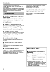
... instructions are for: TK-C215VP4U/TKC215VP4E.) Before beginning to operate this document are the trademarks or registered trademarks of 3 axis rotation mechanism. Ⅵ Non Camera-Like Design Dome-type design allows application in various locations. Ⅵ High Magnification Varifocal/Zoom Lens The built-in x3.6 varifocal lens enables detailed supervision. Ⅵ Easy DAY & NIGHT Feature A Easy DAY & NIGHT feature is available, which switches...
... instructions are for: TK-C215VP4U/TKC215VP4E.) Before beginning to operate this document are the trademarks or registered trademarks of 3 axis rotation mechanism. Ⅵ Non Camera-Like Design Dome-type design allows application in various locations. Ⅵ High Magnification Varifocal/Zoom Lens The built-in x3.6 varifocal lens enables detailed supervision. Ⅵ Easy DAY & NIGHT Feature A Easy DAY & NIGHT feature is available, which switches...

Instructions
Page 11
... Parts 9 Camera 9 Camera (Interior 11 Setting the Lens and Switches 12 Installation and Connection System Example 14 About Connection Cables 15 Video signal cables 15 DC 12 V or AC 24 V power supply cable 15 Procedures from Connection to Setting ..... 16 Setting the switches 17 Mounting the base 17 Cable Connection 19 Mounting the camera unit 20 Adjusting the video image 22 Mounting the test monitor 22 Adjusting the shooting direction of the camera 22 Adjusting the angle of view, focus and brightness 23 Mounting the inner dome 24 Mounting...
... Parts 9 Camera 9 Camera (Interior 11 Setting the Lens and Switches 12 Installation and Connection System Example 14 About Connection Cables 15 Video signal cables 15 DC 12 V or AC 24 V power supply cable 15 Procedures from Connection to Setting ..... 16 Setting the switches 17 Mounting the base 17 Cable Connection 19 Mounting the camera unit 20 Adjusting the video image 22 Mounting the test monitor 22 Adjusting the shooting direction of the camera 22 Adjusting the angle of view, focus and brightness 23 Mounting the inner dome 24 Mounting...

Instructions
Page 12
.... When switching between colored and black-and-white images, the bright portions of the screen are due to the characteristics of the CCD and not malfunctions. ⅷ Turning "ON" the simple DAY & NIGHT switch switches the image to insert the supplied silica gel into a neutral detergent diluted with water, followed by wiping with a dry cloth. For tough stains, wipe using this unit at a wide...
.... When switching between colored and black-and-white images, the bright portions of the screen are due to the characteristics of the CCD and not malfunctions. ⅷ Turning "ON" the simple DAY & NIGHT switch switches the image to insert the supplied silica gel into a neutral detergent diluted with water, followed by wiping with a dry cloth. For tough stains, wipe using this unit at a wide...
Instructions
Page 13
... which this plug when mounting directly to pipes from falling accidentally. The plug for Piping Hole and Piping Hole (Side) Use this product is purchased or any nearby JVC dealer. Name of view before mounting the camera. (A Pg. 17) F Plug for piping hole is not supplied with this product.) Note: ● Connect the fall prevention wire to prevent this hole by default. (A Pg...
... which this plug when mounting directly to pipes from falling accidentally. The plug for Piping Hole and Piping Hole (Side) Use this product is purchased or any nearby JVC dealer. Name of view before mounting the camera. (A Pg. 17) F Plug for piping hole is not supplied with this product.) Note: ● Connect the fall prevention wire to prevent this hole by default. (A Pg...

Instructions
Page 15
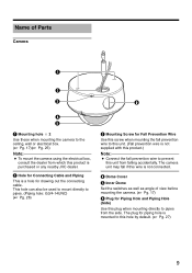
...) P [MONITOR]Monitor Terminal (Pin Jack) (A Pg. 22) Q Camera R Connector for Power Supply of the image. (A Pg. 22) M Rotation Center Mark (A Pg. 22) N Fall Prevention Wire Use this to fasten the camera unit Q to the base G. Camera (Interior) L M N O P Q Lens (A next page) X W V U R S L Rotation Knob Rotate the lens unit to adjust the inclination of Heater This is a power connector for use when the heater (sold separately: KA-ZH215) is mounted. S Space for Heater T Camera Unit Fastening...
...) P [MONITOR]Monitor Terminal (Pin Jack) (A Pg. 22) Q Camera R Connector for Power Supply of the image. (A Pg. 22) M Rotation Center Mark (A Pg. 22) N Fall Prevention Wire Use this to fasten the camera unit Q to the base G. Camera (Interior) L M N O P Q Lens (A next page) X W V U R S L Rotation Knob Rotate the lens unit to adjust the inclination of Heater This is a power connector for use when the heater (sold separately: KA-ZH215) is mounted. S Space for Heater T Camera Unit Fastening...
Instructions
Page 16
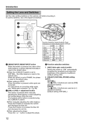
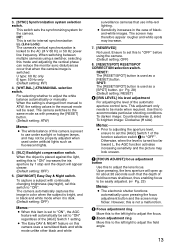
.... For instructions on the camera unit before mounting it. The function of this button is selected using the 2 [SELECT] switch. ● When manually adjusting the white balance: Press the R button to adjust the phase. To set to WHT.BAL., the white balance is reset to SPOT: When this button is pressed, white spots are used as [+/-] adjustment buttons. (Default setting: WHT.BAL.) 12 C Function selection switches 1. [AGC] Auto-gain control switch. When the switch is set to PHASE...
.... For instructions on the camera unit before mounting it. The function of this button is selected using the 2 [SELECT] switch. ● When manually adjusting the white balance: Press the R button to adjust the phase. To set to WHT.BAL., the white balance is reset to SPOT: When this button is pressed, white spots are used as [+/-] adjustment buttons. (Default setting: WHT.BAL.) 12 C Function selection switches 1. [AGC] Auto-gain control switch. When the switch is set to PHASE...
Instructions
Page 17
... the focus adjustment button and the screen may look uneven. The camera switches to AONB. The camera automatically captures the image in color when the subject is bright, and in the manual mode will open up for the camera. U type: 60 Hz only E type: 50 Hz only (Default setting: INT) 4. [WHT.BAL.] ATW/MANUAL selection switch. The screen may therefore appear rougher and white spots may not be reset...
... the focus adjustment button and the screen may look uneven. The camera switches to AONB. The camera automatically captures the image in color when the subject is bright, and in the manual mode will open up for the camera. U type: 60 Hz only E type: 50 Hz only (Default setting: INT) 4. [WHT.BAL.] ATW/MANUAL selection switch. The screen may therefore appear rougher and white spots may not be reset...
Instructions
Page 18
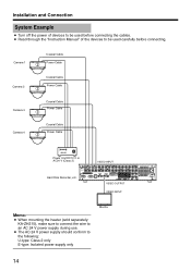
... COM ALARM OUT OUT OUT 9 12 13 16 EE OUT VIDEO OUTPUT VIDEO INPUT AC IN (220V-240V ) SIGNAL GND Memo: ● When mounting the heater (sold separately: KA-ZH215), make sure to connect the wire to an AC 24 V power supply during use. ● The AC 24 V power supply should conform to be used carefully before connecting. Installation and Connection System Example ● Turn off the power...
... COM ALARM OUT OUT OUT 9 12 13 16 EE OUT VIDEO OUTPUT VIDEO INPUT AC IN (220V-240V ) SIGNAL GND Memo: ● When mounting the heater (sold separately: KA-ZH215), make sure to connect the wire to an AC 24 V power supply during use. ● The AC 24 V power supply should conform to be used carefully before connecting. Installation and Connection System Example ● Turn off the power...
Instructions
Page 20
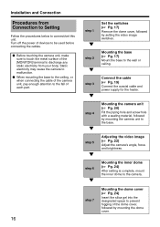
..., or when connecting the cable of the camera unit, pay enough attention to the fall of each part. 16 step 1 K step 2 K step 3 K step 4 K step 5 K step 6 K step 7 Set the switches (A Pg. 17) Remove the dome cover, followed by mounting the camera unit to the base. Adjusting the video image (A Pg. 22) Adjust the camera's angle, focus and brightness. Connect the cable (A Pg. 19) Connect the coaxial cable and power supply for the heater. Mounting the camera unit (A Pg...
..., or when connecting the cable of the camera unit, pay enough attention to the fall of each part. 16 step 1 K step 2 K step 3 K step 4 K step 5 K step 6 K step 7 Set the switches (A Pg. 17) Remove the dome cover, followed by mounting the camera unit to the base. Adjusting the video image (A Pg. 22) Adjust the camera's angle, focus and brightness. Connect the cable (A Pg. 19) Connect the coaxial cable and power supply for the heater. Mounting the camera unit (A Pg...
Instructions
Page 21
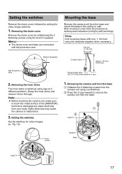
... cause the camera to a wall, follow the procedures by replacing areas indicated as [ceiling] by setting the video image switches. 1. Setup Drill mounting holes (R30 mm, 1 1/8 inch) using a screwdriver. Grasp the inner dome and remove it from the base. B Press the 2 lugs inwards to the ceiling or wall. Memo: ● The dome cover and base are connected with fall prevention wire. When mounting to malfunction. 3. A B Lug(x 2) Camera Inner Dome 2 Base Lug...
... cause the camera to a wall, follow the procedures by replacing areas indicated as [ceiling] by setting the video image switches. 1. Setup Drill mounting holes (R30 mm, 1 1/8 inch) using a screwdriver. Grasp the inner dome and remove it from the base. B Press the 2 lugs inwards to the ceiling or wall. Memo: ● The dome cover and base are connected with fall prevention wire. When mounting to malfunction. 3. A B Lug(x 2) Camera Inner Dome 2 Base Lug...

Instructions
Page 22
... with this product. Use appropriate type of screw according to the material of the rounded portion on the inner side of the dome cover to come off easily. ● R4 mm screws are not supplied with shooting direction (Face upward when mounting to a firm place using 2 R4 mm mounting screws. Mounting the fall prevention wire. Installation and Connection Mounting the base (continued) 2.
... with this product. Use appropriate type of screw according to the material of the rounded portion on the inner side of the dome cover to come off easily. ● R4 mm screws are not supplied with shooting direction (Face upward when mounting to a firm place using 2 R4 mm mounting screws. Mounting the fall prevention wire. Installation and Connection Mounting the base (continued) 2.
Instructions
Page 23
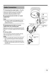
... 12 V Power Supply Wire 4 Cable Storage Space S ] 19 Binding the AC 24 V/DC 12 V power supply wires with insulating tape. 4. Storing cables Upon connecting, push the connector into the electrical box. ● While the camera unit is disconnected from the base, be extremely careful not to an AC 24 V supply during use. 3. Note: ● When mounting the camera to the electrical box, push the connector into the cable storage space of...
... 12 V Power Supply Wire 4 Cable Storage Space S ] 19 Binding the AC 24 V/DC 12 V power supply wires with insulating tape. 4. Storing cables Upon connecting, push the connector into the electrical box. ● While the camera unit is disconnected from the base, be extremely careful not to an AC 24 V supply during use. 3. Note: ● When mounting the camera to the electrical box, push the connector into the cable storage space of...

Instructions
Page 27
... electronic shutter mode is perpendicular to the light axis of view] and [Adjusting the focus] for the zoom adjustment ring and move the ring to the left / right to cover the dome cover over the lens. However, this may cause the lens to go out of focus when the dome cover is mounted. ● When adjusting the focus, cover the dome cover such that the image is...
... electronic shutter mode is perpendicular to the light axis of view] and [Adjusting the focus] for the zoom adjustment ring and move the ring to the left / right to cover the dome cover over the lens. However, this may cause the lens to go out of focus when the dome cover is mounted. ● When adjusting the focus, cover the dome cover such that the image is...

Instructions
Page 29
... box by using the electrical box Mounting the base to the base ● (A Pg. 20) ● Adjusting Images (A Pg. 22) ● Mounting the inner dome (A Pg. 24) ● Mounting the dome cover (A Pg. 24) 25 Removing the camera unit from the base (A Pg. 17) 3. Memo: ● M4 screws are same as normal mounting ● Cable Connection (A Pg. 19) ● Mounting the camera unit to the electrical box. 1. Setting the switches (A Pg...
... box by using the electrical box Mounting the base to the base ● (A Pg. 20) ● Adjusting Images (A Pg. 22) ● Mounting the inner dome (A Pg. 24) ● Mounting the dome cover (A Pg. 24) 25 Removing the camera unit from the base (A Pg. 17) 3. Memo: ● M4 screws are same as normal mounting ● Cable Connection (A Pg. 19) ● Mounting the camera unit to the electrical box. 1. Setting the switches (A Pg...
Instructions
Page 30
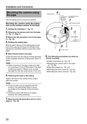
...; Cable Connection (A Pg. 19) ● Mounting the camera unit to do so may damage the internal components of the base 1. Failure to the base (A Pg. 20) ● Adjusting Images (A Pg. 22) ● Mounting the inner dome (A Pg. 24) ● Mounting the dome cover (A Pg. 24) 26 Mounting the fall prevention wire to the joint of the pipe (point where the thread of the pipe). 5. Mounting the camera using...
...; Cable Connection (A Pg. 19) ● Mounting the camera unit to do so may damage the internal components of the base 1. Failure to the base (A Pg. 20) ● Adjusting Images (A Pg. 22) ● Mounting the inner dome (A Pg. 24) ● Mounting the dome cover (A Pg. 24) 26 Mounting the fall prevention wire to the joint of the pipe (point where the thread of the pipe). 5. Mounting the camera using...


