
Instruction Manual
Page 5
... COMMUNICATION Screen 35 FACTORY SETTINGS Screen 35 BLC EDITTING Screen ...36 Manual Adjustment of White Balance 37 CAMERA TITLE Setting ...38 Setting the MOTION DETECT Function 39 Output of Black-White/Color switching signal 40 Control by Black-White/Color switching signal from the outside 41 OTHERS Installing the ferrite core ...42 Specifications ...42 E-5 Thank you for purchasing this product. (These instrustions are for TK-C1460U and TK-C1460E) Before beginning to operate this unit, please read the instruction manual...
... COMMUNICATION Screen 35 FACTORY SETTINGS Screen 35 BLC EDITTING Screen ...36 Manual Adjustment of White Balance 37 CAMERA TITLE Setting ...38 Setting the MOTION DETECT Function 39 Output of Black-White/Color switching signal 40 Control by Black-White/Color switching signal from the outside 41 OTHERS Installing the ferrite core ...42 Specifications ...42 E-5 Thank you for purchasing this product. (These instrustions are for TK-C1460U and TK-C1460E) Before beginning to operate this unit, please read the instruction manual...
Instruction Manual
Page 6
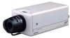
.... INTRODUCTION Features Ⅲ A new DSP (Digital Signal Processor) features a Extended Dynamic Range (ExDR) and enables to shoot both bright and dark locations. Ⅲ The use of a new CCD with diversified systems. Ⅲ Day/Night surveillance When the light is low, the camera pictures can be switched automatically to black and white pictures. Ⅲ Electronic zoom The 10x electronic zoom allows monitoring in far greater detail...
.... INTRODUCTION Features Ⅲ A new DSP (Digital Signal Processor) features a Extended Dynamic Range (ExDR) and enables to shoot both bright and dark locations. Ⅲ The use of a new CCD with diversified systems. Ⅲ Day/Night surveillance When the light is low, the camera pictures can be switched automatically to black and white pictures. Ⅲ Electronic zoom The 10x electronic zoom allows monitoring in far greater detail...

Instruction Manual
Page 7
... lens to the H position (iris open), and then adjust it to the fluctuation of water and a neutral detergent. ● TK-C1460U and TK-C1460E The unit is to take enough time and fix the cable securely. ● When a highly bright subject is shot, sometimes undulations can be sure to use a housing and the like. ● Do not install or use the camera in the following : TK-C1460U...
... lens to the H position (iris open), and then adjust it to the fluctuation of water and a neutral detergent. ● TK-C1460U and TK-C1460E The unit is to take enough time and fix the cable securely. ● When a highly bright subject is shot, sometimes undulations can be sure to use a housing and the like. ● Do not install or use the camera in the following : TK-C1460U...

Instruction Manual
Page 8
... focus adjustment ring Adjusting the back focus during lens installation. When readjustment is required, loosen the locking screw 3 by turning it counterclockwise and turn the back focus adjustment ring 2 . To re-attach the bracket use of the camera before shipment. After the adjustment, tighten the locking screw 3 again. 3 [BF LOCK] Back focus locking screw This serves to prevent any fall when mounting the camera. INTRODUCTION Controls, Connectors and Indicators 2 1 3 4 5 7 6 1 Lens mount...
... focus adjustment ring Adjusting the back focus during lens installation. When readjustment is required, loosen the locking screw 3 by turning it counterclockwise and turn the back focus adjustment ring 2 . To re-attach the bracket use of the camera before shipment. After the adjustment, tighten the locking screw 3 again. 3 [BF LOCK] Back focus locking screw This serves to prevent any fall when mounting the camera. INTRODUCTION Controls, Connectors and Indicators 2 1 3 4 5 7 6 1 Lens mount...

Instruction Manual
Page 9
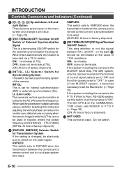
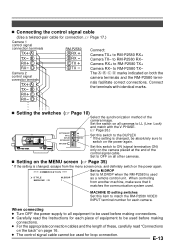
... Selector Switch This is set according to an automatic iris control lens. (੬ Page 15) 11 [MENU] Menu Button When the button is pressed, a menu screen is brought up. (੬ Page 23) 12 [SET/AWC] Set. VIDEO: In case of lens when an automatic iris control lens is used. Auto White Control Button SET: Press this button to make fine adjustments on the set white balance. (੬ Page 22,31,37) E-9 It is also possible to display...
... Selector Switch This is set according to an automatic iris control lens. (੬ Page 15) 11 [MENU] Menu Button When the button is pressed, a menu screen is brought up. (੬ Page 23) 12 [SET/AWC] Set. VIDEO: In case of lens when an automatic iris control lens is used. Auto White Control Button SET: Press this button to make fine adjustments on the set white balance. (੬ Page 22,31,37) E-9 It is also possible to display...
Instruction Manual
Page 10
... back 20 should be used in regions where the power frequency is 60 Hz (50 Hz) ( ):TK-C1460U) (INT/GL: At time of factory shipment) 16 [DUPLEX, SIMPLEX] Selector Switch for the external synchronization input signal. When switching between multiple cameras using a switcher, selecting this mode and adjusting the vertical phase can set a synchronizing system of the camera. DUPLEX: This switch sets to SIMPLEX when the...
... back 20 should be used in regions where the power frequency is 60 Hz (50 Hz) ( ):TK-C1460U) (INT/GL: At time of factory shipment) 16 [DUPLEX, SIMPLEX] Selector Switch for the external synchronization input signal. When switching between multiple cameras using a switcher, selecting this mode and adjusting the vertical phase can set a synchronizing system of the camera. DUPLEX: This switch sets to SIMPLEX when the...
Instruction Manual
Page 11
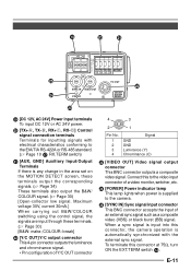
... this connector, the camera operation is any change in the area set on the MOTION DETECT screen, these terminals. (੬ Page 30) [B&W: make; Connect this to the video input connector of a video monitor, switcher, etc. 24 [POWER] Power indicator lamp This lamp lights when power is supplied to the EIA/TIA RS-422A or RS-485 standard. (੬ Page 10 17 RX.TERM switch) 21 [AUX, GND] Auxiliary Input/Output...
... this connector, the camera operation is any change in the area set on the MOTION DETECT screen, these terminals. (੬ Page 30) [B&W: make; Connect this to the video input connector of a video monitor, switcher, etc. 24 [POWER] Power indicator lamp This lamp lights when power is supplied to the EIA/TIA RS-422A or RS-485 standard. (੬ Page 10 17 RX.TERM switch) 21 [AUX, GND] Auxiliary Input/Output...
Instruction Manual
Page 12
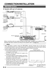
...-1 MONITOR OUTPUT 2 SERIAL-2 MONITOR MONITOR OUTPUT OUTPUT 8 MONITOR MONITOR MONITOR OUTPUT OUTPUT 1 2 O8 UTPUT 1 MONITOR When controlling with up to 16) can be the same as the number of ID-□□ should be connected and used . (੬ Page 14) MEMO • When operating a system using the RM-P2580, several cameras (up to 8 cameras Av Pk L ALC L Camera 1 MACHINE ID:1 (Menu screen) RX TERM: OFF (switch) Av Pk L H ALC LEVEL Camera TK-C1460 Camera TK-C1460 Control signal cable Video signal cable Power cable...
...-1 MONITOR OUTPUT 2 SERIAL-2 MONITOR MONITOR OUTPUT OUTPUT 8 MONITOR MONITOR MONITOR OUTPUT OUTPUT 1 2 O8 UTPUT 1 MONITOR When controlling with up to 16) can be the same as the number of ID-□□ should be connected and used . (੬ Page 14) MEMO • When operating a system using the RM-P2580, several cameras (up to 8 cameras Av Pk L ALC L Camera 1 MACHINE ID:1 (Menu screen) RX TERM: OFF (switch) Av Pk L H ALC LEVEL Camera TK-C1460 Camera TK-C1460 Control signal cable Video signal cable Power cable...
Instruction Manual
Page 13
... the camera image. When connecting ● Turn OFF the power supply to all cameras to the DUPLEX * If the setting is changed , be used before making connections. ● Carefully read "Connections on the back" on the MENU screen (੬ Page 35) * If the setting is changed , escape from another machine, make sure that it matches the communication system used. When controlling from the menu screen once, and definitely switch on the power...
... the camera image. When connecting ● Turn OFF the power supply to all cameras to the DUPLEX * If the setting is changed , be used before making connections. ● Carefully read "Connections on the back" on the MENU screen (੬ Page 35) * If the setting is changed , escape from another machine, make sure that it matches the communication system used. When controlling from the menu screen once, and definitely switch on the power...
Instruction Manual
Page 14
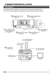
... be used before making carefully. 4.Setting the switches (੬ Page 10) 6.Back focus adjustment (੬ Page 21) Av Pk L H ALC LEVEL SET MENU CAMERA SETUP EXT TERM-OFF INT/GL DUPLEX RX TERM-OFF IOT USED ON LL SIMPLEX ON VIDEO DC 7.Auto white balance control adjustment (੬ Page 22) 5.Lens adjustment (੬ Page 20) 3.Mounting the camera 1.Mounting the lens (੬ Page 18) (੬ Page 15) To controlling systems such as switches Monitor...
... be used before making carefully. 4.Setting the switches (੬ Page 10) 6.Back focus adjustment (੬ Page 21) Av Pk L H ALC LEVEL SET MENU CAMERA SETUP EXT TERM-OFF INT/GL DUPLEX RX TERM-OFF IOT USED ON LL SIMPLEX ON VIDEO DC 7.Auto white balance control adjustment (੬ Page 22) 5.Lens adjustment (੬ Page 20) 3.Mounting the camera 1.Mounting the lens (੬ Page 18) (੬ Page 15) To controlling systems such as switches Monitor...
Instruction Manual
Page 15
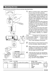
... IRIS VIDEO DC 2. 4. 1. CAUTION: Always attach the fer- Mounting the lens Mount the lens according to be installed as such will not allow normal installation and damage the inner part of plug, use the 4-P plug supplied. To change the mounting method. If the lens has an auto-iris mechanism, 1 rite core (supplied) to 4 the lens cable. 2 (੬ Page 42) connect the lens cable after checking the pin arrangement. BF LOCK (b) F (c) 3. Adjust its position. 24 3. Lens...
... IRIS VIDEO DC 2. 4. 1. CAUTION: Always attach the fer- Mounting the lens Mount the lens according to be installed as such will not allow normal installation and damage the inner part of plug, use the 4-P plug supplied. To change the mounting method. If the lens has an auto-iris mechanism, 1 rite core (supplied) to 4 the lens cable. 2 (੬ Page 42) connect the lens cable after checking the pin arrangement. BF LOCK (b) F (c) 3. Adjust its position. 24 3. Lens...

Instruction Manual
Page 16
.... If voltage drop occurs during operation, the performance will occur when the unit is at the camera side to below 10%, or place the power supply near to the following table shows the connection distances and connection cables provided that the polarities of lug plates for the connections. The following : TK-C1460U Class 2 only TK-C1460E Isolated power supply only E-16 DC12V AC24V CLASS...
.... If voltage drop occurs during operation, the performance will occur when the unit is at the camera side to below 10%, or place the power supply near to the following table shows the connection distances and connection cables provided that the polarities of lug plates for the connections. The following : TK-C1460U Class 2 only TK-C1460E Isolated power supply only E-16 DC12V AC24V CLASS...
Instruction Manual
Page 18
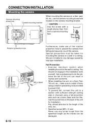
... as a wire chain and the like. We are not liable for any screw longer than 7mm from falling and securely mount the camera. You should not engage in Y/C OUT injuries and accidents. 6mm SYNC IN VIDEO OUT POWER SRMEUAECNTIUNIAOSLNT- M3 x 6mm • When installing the unit on a fixer, Pan/ Tilt unit, etc., make use the camera mounting screw hole located on the camera-mounting bracket. Special precautions...
... as a wire chain and the like. We are not liable for any screw longer than 7mm from falling and securely mount the camera. You should not engage in Y/C OUT injuries and accidents. 6mm SYNC IN VIDEO OUT POWER SRMEUAECNTIUNIAOSLNT- M3 x 6mm • When installing the unit on a fixer, Pan/ Tilt unit, etc., make use the camera mounting screw hole located on the camera-mounting bracket. Special precautions...
Instruction Manual
Page 20
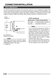
... function of lenses. Make ALC adjustments using the item AVERAGE: PEAK on the monitor, and check the image. CONNECTION/INSTALLATION Lens adjustment Connect the camera according to the connection method, turn it to the optimum level. In such a case, first set to too low a level, malfunction such as follows: (Also read the instruction manual of the lens.) LEVEL adjustment • LEVEL adjustment Monitor screen LEVEL turning direction Too bright Counterclockwise (Toward...
... function of lenses. Make ALC adjustments using the item AVERAGE: PEAK on the monitor, and check the image. CONNECTION/INSTALLATION Lens adjustment Connect the camera according to the connection method, turn it to the optimum level. In such a case, first set to too low a level, malfunction such as follows: (Also read the instruction manual of the lens.) LEVEL adjustment • LEVEL adjustment Monitor screen LEVEL turning direction Too bright Counterclockwise (Toward...

Instruction Manual
Page 21
... position, and adjust the lens focus. 4. Set the lens to ϱ. 4. Loosen the back focus locking screw by turning it clockwise ( ). Loosen the back focus locking screw by turning it clockwise ( ). • With a zoom lens If the image is released. (The ND filter acts to reduce the amount of focus when zooming (telephoto wide-angle), adjust the camera as follows: ● To make back-focus adjustments when changing the lens mounting method or using...
... position, and adjust the lens focus. 4. Set the lens to ϱ. 4. Loosen the back focus locking screw by turning it clockwise ( ). Loosen the back focus locking screw by turning it clockwise ( ). • With a zoom lens If the image is released. (The ND filter acts to reduce the amount of focus when zooming (telephoto wide-angle), adjust the camera as follows: ● To make back-focus adjustments when changing the lens mounting method or using...
Instruction Manual
Page 22
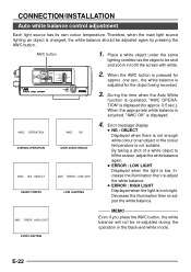
... recorded. 3. Decrease the illumination then re-adjust the white balance. Therefore, when the main light source lighting an object is displayed. AWC ERROR : HIGH LIGHT OVER LIGHTING MEMO Even if you press the AWC button, the white balance will not be adjusted again by pressing the AWC button. CONNECTION/INSTALLATION Auto white balance control adjustment Each light source has its own colour temperature. AWC button 1. During the time when the Auto White function is operated...
... recorded. 3. Decrease the illumination then re-adjust the white balance. Therefore, when the main light source lighting an object is displayed. AWC ERROR : HIGH LIGHT OVER LIGHTING MEMO Even if you press the AWC button, the white balance will not be adjusted again by pressing the AWC button. CONNECTION/INSTALLATION Auto white balance control adjustment Each light source has its own colour temperature. AWC button 1. During the time when the Auto White function is operated...
Instruction Manual
Page 30
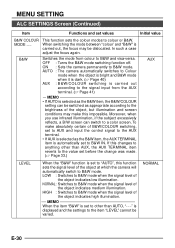
... 40) AUX : B&W/COLOUR switching is displayed and the settings to B&W IN. MEMO When the item "B&W" is set to a color screen. When switching the mode between "colour' and "B&W" is set to other than AUTO, "- - -" is carried out according to the signal input from colour to B&W mode. Moreover, when you use infrared illumination, if the subject excessively reflects, a B/W screen can be switched as appropriate according to...
... 40) AUX : B&W/COLOUR switching is displayed and the settings to B&W IN. MEMO When the item "B&W" is set to a color screen. When switching the mode between "colour' and "B&W" is set to other than AUTO, "- - -" is carried out according to the signal input from colour to B&W mode. Moreover, when you use infrared illumination, if the subject excessively reflects, a B/W screen can be switched as appropriate according to...
Instruction Manual
Page 37
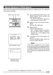
... TK-C1460U. MEMO If the mode is changed , the "+" mark appears at the original position. 4. E-37 MENU button SET button SET AWC MENU CAMERA SETUP V I DE O ADJ U ST WH I T E BAL ANCE COLOUR L EVE L E NHANCE L E V E L P E DEST AL LEVE L AUTO BL AC K CT L AWC NORMAL NORMAL NORMAL OF F VIDEO ADJUST screen WH I T E BALANC E CONT RO L AWC SE T . . Pushing the MENU button returns the screen to blackand-white during the color phase adjustment on the WHITE BALANCE CONTROL screen...
... TK-C1460U. MEMO If the mode is changed , the "+" mark appears at the original position. 4. E-37 MENU button SET button SET AWC MENU CAMERA SETUP V I DE O ADJ U ST WH I T E BAL ANCE COLOUR L EVE L E NHANCE L E V E L P E DEST AL LEVE L AUTO BL AC K CT L AWC NORMAL NORMAL NORMAL OF F VIDEO ADJUST screen WH I T E BALANC E CONT RO L AWC SE T . . Pushing the MENU button returns the screen to blackand-white during the color phase adjustment on the WHITE BALANCE CONTROL screen...
Instruction Manual
Page 41
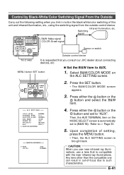
... IN VIDEO OUT POWER Y/C OUT SEE INSTRUCTION MANUAL B&W: Make signal COLOR: Break signal Sensor or switch Outside control device TK-C1460 It is requested that is compatible with the near infrared ray illuminations, use a lens that you link in out-of setting, press the MENU button. • Then, the ALC SETTING screen is automatically set to "AUX". Select B&W/COLOR MODE on the MODE SELECT screen is brought back. Press the SET button. • The B&W/COLOR MODE screen...
... IN VIDEO OUT POWER Y/C OUT SEE INSTRUCTION MANUAL B&W: Make signal COLOR: Break signal Sensor or switch Outside control device TK-C1460 It is requested that is compatible with the near infrared ray illuminations, use a lens that you link in out-of setting, press the MENU button. • Then, the ALC SETTING screen is automatically set to "AUX". Select B&W/COLOR MODE on the MODE SELECT screen is brought back. Press the SET button. • The B&W/COLOR MODE screen...
Instruction Manual
Page 43
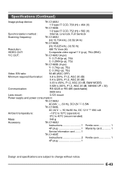
.../s Lens mount: C/CS mount Power supply and power consumption: TK-C1460U AC24V `, 60 Hz, DC12V ---- 6.5W TK-C1460E AC 24 V ` 50 Hz/60 Hz, DC 12 V ---- 650 mA Ambient temperature: -10°C to 50°C (operation) 0°C to 40°C (recommended) Mass: 640 ˝ Accessory: TK-C1460U Instructions 1 Ferrite core 1 4P plug 1 Warranty card 1 Service Information card ......... 1 TK-C1460E Instructions 2 Ferrite core 1 4P plug 1 Design and specifications are subject to change without...
.../s Lens mount: C/CS mount Power supply and power consumption: TK-C1460U AC24V `, 60 Hz, DC12V ---- 6.5W TK-C1460E AC 24 V ` 50 Hz/60 Hz, DC 12 V ---- 650 mA Ambient temperature: -10°C to 50°C (operation) 0°C to 40°C (recommended) Mass: 640 ˝ Accessory: TK-C1460U Instructions 1 Ferrite core 1 4P plug 1 Warranty card 1 Service Information card ......... 1 TK-C1460E Instructions 2 Ferrite core 1 4P plug 1 Design and specifications are subject to change without...


