Instructions
Page 5
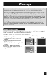
... television tuners/converters For example... Avoiding Ghost Images Displaying fixed images for extended periods of your cable company for their JVC TV remote control to select channels. We apologize for any inconvenience this may cause but are blank channels between , you specifi... company. To avoid this is detected and appears as available for scanning. Examples include, but it is receiving through the RF input), every channel number available from your viewing pattern. Warnings We have an important note for customers who subscribe to basic cable services...
... television tuners/converters For example... Avoiding Ghost Images Displaying fixed images for extended periods of your cable company for their JVC TV remote control to select channels. We apologize for any inconvenience this may cause but are blank channels between , you specifi... company. To avoid this is detected and appears as available for scanning. Examples include, but it is receiving through the RF input), every channel number available from your viewing pattern. Warnings We have an important note for customers who subscribe to basic cable services...
Instructions
Page 9
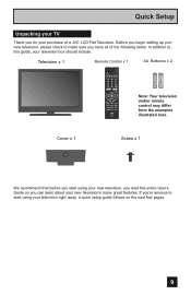
BACK F Remote Control x 1 POWER MODE TV STB VCR DVD AUDIO INPUT V1 V2 V3 V4 V5 1 2 3 4 5 6 7 8 9 RETURN + TUNE 0 TV - SUB T. Cover x 1 Screw x 1 We recommend that before you start using your new television, you read this guide, your television box should include: Television x 1 ...setting up your new television, please check to make sure you 're anxious to this entire User's Guide so you for your purchase of a JVC LCD Flat Television. If you have all of the following items. In addition to start using your television right away, a quick setup guide follows on...
BACK F Remote Control x 1 POWER MODE TV STB VCR DVD AUDIO INPUT V1 V2 V3 V4 V5 1 2 3 4 5 6 7 8 9 RETURN + TUNE 0 TV - SUB T. Cover x 1 Screw x 1 We recommend that before you start using your new television, you read this guide, your television box should include: Television x 1 ...setting up your new television, please check to make sure you 're anxious to this entire User's Guide so you for your purchase of a JVC LCD Flat Television. If you have all of the following items. In addition to start using your television right away, a quick setup guide follows on...
Instructions
Page 10
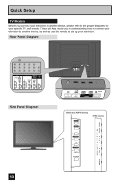
... L L L PR R R R 75 Ω (VHF/UHF) PHOTO VIEWER INPUT 1 SERVICE INPUT 2 DIGITAL AUDIO OPTICAL OUT 75 Ω (VHF/UHF) PHOTO VIEWER INPUT 1 SERVICE INPUT 2 DIGITAL AUDIO OPTICAL OUT X688 and XM48 series INPUT X788 series MENU INPUT MENU C H CHANNEL OK VOLUME BACK POWER VOL OK BACK POWER Quick Setup TV Models Before you in understanding how to connect...
... L L L PR R R R 75 Ω (VHF/UHF) PHOTO VIEWER INPUT 1 SERVICE INPUT 2 DIGITAL AUDIO OPTICAL OUT 75 Ω (VHF/UHF) PHOTO VIEWER INPUT 1 SERVICE INPUT 2 DIGITAL AUDIO OPTICAL OUT X688 and XM48 series INPUT X788 series MENU INPUT MENU C H CHANNEL OK VOLUME BACK POWER VOL OK BACK POWER Quick Setup TV Models Before you in understanding how to connect...

Instructions
Page 11
Remote Control MENU Quick Setup POWER MODE TV STB VCR DVD AUDIO INPUT V1 V2 V3 V4 V5 1 2 3 4 5 6 7 8 9 RETURN + TUNE 0 TV - CH + - DISPLAY SLEEP ML/MTS RM-C1450 TV RM-C1450 Notes: • For information on remote control buttons, see pages 58 - 66. • SUB CHANNEL and GUIDE buttons are for how to an ... many external device brands. See page 67 - 72 for digital channels. SUB T. VOL + MUTING BACK F OK AVORITE DVR STATUS SOUND VIDEO ASPECT GUIDE SUB CH TV/VCR C.C. If your TV is connected to program the remote control. 11
Remote Control MENU Quick Setup POWER MODE TV STB VCR DVD AUDIO INPUT V1 V2 V3 V4 V5 1 2 3 4 5 6 7 8 9 RETURN + TUNE 0 TV - CH + - DISPLAY SLEEP ML/MTS RM-C1450 TV RM-C1450 Notes: • For information on remote control buttons, see pages 58 - 66. • SUB CHANNEL and GUIDE buttons are for how to an ... many external device brands. See page 67 - 72 for digital channels. SUB T. VOL + MUTING BACK F OK AVORITE DVR STATUS SOUND VIDEO ASPECT GUIDE SUB CH TV/VCR C.C. If your TV is connected to program the remote control. 11
Instructions
Page 13
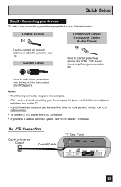
... examples. • After you are finished connecting your devices, plug the power cord into the nearest power outlet and turn on the TV. • If you follow these connections, you have a satellite television system, refer to make these diagrams and the television does not...player, see VCR Connection. • If you will use plugs like VCRs, DVD players, stereo amplifiers, game consoles, etc. Connecting your TV. No VCR Connection Cable or Antenna Output Coaxial Cable TV Rear Panel 75 Ω (VHF/UHF) PHOTO VIEWER INPUT 1 SERVICE INPUT 2 DIGITAL AUDIO OPTICAL OUT 13
... examples. • After you are finished connecting your devices, plug the power cord into the nearest power outlet and turn on the TV. • If you follow these connections, you have a satellite television system, refer to make these diagrams and the television does not...player, see VCR Connection. • If you will use plugs like VCRs, DVD players, stereo amplifiers, game consoles, etc. Connecting your TV. No VCR Connection Cable or Antenna Output Coaxial Cable TV Rear Panel 75 Ω (VHF/UHF) PHOTO VIEWER INPUT 1 SERVICE INPUT 2 DIGITAL AUDIO OPTICAL OUT 13
Instructions
Page 14
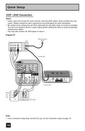
... for more information. • Be careful not to Input 1. Diagram #1 R LV IN OUT VCR IN OUT Cable or Antenna Output OR Coaxial Cable AUDIO AUDIO AUDIO COMPONENT AUDIO COMPONENT INPUT 3 S-VIDEO Y VIDEO PB L PR R INPUT 4 INPUT 5 / INPUT 1 AUDIO AUDIO OUT Y VIDEO VIDEO PB L L... L PR R R R 75 Ω (VHF/UHF) PHOTO VIEWER INPUT 1 SERVICE INPUT 2 DIGITAL AUDIO OPTICAL OUT TV Rear Panel Green Blue Red Y PB...
... for more information. • Be careful not to Input 1. Diagram #1 R LV IN OUT VCR IN OUT Cable or Antenna Output OR Coaxial Cable AUDIO AUDIO AUDIO COMPONENT AUDIO COMPONENT INPUT 3 S-VIDEO Y VIDEO PB L PR R INPUT 4 INPUT 5 / INPUT 1 AUDIO AUDIO OUT Y VIDEO VIDEO PB L L... L PR R R R 75 Ω (VHF/UHF) PHOTO VIEWER INPUT 1 SERVICE INPUT 2 DIGITAL AUDIO OPTICAL OUT TV Rear Panel Green Blue Red Y PB...
Instructions
Page 15
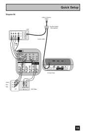
Diagram #2 R LV IN OUT VCR IN OUT OR Quick Setup Cable or Antenna Output IN Two-Way Splitter OUT OUT (Not supplied) Coaxial Cable AUDIO AUDIO AUDIO COMPONENT AUDIO COMPONENT INPUT 3 S-VIDEO Y VIDEO PB L PR R INPUT 4 INPUT 5 / INPUT 1 AUDIO AUDIO OUT Y VIDEO VIDEO PB L L L PR R R R Green Blue Red Y PB PR OUT AUDIO OUT R L DVD Player 75 Ω (VHF/UHF) PHOTO VIEWER INPUT 1 SERVICE INPUT 2 DIGITAL AUDIO OPTICAL OUT TV Rear Panel 15
Diagram #2 R LV IN OUT VCR IN OUT OR Quick Setup Cable or Antenna Output IN Two-Way Splitter OUT OUT (Not supplied) Coaxial Cable AUDIO AUDIO AUDIO COMPONENT AUDIO COMPONENT INPUT 3 S-VIDEO Y VIDEO PB L PR R INPUT 4 INPUT 5 / INPUT 1 AUDIO AUDIO OUT Y VIDEO VIDEO PB L L L PR R R R Green Blue Red Y PB PR OUT AUDIO OUT R L DVD Player 75 Ω (VHF/UHF) PHOTO VIEWER INPUT 1 SERVICE INPUT 2 DIGITAL AUDIO OPTICAL OUT TV Rear Panel 15
Instructions
Page 16
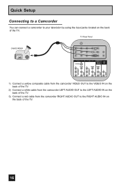
Quick Setup Connecting to a Camcorder You can connect a camcorder to the RIGHT AUDIO IN on the back of the TV. 16 TV Rear Panel CAMCORDER INPUT 3 S-VIDEO Y VIDEO PB L PR R INPUT 4 INPUT 5 / INPUT 1 AUDIO AUDIO OUT Y VIDEO VIDEO PB L L L PR R R R AUDIO AUDIO AUDIO COMPONENT AUDIO COMPONENT 1) Connect a yellow composite cable ...on the back of the TV. 2) Connect a white cable from the camcorder LEFT AUDIO OUT to the LEFT AUDIO IN on the back of the TV. 3) Connect a red cable from the camcorder RIGHT AUDIO OUT to your television by using the input jacks located on the ...
Quick Setup Connecting to a Camcorder You can connect a camcorder to the RIGHT AUDIO IN on the back of the TV. 16 TV Rear Panel CAMCORDER INPUT 3 S-VIDEO Y VIDEO PB L PR R INPUT 4 INPUT 5 / INPUT 1 AUDIO AUDIO OUT Y VIDEO VIDEO PB L L L PR R R R AUDIO AUDIO AUDIO COMPONENT AUDIO COMPONENT 1) Connect a yellow composite cable ...on the back of the TV. 2) Connect a white cable from the camcorder LEFT AUDIO OUT to the LEFT AUDIO IN on the back of the TV. 3) Connect a red cable from the camcorder RIGHT AUDIO OUT to your television by using the input jacks located on the ...
Instructions
Page 17
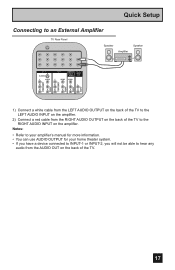
... theater system. • If you have a device connected to INPUT-1 or INPUT-2, you will not be able to the RIGHT AUDIO INPUT on the back of the TV. 17 Quick Setup Connecting to an External Amplifier TV Rear Panel Speaker Amplifier Speaker INPUT 3 S-VIDEO Y VIDEO PB L PR R INPUT 4 INPUT 5 / INPUT 1 AUDIO AUDIO OUT Y VIDEO VIDEO PB L L L PR R R R AUDIO AUDIO...
... theater system. • If you have a device connected to INPUT-1 or INPUT-2, you will not be able to the RIGHT AUDIO INPUT on the back of the TV. 17 Quick Setup Connecting to an External Amplifier TV Rear Panel Speaker Amplifier Speaker INPUT 3 S-VIDEO Y VIDEO PB L PR R INPUT 4 INPUT 5 / INPUT 1 AUDIO AUDIO OUT Y VIDEO VIDEO PB L L L PR R R R AUDIO AUDIO...
Instructions
Page 18
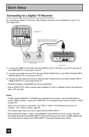
... order to digitally connect the television with a DTV decoder. HDMI to DVI Cable LR AUDIO OUT DIGITAL OUT 75 Ω (VHF/UHF) PHOTO VIEWER INPUT 1 SERVICE INPUT 2 DIGITAL AUDIO OPTICAL OUT DTV Decoder TV Rear Panel 1) Connect the HDMI to DVI Cable from the DTV decoder LEFT AUDIO OUT to the LEFT AUDIO...
... order to digitally connect the television with a DTV decoder. HDMI to DVI Cable LR AUDIO OUT DIGITAL OUT 75 Ω (VHF/UHF) PHOTO VIEWER INPUT 1 SERVICE INPUT 2 DIGITAL AUDIO OPTICAL OUT DTV Decoder TV Rear Panel 1) Connect the HDMI to DVI Cable from the DTV decoder LEFT AUDIO OUT to the LEFT AUDIO...
Instructions
Page 19
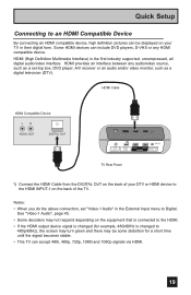
... HDMI Compatible Device LR AUDIO OUT DIGITAL OUT 75 Ω (VHF/UHF) PHOTO VIEWER INPUT 1 SERVICE INPUT 2 DIGITAL AUDIO OPTICAL OUT TV Rear Panel 1) Connect the HDMI Cable from the DIGITAL OUT on the back of the TV. Notes: • When you do the above connection, set -top box, DVD player... turn green and there may be displayed on the back of your TV in the External Input menu to Digital. HDMI (High Definition Multimedia Interface) is changed (for a short time until the signal becomes stable. • This TV can accept 480i, 480p, 720p, 1080i and 1080p signals via HDMI...
... HDMI Compatible Device LR AUDIO OUT DIGITAL OUT 75 Ω (VHF/UHF) PHOTO VIEWER INPUT 1 SERVICE INPUT 2 DIGITAL AUDIO OPTICAL OUT TV Rear Panel 1) Connect the HDMI Cable from the DIGITAL OUT on the back of the TV. Notes: • When you do the above connection, set -top box, DVD player... turn green and there may be displayed on the back of your TV in the External Input menu to Digital. HDMI (High Definition Multimedia Interface) is changed (for a short time until the signal becomes stable. • This TV can accept 480i, 480p, 720p, 1080i and 1080p signals via HDMI...
Instructions
Page 20
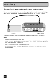
...optical output You can only output digital audio. • In order to your HDMI device. 20 The signal that has an optical digital input terminal by using your amplifier. • You cannot output sound from your Optical Output connection if the audio source is output can be PCM... or DOLBY DIGITAL. 75 Ω (VHF/UHF) PHOTO VIEWER INPUT 1 SERVICE INPUT 2 DIGITAL AUDIO OPTICAL OUT Amplifier TV Rear Panel 1) Connect the optical cable from your owners manual on Optical Out in the Initial Setup Menu. Quick Setup Connecting...
...optical output You can only output digital audio. • In order to your HDMI device. 20 The signal that has an optical digital input terminal by using your amplifier. • You cannot output sound from your Optical Output connection if the audio source is output can be PCM... or DOLBY DIGITAL. 75 Ω (VHF/UHF) PHOTO VIEWER INPUT 1 SERVICE INPUT 2 DIGITAL AUDIO OPTICAL OUT Amplifier TV Rear Panel 1) Connect the optical cable from your owners manual on Optical Out in the Initial Setup Menu. Quick Setup Connecting...
Instructions
Page 21
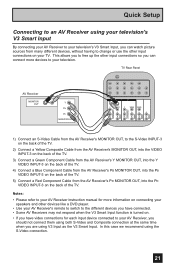
...on. • If you have video connections for each input device connected to the S-Video INPUT-3 on the back of the TV. 2) Connect a Yellow Composite Cable from the AV Receiver's MONITOR OUT, into the VIDEO INPUT-3 on the back of the TV. 3) Connect a Green Component Cable from the AV ... so you can watch picture sources from the AV Receiver's PR MONITOR OUT, into the PB VIDEO INPUT-3 on your TV. TV Rear Panel AV Receiver MONITOR OUT Y PB PR MONITOR OUT INPUT 3 S-VIDEO Y VIDEO INPUT 4 Y VIDEO VIDEO PB L PB L L L PR R PR R R R AUDIO AUDIO AUDIO COMPONENT AUDIO COMPONENT ...
...on. • If you have video connections for each input device connected to the S-Video INPUT-3 on the back of the TV. 2) Connect a Yellow Composite Cable from the AV Receiver's MONITOR OUT, into the VIDEO INPUT-3 on the back of the TV. 3) Connect a Green Component Cable from the AV ... so you can watch picture sources from the AV Receiver's PR MONITOR OUT, into the PB VIDEO INPUT-3 on your TV. TV Rear Panel AV Receiver MONITOR OUT Y PB PR MONITOR OUT INPUT 3 S-VIDEO Y VIDEO INPUT 4 Y VIDEO VIDEO PB L PB L L L PR R PR R R R AUDIO AUDIO AUDIO COMPONENT AUDIO COMPONENT ...
Instructions
Page 25
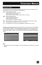
... in a main menu screen • Move through a submenu screen • Move to the highlighted or selected item in a menu. Menu Initial Setup - + Tuner Setup External Input Picture Adjust Sound Adjust Clock/Timers Interactive Plug-in Photo Viewer Auto Demo Menu Front Menu Video Status Aspect Auto Tuner Setup Menu Exit Menu... selected. The ones you should press the button named on your new television. To bring up the onscreen menu, press the MENU button on the TV's side panel instead of the television's onscreen displays. 25
... in a main menu screen • Move through a submenu screen • Move to the highlighted or selected item in a menu. Menu Initial Setup - + Tuner Setup External Input Picture Adjust Sound Adjust Clock/Timers Interactive Plug-in Photo Viewer Auto Demo Menu Front Menu Video Status Aspect Auto Tuner Setup Menu Exit Menu... selected. The ones you should press the button named on your new television. To bring up the onscreen menu, press the MENU button on the TV's side panel instead of the television's onscreen displays. 25
Instructions
Page 26
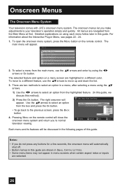
... CAPITAL LETTERS. • Some menu items may not appear in menu screens when certain aspect ratios or inputs are two methods to normal television viewing. Pressing MENU on using each menu follow later in the following ... Auto Tuner Setup appear. The selected feature and option on the remote control. Menu Initial Setup - + Tuner Setup External Input Picture Adjust Sound Adjust Clock/Timers Interactive Plug-in Menu, see pages 22 - 24. 1. The onscreen menus let you to.... 26 Onscreen Menus The Onscreen Menu System Your television comes with JVC's onscreen menu system.
... CAPITAL LETTERS. • Some menu items may not appear in menu screens when certain aspect ratios or inputs are two methods to normal television viewing. Pressing MENU on using each menu follow later in the following ... Auto Tuner Setup appear. The selected feature and option on the remote control. Menu Initial Setup - + Tuner Setup External Input Picture Adjust Sound Adjust Clock/Timers Interactive Plug-in Menu, see pages 22 - 24. 1. The onscreen menus let you to.... 26 Onscreen Menus The Onscreen Menu System Your television comes with JVC's onscreen menu system.
Instructions
Page 27
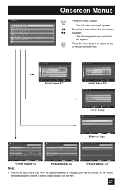
... Digital Antenna Level Tuner Diagnostic (Service Use Only) Select OK BACK MENU Operate Back Exit Tuner Setup External Input HDMI Size Video-1 Audio Video Input Label Auto Auto Select Operate Back Back Menu Exit External Input Picture Adjust Tint [ 00 ] R Color [+06 ] Picture[+10 ] Bright [ 00 ] Detail [+06 ] Energy Saver Mode Dynamic 1/3 ... 2/3 Select Operate Back Back Menu Exit Picture Adjust 3/3 Note: • The HDMI Size menu can only be displayed when a 480p picture signal is input to the HDMI terminal and the picture is being displayed on the screen. 27
... Digital Antenna Level Tuner Diagnostic (Service Use Only) Select OK BACK MENU Operate Back Exit Tuner Setup External Input HDMI Size Video-1 Audio Video Input Label Auto Auto Select Operate Back Back Menu Exit External Input Picture Adjust Tint [ 00 ] R Color [+06 ] Picture[+10 ] Bright [ 00 ] Detail [+06 ] Energy Saver Mode Dynamic 1/3 ... 2/3 Select Operate Back Back Menu Exit Picture Adjust 3/3 Note: • The HDMI Size menu can only be displayed when a 480p picture signal is input to the HDMI terminal and the picture is being displayed on the screen. 27

Instructions
Page 28
Onscreen Menus Menu Initial Setup - + Tuner Setup External Input Picture Adjust Sound Adjust Clock/Timers Interactive Plug-in Photo Viewer Auto Demo Menu π† √® Press the MENU button The left main ...
Onscreen Menus Menu Initial Setup - + Tuner Setup External Input Picture Adjust Sound Adjust Clock/Timers Interactive Plug-in Photo Viewer Auto Demo Menu π† √® Press the MENU button The left main ...
Instructions
Page 30
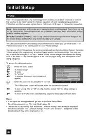
...you to block channels or content that you set the password, see following pages for setting each item) Notes: • If you input the wrong password, go back to be inappropriate for information on specifications designed for programming broadcast from Canada), and movie ratings. Even ...the MENU button To "Initial Setup" To enter To "V-Chip" To operate (Password input screen will appear) Enter the password by using the 10 keypad Initial Setup > V-Chip V-Chip On Set US TV Ratings Set Movie Ratings Set Canadian Ratings English Set Canadian Ratings French Advanced V-Chip Rating...
...you to block channels or content that you set the password, see following pages for setting each item) Notes: • If you input the wrong password, go back to be inappropriate for information on specifications designed for programming broadcast from Canada), and movie ratings. Even ...the MENU button To "Initial Setup" To enter To "V-Chip" To operate (Password input screen will appear) Enter the password by using the 10 keypad Initial Setup > V-Chip V-Chip On Set US TV Ratings Set Movie Ratings Set Canadian Ratings English Set Canadian Ratings French Advanced V-Chip Rating...
Instructions
Page 32
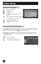
... of all TV 14 shows, move the cursor to the correct location. Initial Setup Setting US V-Chip Ratings π† √® π† √® √® π† √® Press the MENU button To "Initial Setup" To enter To "V-Chip" To operate (Password input screen will... appear) Enter the password by using the 10 keypad The V-Chip main screen will appear To turn the locking feature on the top row, everything in the column (TV PG, TV G, etc.) with the content row (V/FV, S, etc.) ...
... of all TV 14 shows, move the cursor to the correct location. Initial Setup Setting US V-Chip Ratings π† √® π† √® √® π† √® Press the MENU button To "Initial Setup" To enter To "V-Chip" To operate (Password input screen will... appear) Enter the password by using the 10 keypad The V-Chip main screen will appear To turn the locking feature on the top row, everything in the column (TV PG, TV G, etc.) with the content row (V/FV, S, etc.) ...
Instructions
Page 33
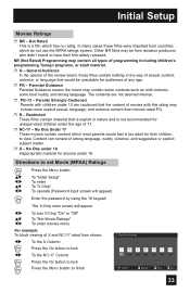
... Movie (MPAA) Ratings Press the MENU button π† √® π† √® To "Initial Setup" To enter To "V-Chip" To operate (Password input screen will appear) Enter the password by using the 10 keypad √® π† √® The V-Chip main screen will appear To turn...
... Movie (MPAA) Ratings Press the MENU button π† √® π† √® To "Initial Setup" To enter To "V-Chip" To operate (Password input screen will appear) Enter the password by using the 10 keypad √® π† √® The V-Chip main screen will appear To turn...


