Instructions
Page 2
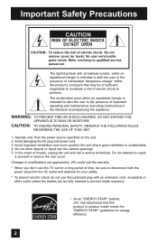
... an "ENERGY STAR®" partner, JVC has determined that this TV set for energy efficiency. 2 Do not remove cover (or back). Refer servicing to repair it yourself or remove the rear cover. In the event of electric shock to constitute a risk of trouble, unplug the unit and call a service technician. The lightning flash with an extension cord, receptacle or other outlet unless...
... an "ENERGY STAR®" partner, JVC has determined that this TV set for energy efficiency. 2 Do not remove cover (or back). Refer servicing to repair it yourself or remove the rear cover. In the event of electric shock to constitute a risk of trouble, unplug the unit and call a service technician. The lightning flash with an extension cord, receptacle or other outlet unless...
Instructions
Page 5
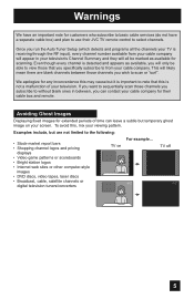
... 5 Even though every channel is receiving through the RF input), every channel number available from your cable company for extended periods of your screen. Warnings We have an important note for customers who subscribe to basic cable services (do not have a separate cable box) and plan to use their cable box and remote. Avoiding Ghost Images Displaying fixed images for their JVC TV remote control to select channels. This will...
... 5 Even though every channel is receiving through the RF input), every channel number available from your cable company for extended periods of your screen. Warnings We have an important note for customers who subscribe to basic cable services (do not have a separate cable box) and plan to use their cable box and remote. Avoiding Ghost Images Displaying fixed images for their JVC TV remote control to select channels. This will...
Instructions
Page 10
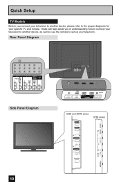
... INPUT 1 SERVICE INPUT 2 DIGITAL AUDIO OPTICAL OUT 75 Ω (VHF/UHF) PHOTO VIEWER INPUT 1 SERVICE INPUT 2 DIGITAL AUDIO OPTICAL OUT X688 and XM48 series INPUT X788 series MENU INPUT MENU C H CHANNEL OK VOLUME BACK POWER VOL OK BACK POWER These will help assist you connect your television to another device, as well as use the remote to the proper diagrams for your television. Quick Setup TV Models Before you in understanding how to connect your television to another device, please refer to set up your specific TV and remote...
... INPUT 1 SERVICE INPUT 2 DIGITAL AUDIO OPTICAL OUT 75 Ω (VHF/UHF) PHOTO VIEWER INPUT 1 SERVICE INPUT 2 DIGITAL AUDIO OPTICAL OUT X688 and XM48 series INPUT X788 series MENU INPUT MENU C H CHANNEL OK VOLUME BACK POWER VOL OK BACK POWER These will help assist you connect your television to another device, as well as use the remote to the proper diagrams for your television. Quick Setup TV Models Before you in understanding how to connect your television to another device, please refer to set up your specific TV and remote...
Instructions
Page 14
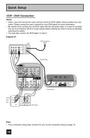
... 1. Diagram #1 R LV IN OUT VCR IN OUT Cable or Antenna Output OR Coaxial Cable AUDIO AUDIO AUDIO COMPONENT AUDIO COMPONENT INPUT 3 S-VIDEO Y VIDEO PB L PR R INPUT 4 INPUT 5 / INPUT 1 AUDIO AUDIO OUT Y VIDEO VIDEO PB L L L PR R R R 75 Ω (VHF/UHF) PHOTO VIEWER INPUT 1 SERVICE INPUT 2 DIGITAL AUDIO OPTICAL OUT TV Rear Panel Green Blue Red Y PB PR OUT AUDIO OUT R L DVD Player Note: • If this connection setup does not work for DVD cables. Quick Setup VCR • DVD Connection Notes: • Green, blue and red are the most common colors for...
... 1. Diagram #1 R LV IN OUT VCR IN OUT Cable or Antenna Output OR Coaxial Cable AUDIO AUDIO AUDIO COMPONENT AUDIO COMPONENT INPUT 3 S-VIDEO Y VIDEO PB L PR R INPUT 4 INPUT 5 / INPUT 1 AUDIO AUDIO OUT Y VIDEO VIDEO PB L L L PR R R R 75 Ω (VHF/UHF) PHOTO VIEWER INPUT 1 SERVICE INPUT 2 DIGITAL AUDIO OPTICAL OUT TV Rear Panel Green Blue Red Y PB PR OUT AUDIO OUT R L DVD Player Note: • If this connection setup does not work for DVD cables. Quick Setup VCR • DVD Connection Notes: • Green, blue and red are the most common colors for...
Instructions
Page 18
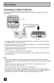
... shifted. Access the "HDMI Size" in the External Input menu to adjust it. (Refer to page 45.) • When you use a DVI to HDMI adapter this connection must be used with the HDMI INPUT-1. • When setting the "Video-1 Audio - HDMI to DVI Cable LR AUDIO OUT DIGITAL OUT 75 Ω (VHF/UHF) PHOTO VIEWER INPUT 1 SERVICE INPUT 2 DIGITAL AUDIO OPTICAL OUT DTV Decoder TV Rear Panel 1) Connect the HDMI to DVI Cable from the DTV decoder LEFT AUDIO OUT to the LEFT AUDIO INPUT HDMI AUDIO IN...
... shifted. Access the "HDMI Size" in the External Input menu to adjust it. (Refer to page 45.) • When you use a DVI to HDMI adapter this connection must be used with the HDMI INPUT-1. • When setting the "Video-1 Audio - HDMI to DVI Cable LR AUDIO OUT DIGITAL OUT 75 Ω (VHF/UHF) PHOTO VIEWER INPUT 1 SERVICE INPUT 2 DIGITAL AUDIO OPTICAL OUT DTV Decoder TV Rear Panel 1) Connect the HDMI to DVI Cable from the DTV decoder LEFT AUDIO OUT to the LEFT AUDIO INPUT HDMI AUDIO IN...
Instructions
Page 19
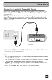
... industry supported, uncompressed, all digital audio/video interface. Notes: • When you do the above connection, set -top box, DVD player, A/V receiver or an audio and/or video monitor, such as a digital television (DTV). HDMI Cable HDMI Compatible Device LR AUDIO OUT DIGITAL OUT 75 Ω (VHF/UHF) PHOTO VIEWER INPUT 1 SERVICE INPUT 2 DIGITAL AUDIO OPTICAL OUT TV Rear Panel 1) Connect the HDMI Cable from the DIGITAL OUT on the back of the TV. Some HDMI devices can accept 480i, 480p, 720p, 1080i and 1080p signals via HDMI...
... industry supported, uncompressed, all digital audio/video interface. Notes: • When you do the above connection, set -top box, DVD player, A/V receiver or an audio and/or video monitor, such as a digital television (DTV). HDMI Cable HDMI Compatible Device LR AUDIO OUT DIGITAL OUT 75 Ω (VHF/UHF) PHOTO VIEWER INPUT 1 SERVICE INPUT 2 DIGITAL AUDIO OPTICAL OUT TV Rear Panel 1) Connect the HDMI Cable from the DIGITAL OUT on the back of the TV. Some HDMI devices can accept 480i, 480p, 720p, 1080i and 1080p signals via HDMI...
Instructions
Page 20
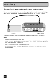
... order to use the optical output connection, select PCM or DOLBY DIGITAL on using your amplifier. • You cannot output sound from your Optical Output connection if the audio source is output can connect an amplifier that is from your HDMI device. 20 Quick Setup Connecting to an amplifier using your optical output You can be PCM or DOLBY DIGITAL. 75 Ω (VHF/UHF) PHOTO VIEWER INPUT 1 SERVICE INPUT 2 DIGITAL AUDIO OPTICAL OUT Amplifier TV Rear Panel 1) Connect the optical cable from underneath the television to...
... order to use the optical output connection, select PCM or DOLBY DIGITAL on using your amplifier. • You cannot output sound from your Optical Output connection if the audio source is output can connect an amplifier that is from your HDMI device. 20 Quick Setup Connecting to an amplifier using your optical output You can be PCM or DOLBY DIGITAL. 75 Ω (VHF/UHF) PHOTO VIEWER INPUT 1 SERVICE INPUT 2 DIGITAL AUDIO OPTICAL OUT Amplifier TV Rear Panel 1) Connect the optical cable from underneath the television to...
Instructions
Page 21
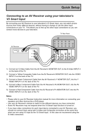
... Receiver instruction manual for more devices to change or use the other input connections on your TV. TV Rear Panel AV Receiver MONITOR OUT Y PB PR MONITOR OUT INPUT 3 S-VIDEO Y VIDEO INPUT 4 Y VIDEO VIDEO PB L PB L L L PR R PR R R R AUDIO AUDIO AUDIO COMPONENT AUDIO COMPONENT 1) Connect an S-Video Cable from the AV Receiver's MONITOR OUT, to your AV Receiver's remote to switch to the different devices you have connected. • Some AV Receivers may not respond when the V3 Smart Input function is turned on. • If you have video connections...
... Receiver instruction manual for more devices to change or use the other input connections on your TV. TV Rear Panel AV Receiver MONITOR OUT Y PB PR MONITOR OUT INPUT 3 S-VIDEO Y VIDEO INPUT 4 Y VIDEO VIDEO PB L PB L L L PR R PR R R R AUDIO AUDIO AUDIO COMPONENT AUDIO COMPONENT 1) Connect an S-Video Cable from the AV Receiver's MONITOR OUT, to your AV Receiver's remote to switch to the different devices you have connected. • Some AV Receivers may not respond when the V3 Smart Input function is turned on. • If you have video connections...
Instructions
Page 23
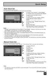
... used when it is "Auto (Digital)". If you selected "Auto (Digital)" To select a receiving digital channel To "Time Zone" To select your clock manually, choose "Manual". Set Clock Mode Channel Time Time Zone D.S.T. can be selected only when Mode is set to reset the clock after a power interruption. Note: • You will move to reset the clock after a power interruption. Quick Setup Auto Clock Set You may not be set correctly depending on the broadcasting signal and receiving conditions. Auto (Analog...
... used when it is "Auto (Digital)". If you selected "Auto (Digital)" To select a receiving digital channel To "Time Zone" To select your clock manually, choose "Manual". Set Clock Mode Channel Time Time Zone D.S.T. can be selected only when Mode is set to reset the clock after a power interruption. Note: • You will move to reset the clock after a power interruption. Quick Setup Auto Clock Set You may not be set correctly depending on the broadcasting signal and receiving conditions. Auto (Analog...
Instructions
Page 27
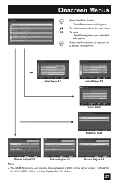
... BACK button to return to the previous menu screen Initial Setup 1/2 Noise Muting Language Front Panel Lock V-Chip Set Lock Code Closed Caption On English Off Select Operate BACK Back MENU Exit Initial Setup 1/2 Initial Setup Auto Shut Off Software Version Power Indicator Optical Out Quick Start-up 2/2 Off High PCM Off Select Operate BACK Back MENU Exit Initial Setup 2/2 - + Tuner Setup Auto Tuner Setup Channel Summary Find Channel Digital Antenna Level Tuner Diagnostic (Service Use Only) Select OK BACK MENU Operate Back Exit Tuner Setup External Input HDMI Size Video...
... BACK button to return to the previous menu screen Initial Setup 1/2 Noise Muting Language Front Panel Lock V-Chip Set Lock Code Closed Caption On English Off Select Operate BACK Back MENU Exit Initial Setup 1/2 Initial Setup Auto Shut Off Software Version Power Indicator Optical Out Quick Start-up 2/2 Off High PCM Off Select Operate BACK Back MENU Exit Initial Setup 2/2 - + Tuner Setup Auto Tuner Setup Channel Summary Find Channel Digital Antenna Level Tuner Diagnostic (Service Use Only) Select OK BACK MENU Operate Back Exit Tuner Setup External Input HDMI Size Video...

Instructions
Page 38
... Text Color, Edge Color, Background Color: Auto, White, Black, Red, Green, Blue, Yellow, Magenta, or Cyan Press the MENU button when finished Closed Caption > Appearance 1/2 Preview Closed Caption Sample Appearance Mode Font Size Font Style Text / Edge Opacity Background Opacity Select Operate Manual Standard Auto Solid Solid BACK Back MENU Exit Closed Caption > Appearance 2/2 Preview Closed Caption Sample Text Color Edge Color Background Color White White Black Select OK BACK MENU Operate Back Exit All fonts are usually found on closed captioning will display...
... Text Color, Edge Color, Background Color: Auto, White, Black, Red, Green, Blue, Yellow, Magenta, or Cyan Press the MENU button when finished Closed Caption > Appearance 1/2 Preview Closed Caption Sample Appearance Mode Font Size Font Style Text / Edge Opacity Background Opacity Select Operate Manual Standard Auto Solid Solid BACK Back MENU Exit Closed Caption > Appearance 2/2 Preview Closed Caption Sample Text Color Edge Color Background Color White White Black Select OK BACK MENU Operate Back Exit All fonts are usually found on closed captioning will display...
Instructions
Page 41
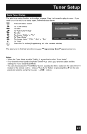
Tuner Setup Auto Tuner Setup The auto tuner setup function is finished when the message "Programming Over !" If you need to select "Scan Mode" • If no channels were found using Auto Tuner Setup, check your antenna cable and the settings for Tuner Mode/Scan Mode. • You can also access the "Front Menu" screen by using the MENU button on page 24 as the interactive plug-in menu. Notes: • When the Tuner Mode is set to "Cable", it is possible to run the auto tuner setup again, follow...
Tuner Setup Auto Tuner Setup The auto tuner setup function is finished when the message "Programming Over !" If you need to select "Scan Mode" • If no channels were found using Auto Tuner Setup, check your antenna cable and the settings for Tuner Mode/Scan Mode. • You can also access the "Front Menu" screen by using the MENU button on page 24 as the interactive plug-in menu. Notes: • When the Tuner Mode is set to "Cable", it is possible to run the auto tuner setup again, follow...
Instructions
Page 46
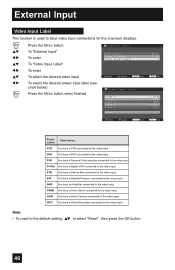
... default setting, π† to label video input connections for the onscreen displays. π† √® π† √® π† √® Press the MENU button To "External Input" To enter To "Video Input Label" To enter To select the desired video input To select the desired preset input label (see chart below) Press the MENU button when finished External Input HDMI Size Video-1 Audio Video Input Label Select Operate Back Back Video Input Label Video-1 Video-2 Video-3 Video-4 Video-5 Reset...
... default setting, π† to label video input connections for the onscreen displays. π† √® π† √® π† √® Press the MENU button To "External Input" To enter To "Video Input Label" To enter To select the desired video input To select the desired preset input label (see chart below) Press the MENU button when finished External Input HDMI Size Video-1 Audio Video Input Label Select Operate Back Back Video Input Label Video-1 Video-2 Video-3 Video-4 Video-5 Reset...
Instructions
Page 55
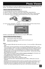
... and then display the Photo Viewer Screen. In this case, the message, "There is no photo to connect. • Compatible file format is "Exif version 2.1, based on DCF version 1.0". • Supported file formats are connecting to turn the power off on the device containing your photos. 2) Switch to "PHOTO" mode if your device has a mode switch (VIDEO/PHOTO). 3) Turn on this TV by using a USB cable. You are able to view them...
... and then display the Photo Viewer Screen. In this case, the message, "There is no photo to connect. • Compatible file format is "Exif version 2.1, based on DCF version 1.0". • Supported file formats are connecting to turn the power off on the device containing your photos. 2) Switch to "PHOTO" mode if your device has a mode switch (VIDEO/PHOTO). 3) Turn on this TV by using a USB cable. You are able to view them...
Instructions
Page 60
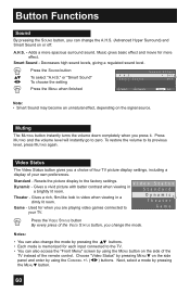
... four TV picture display settings, including a display of your TV. Used for when you are playing video games connected to video when viewing in a brightly lit room. Smart Sound - Standard - Gives a rich, film-like look to Game your own preferences. A.H.S. - Decreases high sound levels, giving a regulated sound level. π† √® Press the SOUND button To select "A.H.S." or "Smart Sound" To choose the setting Press the MENU when finished A.H.S. Resets the picture display to...
... four TV picture display settings, including a display of your TV. Used for when you are playing video games connected to video when viewing in a brightly lit room. Smart Sound - Standard - Gives a rich, film-like look to Game your own preferences. A.H.S. - Decreases high sound levels, giving a regulated sound level. π† √® Press the SOUND button To select "A.H.S." or "Smart Sound" To choose the setting Press the MENU when finished A.H.S. Resets the picture display to...
Instructions
Page 67
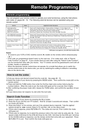
DVD Player, DVD Recorder Home Theater in Box, AUDIO Power on/off, Audio Input Selection (V1 button), Volume up /down , Muting, 72 Receiver DVD operation buttons: Menu on/off , Arrow buttons, OK/Enter, Back, Guide (EPG), 69, 70 TV/VCR, Closed Caption, Eject ( ), Rewind ( ), Playback ( ), Forward ( ), Record ( ), Stop ( ), Pause ( ). How to set . Then confirm the mode LED goes out. 5) If there was a response, press RETURN+/TV. Device Mode Applied for the AUDIO) without a response, use the remote that allows...
DVD Player, DVD Recorder Home Theater in Box, AUDIO Power on/off, Audio Input Selection (V1 button), Volume up /down , Muting, 72 Receiver DVD operation buttons: Menu on/off , Arrow buttons, OK/Enter, Back, Guide (EPG), 69, 70 TV/VCR, Closed Caption, Eject ( ), Rewind ( ), Playback ( ), Forward ( ), Record ( ), Stop ( ), Pause ( ). How to set . Then confirm the mode LED goes out. 5) If there was a response, press RETURN+/TV. Device Mode Applied for the AUDIO) without a response, use the remote that allows...
Instructions
Page 74
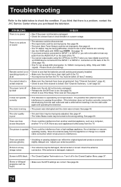
... Color may be interference from an HDMI device connected to see if the Sleep Timer was not reset. There are correct. Picture is on the back of the TV. • You cannot output audio using the OPTICAL OUTPUT when you have a device connected to INPUT-1 or INPUT-2, you have digital sound from another electrical appliance, such as a computer, another TV or VCR. Check the antenna connection. Screen is 80% black • The Closed Caption Text mode...
... Color may be interference from an HDMI device connected to see if the Sleep Timer was not reset. There are correct. Picture is on the back of the TV. • You cannot output audio using the OPTICAL OUTPUT when you have a device connected to INPUT-1 or INPUT-2, you have digital sound from another electrical appliance, such as a computer, another TV or VCR. Check the antenna connection. Screen is 80% black • The Closed Caption Text mode...
Instructions
Page 75
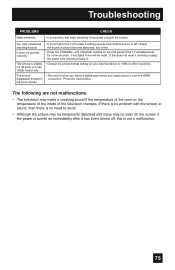
... or other resolution. The Digital Tuner will be temporarily disturbed and noise may make crackling sounds when first turned on the side panel of the television changes. the menu screen The following are not malfunctions. • The television may be seen on the screen if the power is turned on your input source is normal for the TV to worry. • Although the picture may be reset. Troubleshooting PROBLEMS CHECK Static...
... or other resolution. The Digital Tuner will be temporarily disturbed and noise may make crackling sounds when first turned on the side panel of the television changes. the menu screen The following are not malfunctions. • The television may be seen on the screen if the power is turned on your input source is normal for the TV to worry. • Although the picture may be reset. Troubleshooting PROBLEMS CHECK Static...
Instructions
Page 76
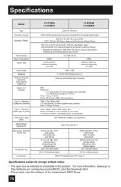
...; Personal computer compatibility cannot be guaranteed. Specifications Model Type Reception Format Reception Range Power Source Power Consumption Screen Size Audio Output Speakers Antenna Terminal (VHF/UHF, ATSC/DIGITAL CABLE IN) Input 3, 4, 5 Terminal Input 3, 4 Terminal (Component Terminal) Input 1, 2 Terminal (HDMI Input Terminal) Audio Output Jacks (FIX) Optical Output Digital Audio Dimensions (inch/cm) W X H X D Weight (lbs / kg) Accessories LT-37X688 LT-37XM48 LT-42X688 LT-42XM48 LCD Flat Television NTSC, BTSC System (Multi-Channel Sound) ATSC Terrestrial, Digital Cable VHF 2 to...
...; Personal computer compatibility cannot be guaranteed. Specifications Model Type Reception Format Reception Range Power Source Power Consumption Screen Size Audio Output Speakers Antenna Terminal (VHF/UHF, ATSC/DIGITAL CABLE IN) Input 3, 4, 5 Terminal Input 3, 4 Terminal (Component Terminal) Input 1, 2 Terminal (HDMI Input Terminal) Audio Output Jacks (FIX) Optical Output Digital Audio Dimensions (inch/cm) W X H X D Weight (lbs / kg) Accessories LT-37X688 LT-37XM48 LT-42X688 LT-42XM48 LCD Flat Television NTSC, BTSC System (Multi-Channel Sound) ATSC Terrestrial, Digital Cable VHF 2 to...
Instructions
Page 77
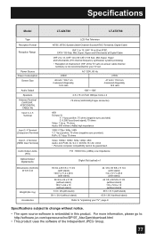
... Model LT-42X788 LT-47X788 Type Reception Format Reception Range Power Source Power Consumption Screen Size Audio Output Speakers Antenna Terminal (VHF/UHF, ATSC/DIGITAL CABLE IN) Input 3, 4, 5 Terminal Input 3, 4 Terminal (Component Terminal) Input 1, 2 Terminal (HDMI Input Terminal) Audio Output Jacks (FIX) Optical Output Digital Audio Dimensions (inch/cm) W X H X D Weight (lbs / kg) Accessories LCD Flat Television NTSC, BTSC System (Multi-Channel Sound) ATSC Terrestrial, Digital Cable VHF 2 to 13, UHF 14 to 69 at ATSC, CATV 135 Sub, Mid, Super, Hyper and Ultra bands at Digital Cable...
... Model LT-42X788 LT-47X788 Type Reception Format Reception Range Power Source Power Consumption Screen Size Audio Output Speakers Antenna Terminal (VHF/UHF, ATSC/DIGITAL CABLE IN) Input 3, 4, 5 Terminal Input 3, 4 Terminal (Component Terminal) Input 1, 2 Terminal (HDMI Input Terminal) Audio Output Jacks (FIX) Optical Output Digital Audio Dimensions (inch/cm) W X H X D Weight (lbs / kg) Accessories LCD Flat Television NTSC, BTSC System (Multi-Channel Sound) ATSC Terrestrial, Digital Cable VHF 2 to 13, UHF 14 to 69 at ATSC, CATV 135 Sub, Mid, Super, Hyper and Ultra bands at Digital Cable...


