Instructions
Page 2
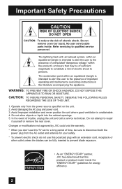
... to alert the user to the presence of uninsulated "dangerous voltage" within an equilateral triangle is unattainable. 4. Changes or modifications not approved by JVC could void the warranty. * When you don't use this product or product model meets the "ENERGY STAR®" guidelines for a long period...call a service technician. Operate only from the AC outlet and antenna for your safety. * To prevent electric shock do not use this TV set for energy efficiency. 2 Refer servicing to repair it yourself or remove the rear cover. The exclamation point within the product's enclosure that...
... to alert the user to the presence of uninsulated "dangerous voltage" within an equilateral triangle is unattainable. 4. Changes or modifications not approved by JVC could void the warranty. * When you don't use this product or product model meets the "ENERGY STAR®" guidelines for a long period...call a service technician. Operate only from the AC outlet and antenna for your safety. * To prevent electric shock do not use this TV set for energy efficiency. 2 Refer servicing to repair it yourself or remove the rear cover. The exclamation point within the product's enclosure that...
Instructions
Page 4
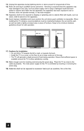
... of time. 14) Refer all servicing to dripping or splashing and no objects filled with liquids, such as possible. The main power supply for this TV is controlled by inserting or removing the power plug. 19) Batteries shall not be placed on the floor so as to keep cords out of... the way. - Place the TV as sunshine, fire or the like. 4 Keep to the outlet as vases, shall be exposed to allow satisfactory cooling. 18) Make enough room for installation...
... of time. 14) Refer all servicing to dripping or splashing and no objects filled with liquids, such as possible. The main power supply for this TV is controlled by inserting or removing the power plug. 19) Batteries shall not be placed on the floor so as to keep cords out of... the way. - Place the TV as sunshine, fire or the like. 4 Keep to the outlet as vases, shall be exposed to allow satisfactory cooling. 18) Make enough room for installation...
Instructions
Page 5
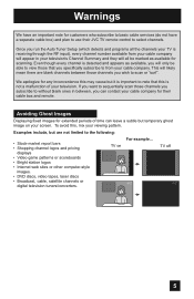
... and they will only be marked as available, you will all the channels your TV is receiving through the RF input), every channel number available from your viewing pattern. For example... TV on your cable company for their JVC TV remote control to note that you specifically subscribe to scan or "surf... box and remote. We apologize for any inconvenience this may cause but it is important to select channels. Examples include, but temporary ghost image on TV off XYZ XYZ 5
... and they will only be marked as available, you will all the channels your TV is receiving through the RF input), every channel number available from your viewing pattern. For example... TV on your cable company for their JVC TV remote control to note that you specifically subscribe to scan or "surf... box and remote. We apologize for any inconvenience this may cause but it is important to select channels. Examples include, but temporary ghost image on TV off XYZ XYZ 5

Instructions
Page 6
... remove the coating layer and cause discolorations. This could cause scratches on the TV's surface. • DO NOT rub or scrub the TV harshly. These will keep your connection cables tidy is attached to enter the TV through the ventilation slots. • DO NOT use strong or abrasive cleaners...remove spots of oily dirt. • DO NOT allow liquid to the back of the stand. 6 Tidying the cables A cable holder which keeps your TV clean. Then wipe gently with a soft cloth, slightly moistened with a cloth dipped in a diluted kitchen cleaner and thoroughly wrung-out. If the screen...
... remove the coating layer and cause discolorations. This could cause scratches on the TV's surface. • DO NOT rub or scrub the TV harshly. These will keep your connection cables tidy is attached to enter the TV through the ventilation slots. • DO NOT use strong or abrasive cleaners...remove spots of oily dirt. • DO NOT allow liquid to the back of the stand. 6 Tidying the cables A cable holder which keeps your TV clean. Then wipe gently with a soft cloth, slightly moistened with a cloth dipped in a diluted kitchen cleaner and thoroughly wrung-out. If the screen...
Instructions
Page 7
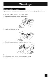
Note: • To re-install the stand, reverse the procedure from the TV. 4) Cover the hole with a bottom cover and tighten the screw. Warnings Disconnecting the stand If you disconnect the stand, attach the bottom cover and the screw (supplied) into the hole. 1) Place the TV face down on a soft cloth on a table. 2) Remove the four screws from the back of the TV. 3) Pull out the stand from 4) to 1). 7
Note: • To re-install the stand, reverse the procedure from the TV. 4) Cover the hole with a bottom cover and tighten the screw. Warnings Disconnecting the stand If you disconnect the stand, attach the bottom cover and the screw (supplied) into the hole. 1) Place the TV face down on a soft cloth on a table. 2) Remove the four screws from the back of the TV. 3) Pull out the stand from 4) to 1). 7
Instructions
Page 9
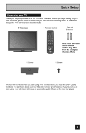
... SLEEP SUB CH V.STATUS SOUND 1 2 3 4 5 6 7 8 9 TUNE RETURN+/TV 0 V1 V2 V3 V4 MUTING CH+ V5 VO- VOL + CH- Before you begin setting up your new television, please check to make sure you have all of a JVC LCD Flat Television. ML/MTS DISPLAY C.C. ASPECT MENU BACK GUIDE OK RM-C1291... TV + AA Alkaline - + AA Alkaline - Quick Setup Unpacking your TV Thank you for your purchase of the following items. In addition to this...
... SLEEP SUB CH V.STATUS SOUND 1 2 3 4 5 6 7 8 9 TUNE RETURN+/TV 0 V1 V2 V3 V4 MUTING CH+ V5 VO- VOL + CH- Before you begin setting up your new television, please check to make sure you have all of a JVC LCD Flat Television. ML/MTS DISPLAY C.C. ASPECT MENU BACK GUIDE OK RM-C1291... TV + AA Alkaline - + AA Alkaline - Quick Setup Unpacking your TV Thank you for your purchase of the following items. In addition to this...
Instructions
Page 10
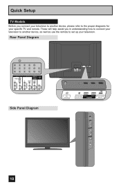
... Before you in understanding how to connect your television to another device, please refer to set up your specific TV and remote. Rear Panel Diagram AUDIO AUDIO AUDIO COMPONENT AUDIO COMPONENT AUDIO AUDIO AUDIO COMPONENT AUDIO COMPONENT INPUT 3 S-VIDEO Y VIDEO PB L PR R INPUT 4 INPUT 5 / INPUT 1 ...
... Before you in understanding how to connect your television to another device, please refer to set up your specific TV and remote. Rear Panel Diagram AUDIO AUDIO AUDIO COMPONENT AUDIO COMPONENT AUDIO AUDIO AUDIO COMPONENT AUDIO COMPONENT INPUT 3 S-VIDEO Y VIDEO PB L PR R INPUT 4 INPUT 5 / INPUT 1 ...
Instructions
Page 11
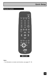
Remote Control Quick Setup POWER SLEEP SUB CH V.STATUS SOUND 1 2 3 4 5 6 7 8 9 TUNE RETURN+/TV 0 V1 V2 V3 V4 MUTING CH+ V5 VO- ASPECT MENU BACK GUIDE OK RM-C1291 TV RM-C1291 Notes: • For information on remote control buttons, see pages 57 - 64. 11 VOL + CH- L FAV. ML/MTS DISPLAY C.C.
Remote Control Quick Setup POWER SLEEP SUB CH V.STATUS SOUND 1 2 3 4 5 6 7 8 9 TUNE RETURN+/TV 0 V1 V2 V3 V4 MUTING CH+ V5 VO- ASPECT MENU BACK GUIDE OK RM-C1291 TV RM-C1291 Notes: • For information on remote control buttons, see pages 57 - 64. 11 VOL + CH- L FAV. ML/MTS DISPLAY C.C.
Instructions
Page 12
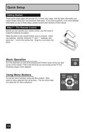
... the remote. If you are used only for more detailed information on the remote's back cover to remove. Basic Operation Turn the television on the TV, the interactive plug-in the remote first. Insert two batteries, carefully noting the "+" and "-" markings, and place the "-" end in menu appears. Snap the cover...
... the remote. If you are used only for more detailed information on the remote's back cover to remove. Basic Operation Turn the television on the TV, the interactive plug-in the remote first. Insert two batteries, carefully noting the "+" and "-" markings, and place the "-" end in menu appears. Snap the cover...
Instructions
Page 13
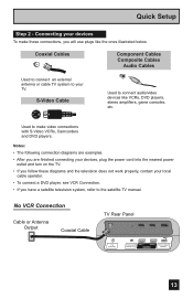
...diagrams are examples. • After you are finished connecting your devices, plug the power cord into the nearest power outlet and turn on the TV. • If you follow these connections, you have a satellite television system, refer to your devices To make video connections with S-Video VCRs,... Camcorders and DVD players. No VCR Connection Cable or Antenna Output Coaxial Cable TV Rear Panel 75 Ω (VHF/UHF) DIGITAL AUDIO INPUT 1 OPTICAL OUT INPUT 2 PHOTO VIEWER / SERVICE 13 Quick Setup Step 2 - Connecting your...
...diagrams are examples. • After you are finished connecting your devices, plug the power cord into the nearest power outlet and turn on the TV. • If you follow these connections, you have a satellite television system, refer to your devices To make video connections with S-Video VCRs,... Camcorders and DVD players. No VCR Connection Cable or Antenna Output Coaxial Cable TV Rear Panel 75 Ω (VHF/UHF) DIGITAL AUDIO INPUT 1 OPTICAL OUT INPUT 2 PHOTO VIEWER / SERVICE 13 Quick Setup Step 2 - Connecting your...
Instructions
Page 14
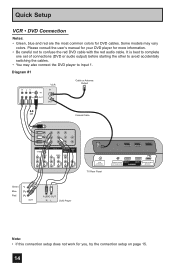
... AUDIO AUDIO AUDIO COMPONENT AUDIO COMPONENT INPUT 3 S-VIDEO Y VIDEO PB L PR R INPUT 4 Y VIDEO INPUT 5 / INPUT 1 AUDIO AUDIO OUT VIDEO PB L L L PR R R R 75 Ω (VHF/UHF) TV Rear Panel DIGITAL AUDIO INPUT 1 OPTICAL OUT INPUT 2 PHOTO VIEWER / SERVICE Green Blue Red Y PB PR OUT AUDIO OUT R L DVD Player Note: • If this...
... AUDIO AUDIO AUDIO COMPONENT AUDIO COMPONENT INPUT 3 S-VIDEO Y VIDEO PB L PR R INPUT 4 Y VIDEO INPUT 5 / INPUT 1 AUDIO AUDIO OUT VIDEO PB L L L PR R R R 75 Ω (VHF/UHF) TV Rear Panel DIGITAL AUDIO INPUT 1 OPTICAL OUT INPUT 2 PHOTO VIEWER / SERVICE Green Blue Red Y PB PR OUT AUDIO OUT R L DVD Player Note: • If this...
Instructions
Page 15
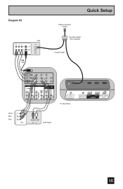
Diagram #2 R LV IN OUT VCR IN OUT OR Quick Setup Cable or Antenna Output IN Two-Way Splitter OUT OUT (Not supplied) Coaxial Cable AUDIO AUDIO AUDIO COMPONENT AUDIO COMPONENT INPUT 3 S-VIDEO Y VIDEO PB L PR R INPUT 4 INPUT 5 / INPUT 1 AUDIO AUDIO OUT Y VIDEO VIDEO PB L L L PR R R R 75 Ω (VHF/UHF) TV Rear Panel DIGITAL AUDIO INPUT 1 OPTICAL OUT INPUT 2 PHOTO VIEWER / SERVICE Green Blue Red Y PB PR OUT AUDIO OUT R L DVD Player 15
Diagram #2 R LV IN OUT VCR IN OUT OR Quick Setup Cable or Antenna Output IN Two-Way Splitter OUT OUT (Not supplied) Coaxial Cable AUDIO AUDIO AUDIO COMPONENT AUDIO COMPONENT INPUT 3 S-VIDEO Y VIDEO PB L PR R INPUT 4 INPUT 5 / INPUT 1 AUDIO AUDIO OUT Y VIDEO VIDEO PB L L L PR R R R 75 Ω (VHF/UHF) TV Rear Panel DIGITAL AUDIO INPUT 1 OPTICAL OUT INPUT 2 PHOTO VIEWER / SERVICE Green Blue Red Y PB PR OUT AUDIO OUT R L DVD Player 15
Instructions
Page 16
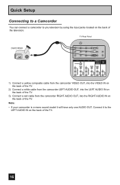
... L L L PR R R R AUDIO AUDIO AUDIO COMPONENT AUDIO COMPONENT 1) Connect a yellow composite cable from the camcorder VIDEO OUT, into the VIDEO IN on the back of the TV. 2) Connect a white cable from the camcorder LEFT AUDIO OUT, into the LEFT AUDIO IN on the back of the... TV. 3) Connect a red cable from the camcorder RIGHT AUDIO OUT, into the RIGHT AUDIO IN on the back of the TV. 16 Note: • If your camcorder is a mono sound model it to you televison by...
... L L L PR R R R AUDIO AUDIO AUDIO COMPONENT AUDIO COMPONENT 1) Connect a yellow composite cable from the camcorder VIDEO OUT, into the VIDEO IN on the back of the TV. 2) Connect a white cable from the camcorder LEFT AUDIO OUT, into the LEFT AUDIO IN on the back of the... TV. 3) Connect a red cable from the camcorder RIGHT AUDIO OUT, into the RIGHT AUDIO IN on the back of the TV. 16 Note: • If your camcorder is a mono sound model it to you televison by...
Instructions
Page 17
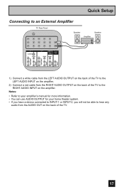
... have a device connected to INPUT-1 or INPUT-2, you will not be able to hear any audio from the AUDIO OUT on the back of the TV to the LEFT AUDIO INPUT on the amplifier. 2) Connect a red cable from the LEFT AUDIO OUTPUT on the back of the... TV to the RIGHT AUDIO INPUT on the back of the TV. 17 Quick Setup Connecting to an External Amplifier TV Rear Panel Speaker Amplifier Speaker INPUT 3 S-VIDEO Y VIDEO PB L PR R INPUT 4 Y VIDEO INPUT 5 / INPUT 1 AUDIO AUDIO...
... have a device connected to INPUT-1 or INPUT-2, you will not be able to hear any audio from the AUDIO OUT on the back of the TV to the LEFT AUDIO INPUT on the amplifier. 2) Connect a red cable from the LEFT AUDIO OUTPUT on the back of the... TV to the RIGHT AUDIO INPUT on the back of the TV. 17 Quick Setup Connecting to an External Amplifier TV Rear Panel Speaker Amplifier Speaker INPUT 3 S-VIDEO Y VIDEO PB L PR R INPUT 4 Y VIDEO INPUT 5 / INPUT 1 AUDIO AUDIO...
Instructions
Page 18
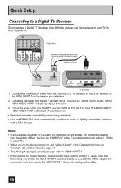
...their digital form. Analog/Digital" menu setting on the screen, the horizontal balance may be slightly shifted. Quick Setup Connecting to a Digital TV Receiver By connecting a Digital TV Receiver, high definition pictures can only be used with the HDMI INPUT-1. • When setting the "Video-1 Audio - Notes: &#...8226; If 480p signals (640x480 or 720x480) are displayed on the TV, please note that this connection must be made , tighten the screw to secure the cables. Access the "HDMI Size" in the External Input menu...
...their digital form. Analog/Digital" menu setting on the screen, the horizontal balance may be slightly shifted. Quick Setup Connecting to a Digital TV Receiver By connecting a Digital TV Receiver, high definition pictures can only be used with the HDMI INPUT-1. • When setting the "Video-1 Audio - Notes: &#...8226; If 480p signals (640x480 or 720x480) are displayed on the TV, please note that this connection must be made , tighten the screw to secure the cables. Access the "HDMI Size" in the External Input menu...
Instructions
Page 19
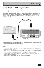
... an audio and/or video monitor, such as a digital television (DTV). See "Video-1 Audio", page 44. • Some decoders may be displayed on your TV in the External Input menu to 480p/60Hz), the screen may turn green and there may not respond depending on the equipment that is connected... form. HDMI Cable HDMI Compatible Device LR AUDIO OUT DIGITAL OUT 75 Ω (VHF/UHF) DIGITAL AUDIO INPUT 1 OPTICAL OUT INPUT 2 PHOTO VIEWER / SERVICE TV Rear Panel 1) Connect the HDMI Cable from the DIGITAL OUT on the back of your television. Quick Setup Connecting to the HDMI INPUT-1 on the...
... an audio and/or video monitor, such as a digital television (DTV). See "Video-1 Audio", page 44. • Some decoders may be displayed on your TV in the External Input menu to 480p/60Hz), the screen may turn green and there may not respond depending on the equipment that is connected... form. HDMI Cable HDMI Compatible Device LR AUDIO OUT DIGITAL OUT 75 Ω (VHF/UHF) DIGITAL AUDIO INPUT 1 OPTICAL OUT INPUT 2 PHOTO VIEWER / SERVICE TV Rear Panel 1) Connect the HDMI Cable from the DIGITAL OUT on the back of your television. Quick Setup Connecting to the HDMI INPUT-1 on the...
Instructions
Page 20
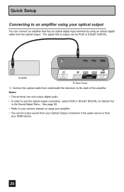
Amplifier 75 Ω (VHF/UHF) DIGITAL AUDIO INPUT 1 OPTICAL OUT INPUT 2 PHOTO VIEWER / SERVICE TV Rear Panel 1) Connect the optical cable from your HDMI device. 20 The signal that has an optical digital input terminal by using an optical digital ...
Amplifier 75 Ω (VHF/UHF) DIGITAL AUDIO INPUT 1 OPTICAL OUT INPUT 2 PHOTO VIEWER / SERVICE TV Rear Panel 1) Connect the optical cable from your HDMI device. 20 The signal that has an optical digital input terminal by using an optical digital ...
Instructions
Page 21
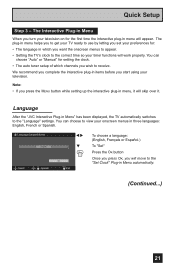
... choose to view your onscreen menus in which channels you start using your timer functions will skip over it will work properly. Language After the "JVC Interactive Plug-in items before you wish to the correct time so your television. You can choose "Auto" or "Manual" for setting the clock...: English, French or Spanish. Quick Setup Step 3 - The plug-in menu helps you to get your TV ready to use by letting you want the onscreen menus to appear. • Setting the TV's clock to receive. Note: • If you will appear. Language/Langue/Idioma English Select OK Operate &#...
... choose to view your onscreen menus in which channels you start using your timer functions will skip over it will work properly. Language After the "JVC Interactive Plug-in items before you wish to the correct time so your television. You can choose "Auto" or "Manual" for setting the clock...: English, French or Spanish. Quick Setup Step 3 - The plug-in menu helps you to get your TV ready to use by letting you want the onscreen menus to appear. • Setting the TV's clock to receive. Note: • If you will appear. Language/Langue/Idioma English Select OK Operate &#...
Instructions
Page 22
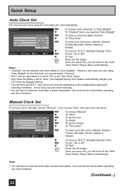
In this case, set your TV's clock for the first time, you cannot select "Channel". • D.S.T. Manual Clock Set To set correctly depending on the broadcasting signal and receiving conditions. Note: &#...
In this case, set your TV's clock for the first time, you cannot select "Channel". • D.S.T. Manual Clock Set To set correctly depending on the broadcasting signal and receiving conditions. Note: &#...
Instructions
Page 23
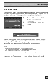
... without doing the Auto Tuner Setup. is now complete." Setup is displayed. Quick Setup Auto Tuner Setup In auto tuner setup, the TV automatically scans through all available channels, memorizing the active ones and skipping over blank ones or channels with weak signals. buttons) you !... quick setup is normal. 23 This is now complete. Cable Users: After your television viewing experience. This means when you scan (using the JVC onscreen menu system to cancel the Auto Tuner Setup, press the MENU button. • Noise muting will receive only clear, active channels. Notes...
... without doing the Auto Tuner Setup. is now complete." Setup is displayed. Quick Setup Auto Tuner Setup In auto tuner setup, the TV automatically scans through all available channels, memorizing the active ones and skipping over blank ones or channels with weak signals. buttons) you !... quick setup is normal. 23 This is now complete. Cable Users: After your television viewing experience. This means when you scan (using the JVC onscreen menu system to cancel the Auto Tuner Setup, press the MENU button. • Noise muting will receive only clear, active channels. Notes...


