
Instructions
Page 1
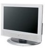
Staple your television (located at the rear of this user's guide in a convenient place for future use. Keep the carton and original packaging for future reference. Model Number: Serial Number: LCT1899-001A-A 0605TNH-II-IM LCD Flat Television Users Guide For Models: LT-32X506 LT-26X506 Illustration of LT-32X506 and RM-C1271G Important Note: In the spaces below, enter the model and serial number of your sales receipt or invoice to the inside cover of the television cabinet). Keep this guide.
Staple your television (located at the rear of this user's guide in a convenient place for future use. Keep the carton and original packaging for future reference. Model Number: Serial Number: LCT1899-001A-A 0605TNH-II-IM LCD Flat Television Users Guide For Models: LT-32X506 LT-26X506 Illustration of LT-32X506 and RM-C1271G Important Note: In the spaces below, enter the model and serial number of your sales receipt or invoice to the inside cover of the television cabinet). Keep this guide.

Instructions
Page 3
• As an "ENERGY STAR®" partner, JVC has determined that produce heat. 9) Do not defeat the safety purpose of the obsolete outlet. 10) Protect the power cord from being walked on or .... When a cart is used, use caution when moving the cart/apparatus combination to avoid injury from the apparatus. 11) Only use this product or product model meets the "ENERGY STAR®" guidelines for replacement of the polarized or grounding-type plug.
• As an "ENERGY STAR®" partner, JVC has determined that produce heat. 9) Do not defeat the safety purpose of the obsolete outlet. 10) Protect the power cord from being walked on or .... When a cart is used, use caution when moving the cart/apparatus combination to avoid injury from the apparatus. 11) Only use this product or product model meets the "ENERGY STAR®" guidelines for replacement of the polarized or grounding-type plug.

Instructions
Page 7
Table of Contents Important Safety Precautions . . 2 Warnings 5 Quick Setup 8 Unpacking your TV 8 TV Model 9 TV Remote Control 10 Getting Started 11 Using the Stand 11 The Remote Control 12 Connecting Your Devices 13 Auto Tuner Setup 18 Remote Programming . . . . . 19 ... 45 Input 45 Display 46 Sleep Timer 46 Sound 47 Video Status 47 TheaterPro D6500K 47 OK 47 Back 47 Aspect 48 Aspect Ratios 48 TV/CATV Slide Switch 49 VCR/DVD Slide Switch 49 VCR Buttons 49 DVD Buttons 49 Appendices 50 No Program 50 Troubleshooting 51 Warranty 52 Authorized...
Table of Contents Important Safety Precautions . . 2 Warnings 5 Quick Setup 8 Unpacking your TV 8 TV Model 9 TV Remote Control 10 Getting Started 11 Using the Stand 11 The Remote Control 12 Connecting Your Devices 13 Auto Tuner Setup 18 Remote Programming . . . . . 19 ... 45 Input 45 Display 46 Sleep Timer 46 Sound 47 Video Status 47 TheaterPro D6500K 47 OK 47 Back 47 Aspect 48 Aspect Ratios 48 TV/CATV Slide Switch 49 VCR/DVD Slide Switch 49 VCR Buttons 49 DVD Buttons 49 Appendices 50 No Program 50 Troubleshooting 51 Warranty 52 Authorized...

Instructions
Page 9
Rear Panel Diagram AUDIO OUT INPUT 3 INPUT 2 L - AUDIO - POWER OPERATE 9 Quick Setup TV Model NOTE: Before you in understanding how to connect your television to another device, please refer to set up your specific TV and remote. R L I VIDEO AUDIO I R VIDEO SVIDEO L I AUDIO I R VIDEO SVIDEO L I AUDIO I R INPUT 1 Y Pb Pr 75Ω (VHF/UHF) In the rear cover Side Panel Diagram INPUT MENU + CHANNEL - + VOLUME - These will help assist you connect your television to another device, as well as use the remote to the proper diagrams for your television.
Rear Panel Diagram AUDIO OUT INPUT 3 INPUT 2 L - AUDIO - POWER OPERATE 9 Quick Setup TV Model NOTE: Before you in understanding how to connect your television to another device, please refer to set up your specific TV and remote. R L I VIDEO AUDIO I R VIDEO SVIDEO L I AUDIO I R VIDEO SVIDEO L I AUDIO I R INPUT 1 Y Pb Pr 75Ω (VHF/UHF) In the rear cover Side Panel Diagram INPUT MENU + CHANNEL - + VOLUME - These will help assist you connect your television to another device, as well as use the remote to the proper diagrams for your television.

Instructions
Page 15
... L I AUDIO I R INPUT 2 VIDEO SVIDEO L I AUDIO I R VIDEO SVIDEO L I AUDIO I R INPUT 1 Y Pb Pr IN 75Ω (VHOF/UUHTF) VCR IN OUT V LR OR TV Rear Panel AUDIO OUT L R Y PB PR OUT DVD Player (OPTIONAL) Green Blue Red 15 It is best to complete one set of connections (DVD or ...other to avoid accidentally switching the cables. • You may vary colors. Please consult the user's manual for your DVD player for DVD cables. Some models may also connect the DVD player to Input 1. Quick Setup Connections Notes: • Green, blue and red are the most common colors for more ...
... L I AUDIO I R INPUT 2 VIDEO SVIDEO L I AUDIO I R VIDEO SVIDEO L I AUDIO I R INPUT 1 Y Pb Pr IN 75Ω (VHOF/UUHTF) VCR IN OUT V LR OR TV Rear Panel AUDIO OUT L R Y PB PR OUT DVD Player (OPTIONAL) Green Blue Red 15 It is best to complete one set of connections (DVD or ...other to avoid accidentally switching the cables. • You may vary colors. Please consult the user's manual for your DVD player for DVD cables. Some models may also connect the DVD player to Input 1. Quick Setup Connections Notes: • Green, blue and red are the most common colors for more ...

Instructions
Page 16
Note: • If your camcorder is a mono sound model it to the LEFT AUDIO IN on the back of the TV. UME - CAMCORDER AUDIO OUT INPUT 3 INPUT 2 TV Rear Panel L - Connect it will have only one AUDIO OUT. Headphone Connection You can connect a camcorder to you televison by ...using the headphone jack located on the side of the television. 1) Plug a headphone jack into the RIGHT AUDIO IN on the back of the TV. R L I VIDEO AUDIO I R OR VIDEO SVIDEO L I AUDIO I R VIDEO SVIDEO L I AUDIO I R INPUT 1 Y Pb Pr 1) Connect a yellow composite cable from the camcorder VIDEO ...
Note: • If your camcorder is a mono sound model it to the LEFT AUDIO IN on the back of the TV. UME - CAMCORDER AUDIO OUT INPUT 3 INPUT 2 TV Rear Panel L - Connect it will have only one AUDIO OUT. Headphone Connection You can connect a camcorder to you televison by ...using the headphone jack located on the side of the television. 1) Plug a headphone jack into the RIGHT AUDIO IN on the back of the TV. R L I VIDEO AUDIO I R OR VIDEO SVIDEO L I AUDIO I R VIDEO SVIDEO L I AUDIO I R INPUT 1 Y Pb Pr 1) Connect a yellow composite cable from the camcorder VIDEO ...

Instructions
Page 54
Note: • Reception of channel A-5 ("95" of the TV set's on-screen cable channel numbers) is not recommended for your TV set. 54 Specifications Model Type Reception Format LT-26X506 LT-32X506 LCD Flat Television NTSC, BTSC System (Multi-Channel Sound) Reception Range Power Source Power Consumption Screen Size... Super, Hyper and Ultra bands (180 channel frequency synthesizer system) AC 120V, 60 Hz 124W 26 inch / 65 cm measured diagonally, 16:9 ratio 186W 32 inch / 80 cm measured diagonally, 16:9 ratio 6.6 cm round X 2 Full Range - 5W + 5W 75 ohms (VHF/UHF) (F-type connector) Video...
Note: • Reception of channel A-5 ("95" of the TV set's on-screen cable channel numbers) is not recommended for your TV set. 54 Specifications Model Type Reception Format LT-26X506 LT-32X506 LCD Flat Television NTSC, BTSC System (Multi-Channel Sound) Reception Range Power Source Power Consumption Screen Size... Super, Hyper and Ultra bands (180 channel frequency synthesizer system) AC 120V, 60 Hz 124W 26 inch / 65 cm measured diagonally, 16:9 ratio 186W 32 inch / 80 cm measured diagonally, 16:9 ratio 6.6 cm round X 2 Full Range - 5W + 5W 75 ohms (VHF/UHF) (F-type connector) Video...


