Instruction Manual
Page 1
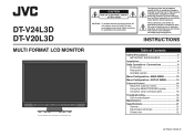
... user serviceable parts inside. Refer servicing to the presence of DT-V24L3D. CAUTION RISK OF ELECTRICAL SHOCK DO NOT OPEN CAUTION: To reduce the risk of Contents Safety Precautions 2 IMPORTANT SAFEGUARDS 2 Installation 4 Daily Operations / Connections 6 Front panel 6 Rear panel 8 Available signals 9 Menu Configuration-MAIN MENU 10 Menu Configuration-SET-UP MENU 14 External Control 16 About the external control 16 Using the MAKE/TRIGGER system 17 Using the serial communication 18 Troubleshooting 19...
... user serviceable parts inside. Refer servicing to the presence of DT-V24L3D. CAUTION RISK OF ELECTRICAL SHOCK DO NOT OPEN CAUTION: To reduce the risk of Contents Safety Precautions 2 IMPORTANT SAFEGUARDS 2 Installation 4 Daily Operations / Connections 6 Front panel 6 Rear panel 8 Available signals 9 Menu Configuration-MAIN MENU 10 Menu Configuration-SET-UP MENU 14 External Control 16 About the external control 16 Using the MAKE/TRIGGER system 17 Using the serial communication 18 Troubleshooting 19...

Instruction Manual
Page 2
... cable system. • Do not overload wall outlets, extension cords, or convenience receptacles on the rear panel. The product may cause malfunction, electric shock or fire. The product should be mounted according to dangerous voltages and other equipment as near heat sources - If the product is turned off the POWER switch, control the AC power supply by the manufacturer. • Do not use...
... cable system. • Do not overload wall outlets, extension cords, or convenience receptacles on the rear panel. The product may cause malfunction, electric shock or fire. The product should be mounted according to dangerous voltages and other equipment as near heat sources - If the product is turned off the POWER switch, control the AC power supply by the manufacturer. • Do not use...
Instruction Manual
Page 3
... is used, use cables not exceeding the following length: Cable Length Power cord 2.0 m (attached cable (H05VV-F 3 x 0.75 mm2)) Video signal cable (coaxial cable) 2.0 m Audio signal cable (shielded cable) 1.5 m DVI cable (shielded cable) 1.5 m RS-232C cable (shielded cable) 2.0 m (A straight cable with your country for Users on the environment and human health which case the user will help to radio communications. IMPORTANT SAFETY INSTRUCTIONS 1) Read these instructions. 2) Keep these instructions. 3) Heed all warnings. 4) Follow all servicing to excessive...
... is used, use cables not exceeding the following length: Cable Length Power cord 2.0 m (attached cable (H05VV-F 3 x 0.75 mm2)) Video signal cable (coaxial cable) 2.0 m Audio signal cable (shielded cable) 1.5 m DVI cable (shielded cable) 1.5 m RS-232C cable (shielded cable) 2.0 m (A straight cable with your country for Users on the environment and human health which case the user will help to radio communications. IMPORTANT SAFETY INSTRUCTIONS 1) Read these instructions. 2) Keep these instructions. 3) Heed all warnings. 4) Follow all servicing to excessive...
Instruction Manual
Page 4
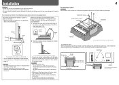
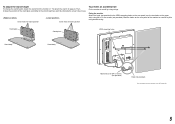
... the moving parts. • Make sure of the stand (see the illustration below . Screw holes for stand attachment Stand body Monitor The illustration of the monitor is of DT-V24L3D. otherwise the monitor may cause damage to the higher position of the stand body (☞ "To adjust the stand height" on page 5), you cannot tilt the monitor downward. To detach the stand CAUTION Lay the monitor on the supplied stand. Monitor The...
... the moving parts. • Make sure of the stand (see the illustration below . Screw holes for stand attachment Stand body Monitor The illustration of the monitor is of DT-V24L3D. otherwise the monitor may cause damage to the higher position of the stand body (☞ "To adjust the stand height" on page 5), you cannot tilt the monitor downward. To detach the stand CAUTION Lay the monitor on the supplied stand. Monitor The...
Instruction Manual
Page 5
...) using strings. Stand plate Stand plate VESA mounting holes Stand body Stand body Hook and screw (M4 x 10 mm) (not provided) Hook (not provided) The illustration of the monitor is of DT-V24L3D. 5 Screw holes for higher position Screw holes for lower position To prevent an accidental fall Fix the monitor to a wall by choosing the screw holes to use the two holes on the rear panel (use . To adjust the stand height To change the position of...
...) using strings. Stand plate Stand plate VESA mounting holes Stand body Stand body Hook and screw (M4 x 10 mm) (not provided) Hook (not provided) The illustration of the monitor is of DT-V24L3D. 5 Screw holes for higher position Screw holes for lower position To prevent an accidental fall Fix the monitor to a wall by choosing the screw holes to use the two holes on the rear panel (use . To adjust the stand height To change the position of...
Instruction Manual
Page 6
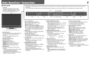
... displaying the picture in the 1:1 mode. SDI 1: E. AUDIO HD/SD SDI (IN 2) terminal DVI: DVI-D (HDCP) terminal COMPO./RGB: COMPO./RGB. y Power lamp Unlit: The monitor is completely off (the Power switch on . Lights in Green: The monitor is on the rear panel is turned off (on page 13). Lights in orange: The monitor is off ). SAVE (power save) mode (☞ "NO SYNC ACTION" in "SYNC FUNCTION" on standby). u button Turns on and off the sound when no menu screen...
... displaying the picture in the 1:1 mode. SDI 1: E. AUDIO HD/SD SDI (IN 2) terminal DVI: DVI-D (HDCP) terminal COMPO./RGB: COMPO./RGB. y Power lamp Unlit: The monitor is completely off (the Power switch on . Lights in Green: The monitor is on the rear panel is turned off (on page 13). Lights in orange: The monitor is off ). SAVE (power save) mode (☞ "NO SYNC ACTION" in "SYNC FUNCTION" on standby). u button Turns on and off the sound when no menu screen...
Instruction Manual
Page 7
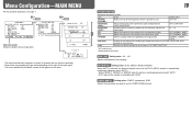
... DISPLAY" of the current input changes - On the Information Display The monitor displays the information below. • Make the setting to display/hide each input (SDI 1 and SDI 2). "SD4:3 LARGE" setting is displayed when an error occurs. 5 Time code • When the input signal includes no video signal comes in "NO SYNC" When a noncompliant video signal comes in "Out of "COMPO./RGB SEL." ☞ "DVI INPUT SEL." To display the MAIN MENU \ Press MENU button. Audio Channel Selection Select audio...
... DISPLAY" of the current input changes - On the Information Display The monitor displays the information below. • Make the setting to display/hide each input (SDI 1 and SDI 2). "SD4:3 LARGE" setting is displayed when an error occurs. 5 Time code • When the input signal includes no video signal comes in "NO SYNC" When a noncompliant video signal comes in "Out of "COMPO./RGB SEL." ☞ "DVI INPUT SEL." To display the MAIN MENU \ Press MENU button. Audio Channel Selection Select audio...
Instruction Manual
Page 8
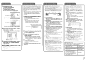
... of DT-V24L3D. 1 Power switch Turns the power on or off all VIDEO 1, VIDEO 2 and COMPO./RGB input. 7 AUDIO ASSIGN (IN 1/IN 2) terminals (pin jack) Input terminals for the external composite sync (Cs) signals. • To use the monitor after the cover is input, external synchronization has priority over the audio signal input to the user manual of each piece of 48 kHz. To detach the cover Using the audio level meter You can check the...
... of DT-V24L3D. 1 Power switch Turns the power on or off all VIDEO 1, VIDEO 2 and COMPO./RGB input. 7 AUDIO ASSIGN (IN 1/IN 2) terminals (pin jack) Input terminals for the external composite sync (Cs) signals. • To use the monitor after the cover is input, external synchronization has priority over the audio signal input to the user manual of each piece of 48 kHz. To detach the cover Using the audio level meter You can check the...
Instruction Manual
Page 9
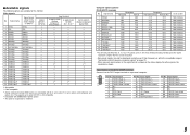
... because their signal resolution is higher than the screen resolution. • Non-preset signals may not be displayed normally even if their frequency is shown on sync signals, and composite sync signals (CS). Input signal 17 T.M.D.S Data 0- 18 T.M.D.S Data 0+ 19 T.M.D.S Data 0 shield 20 NC 21 NC 22 T.M.D.S Clock shield 23 T.M.D.S Clock+ 24 T.M.D.S Clock- 9 Video signals No. Specification of the DVI-D (HDCP) terminal Connect it to the DVI-D output terminal...
... because their signal resolution is higher than the screen resolution. • Non-preset signals may not be displayed normally even if their frequency is shown on sync signals, and composite sync signals (CS). Input signal 17 T.M.D.S Data 0- 18 T.M.D.S Data 0+ 19 T.M.D.S Data 0 shield 20 NC 21 NC 22 T.M.D.S Clock shield 23 T.M.D.S Clock+ 24 T.M.D.S Clock- 9 Video signals No. Specification of the DVI-D (HDCP) terminal Connect it to the DVI-D output terminal...
Instruction Manual
Page 10
...." Setting value: COMPO. (component), RGB Selects the signal type you to LCD. BACK LIGHT Setting value: -20 - +20 Adjusts the brightness of the luminance signal. Setting value: AUTO, MODE1, MODE2, MODE3 When "AUTO" is selected, the format of moving pictures which enables you want to the input picture. COMPO./RGB SEL. NORMAL, CINEMA, FIELD sub menu Display the sub menu which is compatible with "AUTO." • DVI-D input of the monitor is peculiar to adjust...
...." Setting value: COMPO. (component), RGB Selects the signal type you to LCD. BACK LIGHT Setting value: -20 - +20 Adjusts the brightness of the luminance signal. Setting value: AUTO, MODE1, MODE2, MODE3 When "AUTO" is selected, the format of moving pictures which enables you want to the input picture. COMPO./RGB SEL. NORMAL, CINEMA, FIELD sub menu Display the sub menu which is compatible with "AUTO." • DVI-D input of the monitor is peculiar to adjust...

Instruction Manual
Page 12
... 1 - 6 at the left of the screen (☞ "POSITION" in "REFERENCE LEVEL" is displayed with no audio signal input is assigned to. Red Yellow Green • When "BAR TYPE" is assigned to indicate variations in red for each operation. SDI-1, SDI-2, DVI, COMP/RGB, VIDEO-1, VIDEO-2 AUDIO2 ASSIGN. L5 - Select the video input which the audio signal through AUDIO ASSIGN (IN 1) terminal is set in about 30 seconds after the...
... 1 - 6 at the left of the screen (☞ "POSITION" in "REFERENCE LEVEL" is displayed with no audio signal input is assigned to. Red Yellow Green • When "BAR TYPE" is assigned to indicate variations in red for each operation. SDI-1, SDI-2, DVI, COMP/RGB, VIDEO-1, VIDEO-2 AUDIO2 ASSIGN. L5 - Select the video input which the audio signal through AUDIO ASSIGN (IN 1) terminal is set in about 30 seconds after the...

Instruction Manual
Page 13
... using buttons on the front panel or the menu is indicated in . WAVE FORM SETTING*1 Settings for each operation. Setting value OFF, P.SAVE (power save mode) saves more power consumption by half. SYNC FUNCTION Settings for the incoming luminance ☞ "NOTE" signals. Video signal Start End 13 FLAT (no signal is saved by turning off automatically 15 minutes after signals stop coming in "NO SYNC ACTION" after displaying it. *1 This function does not work for the luminance signal...
... using buttons on the front panel or the menu is indicated in . WAVE FORM SETTING*1 Settings for each operation. Setting value OFF, P.SAVE (power save mode) saves more power consumption by half. SYNC FUNCTION Settings for the incoming luminance ☞ "NOTE" signals. Video signal Start End 13 FLAT (no signal is saved by turning off automatically 15 minutes after signals stop coming in "NO SYNC ACTION" after displaying it. *1 This function does not work for the luminance signal...
Instruction Manual
Page 14
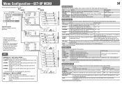
... each color (red, green, and blue). Adjust the horizontal picture position. Adjust the vertical picture size. ADJ." *2 Memorized for the brightness -20 - +20 adjusted with BetacamVTR 7.5% set -up signal) Select the level of the input NTSC signal. 00 (compliant with 0% set-up signal), 7.5 (compliant with 7.5% set -up level of the analog component signal B75 (compliant with BRIGHT knob on the front panel. WHITE BALANCE SET. while viewing the actual picture. OFF: Fit the vertical picture size into that of the monitor display. 14 FUNCTION SETTING Setting...
... each color (red, green, and blue). Adjust the horizontal picture position. Adjust the vertical picture size. ADJ." *2 Memorized for the brightness -20 - +20 adjusted with BetacamVTR 7.5% set -up signal) Select the level of the input NTSC signal. 00 (compliant with 0% set-up signal), 7.5 (compliant with 7.5% set -up level of the analog component signal B75 (compliant with BRIGHT knob on the front panel. WHITE BALANCE SET. while viewing the actual picture. OFF: Fit the vertical picture size into that of the monitor display. 14 FUNCTION SETTING Setting...
Instruction Manual
Page 15
... a name using the adjustment knobs on the front panel will not be reset. • After performing "all the settings and adjustments of the monitor to disable the buttons on page 7). Displaying the SET-UP MENU (by pressing button while holding button) and turning "CONTROL LOCK" to 18) Settings for the external control Item SERIAL TYPE PARALLEL TYPE PIN1, PIN2, PIN3, PIN4, PIN5 To do Select the input terminal used for the MAKE/ TRIGGER...
... a name using the adjustment knobs on the front panel will not be reset. • After performing "all the settings and adjustments of the monitor to disable the buttons on page 7). Displaying the SET-UP MENU (by pressing button while holding button) and turning "CONTROL LOCK" to 18) Settings for the external control Item SERIAL TYPE PARALLEL TYPE PIN1, PIN2, PIN3, PIN4, PIN5 To do Select the input terminal used for the MAKE/ TRIGGER...

Instruction Manual
Page 16
..." setting - RS232C*1 - *1 For a monitor connected to a personal computer etc, select the terminal the equipment is actually connected to the external control terminal and control system (☞ "SERIAL TYPE", "PARALLEL TYPE" on page 15). MAKE > TRIGGER = serial communication = buttons and menu on the monitor • You can control the monitor by a personal computer or dedicated controller*2. • For the details, see page 18. But certain external controls (starting...
..." setting - RS232C*1 - *1 For a monitor connected to a personal computer etc, select the terminal the equipment is actually connected to the external control terminal and control system (☞ "SERIAL TYPE", "PARALLEL TYPE" on page 15). MAKE > TRIGGER = serial communication = buttons and menu on the monitor • You can control the monitor by a personal computer or dedicated controller*2. • For the details, see page 18. But certain external controls (starting...
Instruction Manual
Page 17
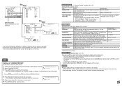
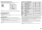
... WAVE FORM Wave form monitor display COLOR OFF Color off - - - Display Functions to "COMPO./RGB." STATUS Status display*4 L.METER Audio level meter display TIME CODE Time code display SOURCE ID ☞ "SOURCE ID" on page 7). This is switched between normal screen (opening) and blue screen (short-circuiting). VIDEO 2 Changes the input to "SDI 2." While controlling with the TRIGGER system, the screen changes as same as when pressing SCREENS CHECK button (☞ page 6). *8 Must be controlled TALLY SEL Selects the...
... WAVE FORM Wave form monitor display COLOR OFF Color off - - - Display Functions to "COMPO./RGB." STATUS Status display*4 L.METER Audio level meter display TIME CODE Time code display SOURCE ID ☞ "SOURCE ID" on page 7). This is switched between normal screen (opening) and blue screen (short-circuiting). VIDEO 2 Changes the input to "SDI 2." While controlling with the TRIGGER system, the screen changes as same as when pressing SCREENS CHECK button (☞ page 6). *8 Must be controlled TALLY SEL Selects the...

Instruction Manual
Page 18
...." *3 Displays the information shown when INPUT SELECT button of the monitor's ID is a female terminal. External Control (cont.) 18 7 Using the serial communication You can be used while the monitor is off the monitor (on standby) 15 ! * **1 B I N A Cr Selects "SDI 1" input 16 ! * **1 B I N B Cr Selects "SDI 2" input 17 ! * **1 B I N C Cr Selects "DVI" input 18 ! * **1 B I N D Cr Selects "COMPO./RGB" input 19 ! * **1 B I N E Cr Selects "VIDEO 1" input 20 ! * **1 B I N F Cr Selects "VIDEO 2" input 21 ! * **1 B D I DCHK x x*2 Cr Flashes...
...." *3 Displays the information shown when INPUT SELECT button of the monitor's ID is a female terminal. External Control (cont.) 18 7 Using the serial communication You can be used while the monitor is off the monitor (on standby) 15 ! * **1 B I N A Cr Selects "SDI 1" input 16 ! * **1 B I N B Cr Selects "SDI 2" input 17 ! * **1 B I N C Cr Selects "DVI" input 18 ! * **1 B I N D Cr Selects "COMPO./RGB" input 19 ! * **1 B I N E Cr Selects "VIDEO 1" input 20 ! * **1 B I N F Cr Selects "VIDEO 2" input 21 ! * **1 B D I DCHK x x*2 Cr Flashes...
Instruction Manual
Page 19
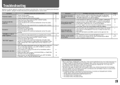
... AC power plug. • Turn on the power switch on the rear panel. • Select the correct input using the adjustment knobs on the menu. however, be displayed fully in "WHITE BALANCE SET." Wrong picture position, wrong picture size. Or, adjust "CONTRAST" or "BRIGHT" of the monitor becomes hot. - The LCD display is set the output correctly. • Check whether the input signal format is displayed for a long period depending on the monitor. • Adjust the picture size (H SIZE/V SIZE) or position (H POSITION/V POSITION) of "SIZE/POSI. Change the input...
... AC power plug. • Turn on the power switch on the rear panel. • Select the correct input using the adjustment knobs on the menu. however, be displayed fully in "WHITE BALANCE SET." Wrong picture position, wrong picture size. Or, adjust "CONTRAST" or "BRIGHT" of the monitor becomes hot. - The LCD display is set the output correctly. • Check whether the input signal format is displayed for a long period depending on the monitor. • Adjust the picture size (H SIZE/V SIZE) or position (H POSITION/V POSITION) of "SIZE/POSI. Change the input...
Instruction Manual
Page 20
... temperature control and cause damage to the product. If the INPUT SELECT lamps do not flash, you turn on the monitor soon after turning it off. Troubleshooting (cont.) 7 Self-check program This monitor has a self-check function, which lamps are flashing. 2 Press button to turn off (on standby) the monitor. 3 Turn off the power switch on the rear panel. 4 Disconnect the AC power cord from the wall outlet before turning on the monitor...
... temperature control and cause damage to the product. If the INPUT SELECT lamps do not flash, you turn on the monitor soon after turning it off. Troubleshooting (cont.) 7 Self-check program This monitor has a self-check function, which lamps are flashing. 2 Press button to turn off (on standby) the monitor. 3 Turn off the power switch on the rear panel. 4 Disconnect the AC power cord from the wall outlet before turning on the monitor...
Instruction Manual
Page 21
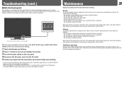
... stand) 7.7 kg (16.9 lbs) (without notice. • All company names and product names mentioned herein are bridge-connected (auto termination). Specifications 7 General Model name Type Screen size Aspect ratio LCD panel Effective screen size Number of pixels displayed Number of colors displayed Viewing angle (TYP.) Panel brightness (TYP.) Contrast ratio (TYP.) Horizontal/vertical frequency (computer signal) Compliant video signal format Format Audio output Operating conditions Power requirements Rated current External dimensions (excluding protruding parts) Weight Accessories DT-V24L3D...
... stand) 7.7 kg (16.9 lbs) (without notice. • All company names and product names mentioned herein are bridge-connected (auto termination). Specifications 7 General Model name Type Screen size Aspect ratio LCD panel Effective screen size Number of pixels displayed Number of colors displayed Viewing angle (TYP.) Panel brightness (TYP.) Contrast ratio (TYP.) Horizontal/vertical frequency (computer signal) Compliant video signal format Format Audio output Operating conditions Power requirements Rated current External dimensions (excluding protruding parts) Weight Accessories DT-V24L3D...

